ASM AllPro APB2525H User manual

309882GOperating Instructions
Manufactured by
APB2525H Pressure Washer
Important Safety Instructions
Read all warnings and instructions in this
manual. Save These instructions.
Model 246797, Series A & Series B
2300 psi (159 bar, 15.8 MPa) Maximum Operating Pressure
2500 psi (172 bar, 17.2 MPa) Maximum Working Pressure

2309882
Table of Contents
Symbols 2. . . . . . . . . . . . . . . . . . . . . . . . . . . . . . . . . . . . . .
Warnings 3. . . . . . . . . . . . . . . . . . . . . . . . . . . . . . . . . . . . . .
Component Identification 4. . . . . . . . . . . . . . . . . . . . . . . .
Pressure Relief Procedure 6. . . . . . . . . . . . . . . . . . . . . . .
Installing and Changing Spray Tips 11. . . . . . . . . . . . . .
Pump Service 17. . . . . . . . . . . . . . . . . . . . . . . . . . . . . . . . .
Parts Drawing 20. . . . . . . . . . . . . . . . . . . . . . . . . . . . . . . . .
Parts List 21. . . . . . . . . . . . . . . . . . . . . . . . . . . . . . . . . . . . .
ASM Phone Number 24. . . . . . . . . . . . . . . . . . . . . . . . . . .
Warning Symbol
WARNING
This symbol alerts you to the possibility of serious inju-
ry or death if you do not follow instructions.
Caution Symbol
CAUTION
This symbol alerts you to the possibility of damage to
or destruction of equipment if you do not follow instruc-
tions.

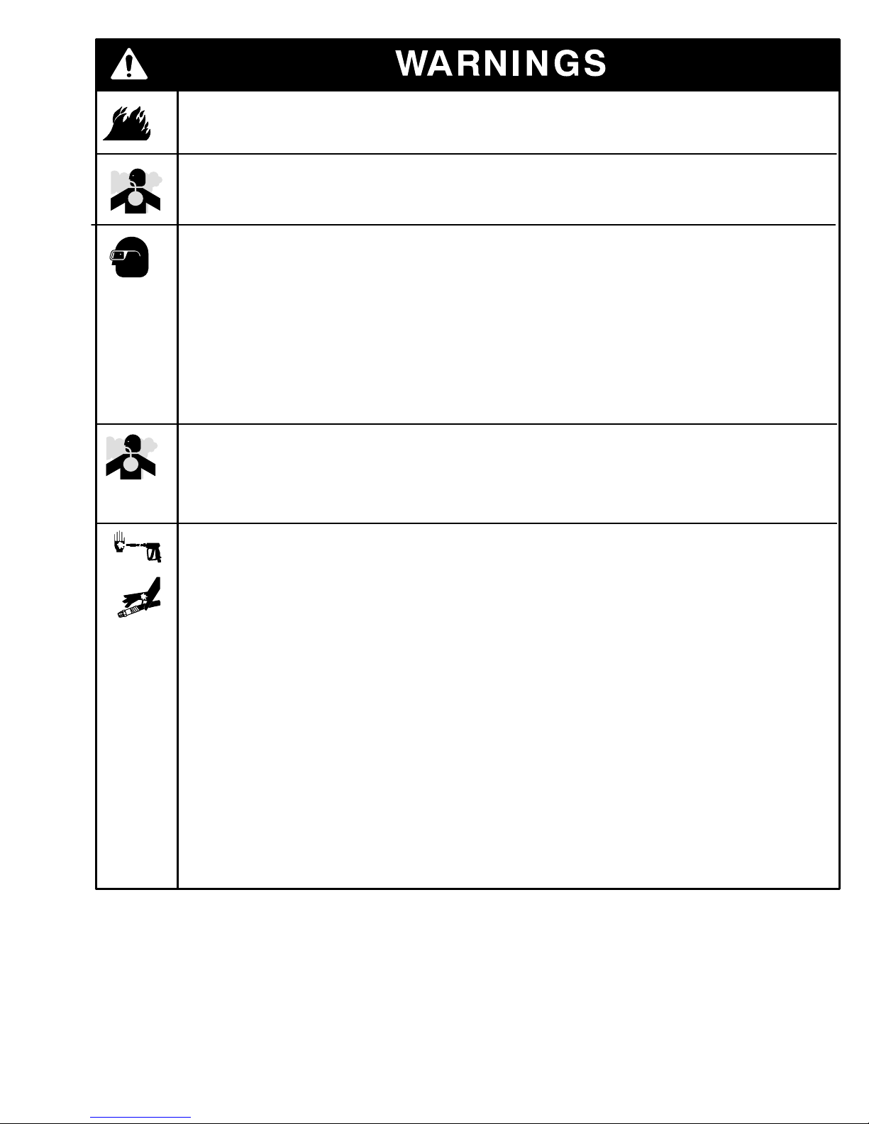
Equipment Misuse Hazard:
Misuse of pressure washer or accessories can cause the equipment to rupture or malfunction and
result in serious injury.
Do not alter or modify any part or factory–setting
Check equipment daily. Repair or replace worn or damaged parts immediately.
Do not exceed maximum working pressure (MWPR) of the lowest–rated system component
Use fluids and solvents that are compatible with the equipment wetted parts. See Specification
page for this information.
Wear hearing protection when operating this equipment.
Do not “blow back” fluid; this is not an air spray system
Follow Pressure Relief, page 6 before cleaning, checking or servicing equipment.
SKIN INJECTION HAZARD:
Spray from gun, leaks or ruptured components can inject fluid into your body and cause serious
injury. Fluid splashed in eyes or on skin can also cause serious injury.
Fluid injected into skin might look like just a cut, but it is a serious injury. Get immediate surgi-
cal treatment.
Do not point gun at anyone or any part of the body.
Do not stop or deflect leaks with hand, body, glove, or rag.
Do not put your hand or fingers over the spray tip.
TIghten fluid connections before you start this equipment.
Engage the gun safety whenever you stop spraying.
Follow Pressure Relief Procedure, page 6 if the spray tip clogs and before you clean, check
or service this equipment.
Repair or replace worn or damaged parts immediately.
Check hoses, tubes, and couplings daily. Do not repair high–pressure couplings. Replace entire
hose. Fluid hoses must have spring guards on both ends to prevent kinks and rupture.
TOXIC FLUID HAZARD:
Hazardous fluid or toxic fumes can cause serious injury or death if splashed in eyes or on skin,
inhaled, or swallowed.
Know specific hazards of fluids you are using and take protective measures as recommended by
the fluid and solvent manufacturer.
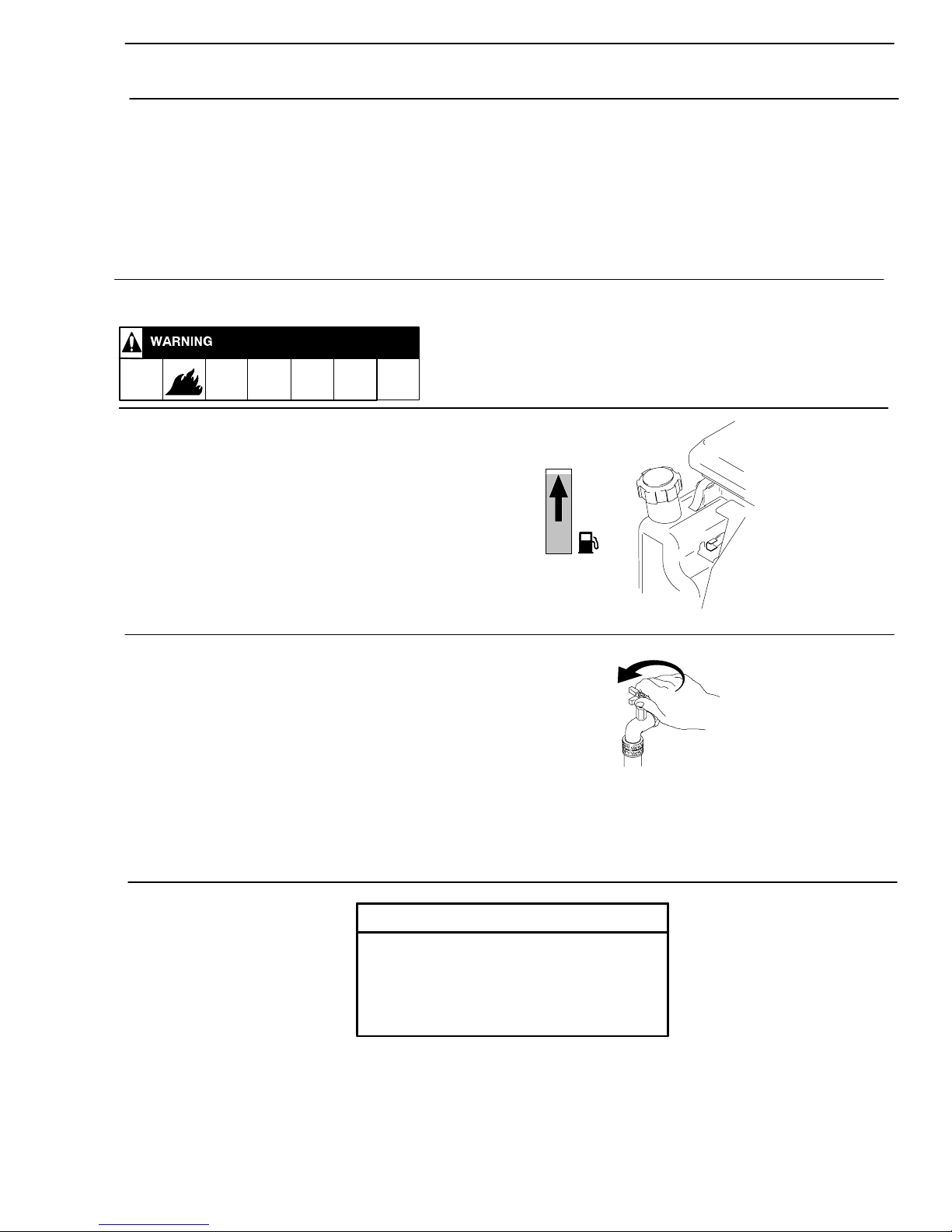
Fuel Hazard:
Fuel is combustible. When spilled on a hot surface it can ignite and cause a fire.
Do not fill fuel tank while engine is running or hot.
Exhaust Hazard:
Exhaust contains poisonous carbon monoxide, which is colorless and odorless. Do not operate this
equipment in a closed building.
3309882

4309882
Component Identification
Gun and Wand
High Pressure
Hose Connection
On/Off Engine Switch (side)
Water Pump Oil Fill
Engine Oil Fill
Tip Storage Hose Rack (a) /
Gun Holder (b)
(b) (a)
Garden Hose
Connection
Pressure Unloader
Adjustment Knob
ti3226a
Thermal Valve

5309882
Shipping Damage
Check pressure washer for shipping damage. Notify carrier immediately if there is any damage.
Setup
Connect High–Pressure Hose and Gun
Connect high–pressure hose between the pump outlet and gun inlet.
Install Spray Tip
Install spray tip on wand. Installing and Changing Spray Tips,
page 11). If you are using a Sandblasting Kit, see its separate
manual for installation instructions.
Connect to Water Supply
Connect hose with at least a 3/4 in. (19 mm) ID from water supply
to 3/4 in. garden hose inlet on the pressure washer. The supply
hose should not be more than 50 ft (15 m) long.
Before you connect garden hose to pres-
sure washer, check local plumbing codes
regarding cross–connection to water
supply. If required, install backflow pre-
venter.
If inlet water pressure is over 60 psi (4.1
bar), a regulating water valve must be
installed at garden hose connection.
Do not exceed 104°F (40°C) inlet water
temperature.
CAUTION
Note: Water source must have a minimum flow rate equal to that of pressure washer.
ti3228a
ti3229a
ti3457a

6309882
PRESSURE RELIEF
Follow these instructions whenever you are instructed to relieve pressure, stop spraying for
more than 10 minutes, check or service the equipment, or install or clean the spray nozzle.
1. Engage trigger safety latch
2. Turn pressure washer off
3. Remove ignition cable from spark plug.
4. Shut off water supply. Disconnect from water.
5. Disengage trigger safety latch. Trigger gun to relieve
pressure. Then re–engage the safety latch.
Note: If you suspect that the spray tip or hose is clogged or that pressure has not been fully relieved after
following the steps above, disengage the trigger safety latch and trigger the gun to relieve pressure.
TI3233A
TI3234a

7309882
1. Check oil level of engine.
Startup
Always use this startup procedure to ensure that the pressure washer is started
safely and properly.
Always engage gun trigger safety latch when you stop spraying. This reduces the risk of fluid injection or
splashing in eyes or on skin if gun is bumped or accidentally triggered.
Always observe the CAUTIONS in this section to avoid costly damage to pressure washer.
If you use the Sandblaster Kit, see Sandblaster Kit Manual for detailed cleaning information.
.
Operation
2. Check fuel level.
3. Turn on water supply.
Never run pressure washer without wa-
ter. Costly pump damage will result.
Always be sure water supply is complete-
ly turned on before you run pressure
washer.
CAUTION

8309882
4. Trigger gun until a constant stream of water sprays from tip indicating air is purged from the system.
5. Be sure spark plug ignition cable is pushed firmly onto spark plug.
6. Move throttle to Rabbit (fast) position and choke to CHOKE
position.
Do not allow pressure washer to idle more than 10
minutes. This causes circulating water to overheat and
serious damage to the pump. The pump is equipped
with a thermal valve to help prevent severe damage if
circulating water is overheating.
Turn off pressure washer if it will not be spraying at
least every 10 minutes or if thermal valve activates. If
heated inlet water is used, reduce this time.
Do not operate pressure washer with inlet water
screen removed. This screen helps keep abrasive
sediment which could clog pump or damage cylinders,
out of pump.
Do not pump caustic materials.
CAUTION
7. Pull the starter rope quickly to start the engine. Pull and return the
rope until the engine starts. HINT: Placing one foot on the pres-
sure washer as a brace provides better leverage.
NOTE: For easier starting, have one person start pressure washer while another triggers gun.
ti3237a
ti3240a
ti3242a

9309882
Trigger Safety Latch
Always engage the safety latch when you stop spraying.
Always engage trigger safety latch when you stop spraying even for a moment. The engaged
safety latch prevents the gun from being triggered accidentally by hand or when dropped or
bumped. Be sure latch is pushed fully down or it will not prevent the gun from being triggered.
Safety ON Safety OFF
TI3234a
TI3233A

10 309882
1. Follow Pressure Relief Procedure, page 6.
Chemical Injector Operation
2. Push end of chemical injector hose over chemical injector fitting on
pump. Place other end in container of chemical solution.
3. Install the black, large–orifice, chemical tip. (Installing and Changing Spray Tips page 11).
4. Trigger gun for a few seconds. Chemical solution will begin mixing in spray pattern.
The large orifice of the chemical tip causes a drop in pressure that actuates the chemical injector.
Changing back to a small orifice spray tip deactivates the chemical injector and produces high pressure
for rinsing. The chemical filter can be left in the chemical container during high–pressure use.
ti3237b

11309882
Spray tips have 4– or 5–digit numbers on them.
The first two digits are the spray angle. Tip
holding holes are provided on the chassis.
1. Perform Pressure Relief Procedure, page 6.
2. Point the gun and wand away from you and anyone else.
3. Lock trigger safety.
4. Without holding your hand over spray tip (A), pull back quick
coupler ring (B). Remove current tip. Install a different one.
Then push the ring back on.
Installing and Changing Spray Tips
Spray Tip
Number
Spray Pattern Fan Angle
00XXX
15XXX
25XXX
40XXX
Chemical
0blaster (red)
15(yellow)
25(green)
40(white)
XX(black)
NOTE: The chemical injector tip is brass and has a large opening and a black plastic cap.
B
A
To avoid blowing the o–ring out of the
quick coupler due to the high pressure in
the system, never operate pressure
washer without a tip securely mounted in
quick coupler.
CAUTION

12 309882
Shutdown, Flushing, and Storage
Do not allow water to freeze in pressure
washer components.
If pressure washer will be exposed to
freezing temperatures, drain all water out
of pump. If it must be stored in freezing
temperatures, flush with a 50% solution
of anti–freeze and relieve pressure.
Flush pressure washer before you use it
again to remove anti–freeze.
CAUTION
1. Remove chemical injector hose from pump, if attached.
2. Trigger gun for one minute to flush pump with clear water.
3. Engage trigger safety.
4. Adjust throttle to STOP position. Engine should turn off.
TI3234a

13309882
5. Shut off water supply. Disconnect water supply hose from pump.
6. Remove trigger safety latch and trigger gun to relieve pressure.
7. Remove high pressure hose from pump. Drain water from all components.
After each use, wipe all surfaces of pressure washer with a clean, damp cloth.
ti3231a
ti3247b

14 309882
Maintenance Chart
Perform Pressure Relief Procedure (page 6).
Interval What to do
Daily Clean water inlet screen and filter. Check engine and pump oil levels. Fill as necessary. Check
gasoline level. Fill as necessary.
After first
5 hours of
operation
Change engine break-in oil. Drain oil when warm. Use SAE 30 or 10W–30 detergent oil.
Every 3
months or
25 hours of
operation
Clean and remove air cleaner foam. Wash with water and detergent. Dry thoroughly. Rub with
oil, and squeeze to distribute oil.
Every 6
months or
50 hours of
operation
Change engine oil. Use Use approved SAE30 or 10W30 detergent oil.
After every
100 hours of
operation, or
every 3 months
Check/adjust spark plug and idle speed. Clean fuel tank and filter..
NOTE: It is not necessary to change pump oil during the life of the pump. If pump oil is drained for repair, use part
number 117784 replacement oil only.

15309882
Troubleshooting
Perform Pressure Relief Procedure (page 6).
Problem Cause Solution
Engine will not start or
is hard to start.
No gasoline in fuel tank or carburetor Fill tank with gasoline, open fuel shutoff valve.
Check fuel line and carburetor.
Low oil Add oil to proper level.
Throttle in STOP position Move throttle to FAST (rabbit) position
Water in fuel or old fuel Drain fuel tank and carburetor. Use new fuel
andmake sure spark plug is dry.
Engine flooded or improperly choked Open choke, pull engine starter rope several
times to clear out fuel. Make sure spark plug
is dry.
Dirty air cleaner filter Remove and clean.
Spark plug dirty, wrong gap, or wrong
type
Clean, adjust gap or replace.
Gun not triggered Trigger gun while starting engine.
Engine misses or
lk
Partially plugged air cleaner filter Remove and clean.
lacks power Spark plug dirty, wrong gap, or wrong
type
Clean, adjust gap or replace.
Pressure is too low
d/
Worn or wrong size tip Replace with tip of proper size.
and/or pump runs
roughly
Inlet filter clogged Clean. Check more frequently.
roughly
Worn packings, abrasives in water, or
natural wear
Check filter. Replace packing.
Inadequate water supply Check water flow rate to pump.
Fouled or dirty inlet or discharge valves Clean inlet and discharge valve assemblies.
Check filter.
Restricted inlet Garden hose might be collapsed or kinked.
Worn inlet or discharge valves Replace worn valves.
Leaking high–pressure hose Replace high–pressure hose.
Water leaks from
difld
Worn packings Install new packings.
under pump manifold Loose fitting connections Check all fitting connections. Tighten if loose.
Water on oil side of Worn packings Install new packings.
pump Oil seals leaking Install new oil seals.

16 309882
Problem Cause Solution
Packings are failing
freq entl or
Scored, damaged, or worn plungers Install new plungers.
frequently or
p
r
e
m
atu
r
e
l
y
Abrasive material in fluid being pumped Install proper filtration on pump inlet plumbing.
prematurely
Inlet water temperature too high Check water temperature. It should not
exceed 104F (40C).
Overpressurizing pump Do not modify any factory–set adjustments.
Excessive pressure due to partially
plugged or damaged tip
Clean or replace tip. See Installing and
Changing Spray Tips (page 11).
Pump running too long without spraying Never run pump more than 10 minutes without
spraying.
Running pump dry Do not run pump without water.
Strong surging at inlet
and low pressure on
discharge side
Foreign particles in inlet or discharge
valve or worn inlet and/or discharge
valves
Clean or replace valves.
Water spitting out of
thermal valve
Pump running too long without spraying Trigger gun to get fresh, cooler water in pump.

17309882
Pump Service
Repair kits are available. See the Parts Lists (page 20). For the best results, use all parts in the kits.
Perform Pressure Relief Procedure (page 6).
Servicing Valves
Discharge Valves:
Disassembly
1. Remove valve cap.
2. Inspect valve cap o–ring for damage. Replace if
necessary.
3. Using a needle nose pliers, remove valve.
4. Use a small probe to move the poppet up and down
to assure it is functioning properly.
5. Inspect for any debris that may be lodged between
poppet and seal.
6. Remove valve seat o–ring and inspect for damage.
Assembly
1. Install valve seat o–ring squarely into bottom of
manifold.
2. Insert valve assembly squarely into port, pushing it
into o–ring.
3. Install valve cap and torque to 443 in.–lbs (37
ft–lbs).
Inlet Valves
Disassembly
1. Remove manifold.
2. Remove low–pressure seals by inserting a flat
screwdriver under seal lip and lifting up.
3. Using a reversible pliers, carefully remove packing
retainers (plunger guides).
Note: Packing retainers can be reused if not worn.
4. Remove high–pressure packing by pulling straight
out with your finger.
5. Pull out valve cage/head ring assembly, valve
poppet, spring and o–ring.
6. Inspect for debris and/or damage.
7. Remove valve o–ring.
Assembly
1. Install valve seat o–ring squarely into bottom of
manifold.
2. Insert valve assembly and push squarely into o–
ring.
3. Install high–pressure packing by placing it into
cylinder at an angle and then pushing into place.
Note: The point of the “v” or flat side of packing is
pointed at you.
4. Lubricate packing retainer o–ring with a light film of
oil and install it into cylinder.
5. Push it completely into place.
Note: O–ring will seat just inside manifold and you will
hear a slight pop.
6. Insert low–pressure seal by placing it into cylinder at
an angle and pushing it into place.
7. Put a thin coat of oil on plungers and packings.
8. Carefully install manifold and torque bolt to 443
in.–lbs (37 ft–lbs).
Note: Valve life is dependant on many variables.
Hard water, cavitation, corrosion, chemicals and
equipment care. The valves are a wear item and need
periodic replacement. Worn o–rings or damaged
valves will cause pressure loss and pulsations.

18 309882
Packings
Disassembly
1. To access water seals for inspection or replacement,
remove head of pump.
Note: It is important to note the order in which the
components of the packing stack are arranged and
facing during disassembly.
2. Remove head bolts.
3. Insert a small pry bar between head and body at
opposite corners and apply pressure down on one
pry bar and up on the other pry bar.
4. Lift head up and away from body.
Note: Packing stack will not always stay in head of
pump when it is removed. Sometimes one or more
components of the packing stack will come out of the
head and stay on the plunger.
5. To remove any components that stay on plungers
twist back and forth while pulling up.
6. Remove low–pressure seals by inserting a flat
screwdriver under seal lip and lifting up.
7. Remove piston guides from head by using a reverse
pliers (preferably rubber coated) inserted into
center of piston guide.
8. Use back and forth twisting motion while pulling up
(clockwise and counter–clockwise).
9. Another method is to use a two–prong slide hammer
puller. Insert prongs into piston guide allowing
prongs to grab under support ring, then use slide
hammer to pull packing stack up and out of head.
Note: Damage to piston guides and or seals may
occur during removal. Inspect carefully before reusing
any components of packing stack.
10. Remove high–pressure packing by pulling straight
out with your finger.
Assembly
1. Install high–pressure seal into head.
Note: It should fit snugly. The packing support is part
of the valve cage.
2. Place high–pressure seal at an angle and work it
into cylinder.
Note: The point of the “v” or flat side of packing is
pointed at you.
3. Lubricate packing retainer o–ring with a light film of
oil and install it into cylinder.
4. Push it completely into place.
Note: O–ring will seat just inside manifold and you will
hear a slight pop.
5. Insert low–pressure seal by placing it into cylinder at
an angle and pushing it into place.
6. Put a thin coat of oil on plungers and packings.
7. Carefully install manifold and torque bolt to 443
in.–lbs (37 ft–lbs).
Note: Valve life is dependant on many variables.
Hard water, cavitation, corrosion, chemicals and
equipment care. The valves are a wear item and need
periodic replacement. Worn o–rings or damaged
valves will cause pressure loss and pulsations.
Water seals are wear items. Lift of seals is dependent
on many factors. Water seals should be replaced
when water leak or loss of performance is noticed.
Prompt replacement of worn seals will insure peak
operating performance and trouble–free operation.

19309882
Notes

20 309882
Parts
43,44
33
21
20 23 24 26
25
4
5
9
36
15
12
34
32
10
1
3
45
22
29
30
28
16
17
14
13
22
8
7
6
2
35
27
ti3218g
31
37
Table of contents
Other ASM Pressure Washer manuals
Popular Pressure Washer manuals by other brands

Briggs & Stratton
Briggs & Stratton SpeedClean 020227-0 owner's manual

Bosch
Bosch GHP 5-13 C Original instructions

Xstream
Xstream X-HW2565AR Operation manual

Nilfisk-Advance
Nilfisk-Advance ALPHA BOOSTER 3 user manual

North Star
North Star M157595BK owner's manual

Graco
Graco Series A Instructions-parts list