2 3
English
1.2 Product Specications
The specification is subject to change without notice. The brand and product names are trademarks of their respective companies. Any configuration other than original product specification is not guaranteed.
Environment
Operating Temp
Storage Temp
Operating Humidity
Storage Humidity
0ºC ~ 40ºC
-40° C – 85° C
5% ~ 90%
5% ~ 90%
Mechanical
Construction
Mounting
Dimensions (W x D x H)
Weight
Plastic with sheet metal
VESA mounting
110.0 x 117.5 x 47.85mm
Net Weight:1.0Kg
Audio
Interface Realtek ALC256, High Definition Audio.
Watchdog Timer
Output
Interval
From Super I/O to drag RESETCON#
256 Segments, 0, 1, 2, ...255sec
Ethernet
Controller/ Speed
Connector
Realtek RTL8125BG with 10/100/1000/2500 Mbps
2 x RJ-45
Expansion Slot
M.2/ WLAN 1 x Wi-Fi 6E 802.11ax + BT 5.2
(M.2 Key E, 2230 PCIe Gen3 x1, USB 2.0 for Wireless)
* WiFi throughput speed depends on actual environment
and equipment
Storage
M.2
SATA
1 x M.2(KEY M, 2242/2260/2280) with PCIe Gen3 x1 and SATA3 for SSD
*M.2 Key M 2280(Supported by bracket)
1 x SATA3.0 (6.0 Gb/s)
Power Requirements
Input PWR
Power On
9V~19V DC-In Jack
AT/ATX Supported
- AT : Directly PWR on as power input ready
- ATX : Press button to PWR on after power input ready
‧Intel®Alder Lake-N SoC Processors N97
‧1 x 260-pin SO-DIMM up to 16GB DDR4 3200 MHz
‧5 x USB 3.2 Gen2, 1 x M.2 Key M, 1 x M.2 Key E (WiFi Module), 1 x SATA3
‧2 x Realtek 2.5 Gigabit LAN
‧Supports Triple display, 2 x HDMI 2.0b, 2 x DP 1.4a (from Type C)
‧TPM 2.0 onboard IC
‧19V/65W Power Adapter
‧110.0 x 117.5 x 47.85mm, Fanned Barebone
Memory
Technology
Capacity
Socket
Single Channel DDR4 3200 MHz
16GB
1 x 260-pin SO-DIMM
Processor System
CPU
Chipset
BIOS
Intel®Alder Lake-N SoC Processors N97
MCP
AMI SPI 256 Mbit
Graphics
Controller
HDMI
DisplayPort
MultiDisplay
Intel®Gen 12 Graphics
HDMI 2.0b
Max resolution up to 4096x2160@60Hz
DisplayPort 1.4a, DP++
Max resolution up to 4096x2160@60Hz
Triple-Display (Included 2 outputs from Type-C)
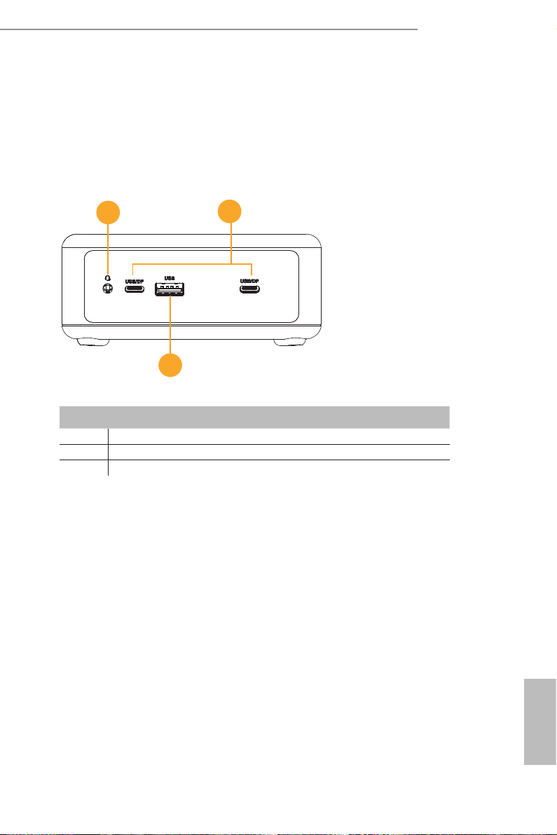
Front I/O
USB
Audio
1 x USB 3.2 Gen2 (Type A)
2 x USB 3.2 Gen2 (Type-C, 5V/3A, Supports DP1.4a display output)
1 (headphone & microphone jack)
Rear I/O
HDMI
Ethernet
USB
DC Jack
2 x HDMI 2.0b
2 x 2.5 Gigabit LAN
2 x USB 3.2 Gen2 (Type-A)
1
Others
OS Support
TPM
Certifications
Packing List
Windows 10/11
TPM 2.0 onboard IC
CE, FCC
1 x 19V/65W Power Adapter
1 x Screw Package
1 x VESA mounting bracket
Fanned BOX
NUC N97 BOX Series
SPECIFICATIONS
KEY FEATURES
The specification is subject to change without notice. The brand and product names are trademarks of their respective companies. Any configuration other than original product specification is not guaranteed.
Environment
Operating Temp
Storage Temp
Operating Humidity
Storage Humidity
0ºC ~ 40ºC
-40° C – 85° C
5% ~ 90%
5% ~ 90%
Mechanical
Construction
Mounting
Dimensions (W x D x H)
Weight
Plastic with sheet metal
VESA mounting
110.0 x 117.5 x 47.85mm
Net Weight:1.0Kg
Audio
Interface Realtek ALC256, High Definition Audio.
Watchdog Timer
Output
Interval
From Super I/O to drag RESETCON#
256 Segments, 0, 1, 2, ...255sec
Ethernet
Controller/ Speed
Connector
Realtek RTL8125BG with 10/100/1000/2500 Mbps
2 x RJ-45
Expansion Slot
M.2/ WLAN 1 x Wi-Fi 6E 802.11ax + BT 5.2
(M.2 Key E, 2230 PCIe Gen3 x1, USB 2.0 for Wireless)
* WiFi throughput speed depends on actual environment
and equipment
Storage
M.2
SATA
1 x M.2(KEY M, 2242/2260/2280) with PCIe Gen3 x1 and SATA3 for SSD
*M.2 Key M 2280(Supported by bracket)
1 x SATA3.0 (6.0 Gb/s)
Power Requirements
Input PWR
Power On
9V~19V DC-In Jack
AT/ATX Supported
- AT : Directly PWR on as power input ready
- ATX : Press button to PWR on after power input ready
‧Intel®Alder Lake-N SoC Processors N97
‧1 x 260-pin SO-DIMM up to 16GB DDR4 3200 MHz
‧5 x USB 3.2 Gen2, 1 x M.2 Key M, 1 x M.2 Key E (WiFi Module), 1 x SATA3
‧2 x Realtek 2.5 Gigabit LAN
‧Supports Triple display, 2 x HDMI 2.0b, 2 x DP 1.4a (from Type C)
‧TPM 2.0 onboard IC
‧19V/65W Power Adapter
‧110.0 x 117.5 x 47.85mm, Fanned Barebone
Memory
Technology
Capacity
Socket
Single Channel DDR4 3200 MHz
16GB
1 x 260-pin SO-DIMM
Processor System
CPU
Chipset
BIOS
Intel®Alder Lake-N SoC Processors N97
MCP
AMI SPI 256 Mbit
Graphics
Controller
HDMI
DisplayPort
MultiDisplay
Intel®Gen 12 Graphics
HDMI 2.0b
Max resolution up to 4096x2160@60Hz
DisplayPort 1.4a, DP++
Max resolution up to 4096x2160@60Hz
Triple-Display (Included 2 outputs from Type-C)
Front I/O
USB
Audio
1 x USB 3.2 Gen2 (Type A)
2 x USB 3.2 Gen2 (Type-C, 5V/3A, Supports DP1.4a display output)
1 (headphone & microphone jack)
Rear I/O
HDMI
Ethernet
USB
DC Jack
2 x HDMI 2.0b
2 x 2.5 Gigabit LAN
2 x USB 3.2 Gen2 (Type-A)
1
Others
OS Support
TPM
Certifications
Packing List
Windows 10/11
TPM 2.0 onboard IC
CE, FCC
1 x 19V/65W Power Adapter
1 x Screw Package
1 x VESA mounting bracket
Fanned BOX
NUC N97 BOX Series
SPECIFICATIONS
KEY FEATURES