2
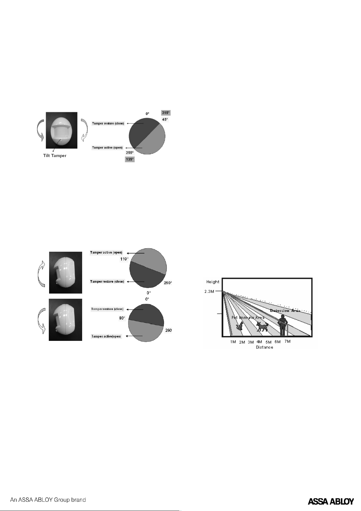
Understanding the Tilt Tamper Detection
Mechanism
• When the PIR is placed on its back, and the tilt
is horizontal: a “Tamper activate" signal will be
transmitted to the control panel. The tilt tamper
will also trigger when the PIR is rotated clockwise
at an angle equal to or greater than 45°, or if the
counter clockwise angle is equal to or greater than
135°. Once the tilt angle is restored to less than 45°
clockwise or 135° counter clockwise, then a “tamper
restore” signal will be transmitted to the control
panel.
• When the PIR is placed upright, and the tilt is
vertical: a “tamper activate”signal will be transmitted
to the control panel when the“learn/test” button is
rotated towards you at an angle equal to or greater
than 110°, or away from you at an angle equal to or
greater than 80°. Once the tilt angle is restored to
less than 110°/80° respectively, a “tamper restore”
signal will be transmitted to the control panel.
Getting Started
• Remove the battery insulator and you are ready to
do the learning process.
• The LED indicator steadily ashes for 30 seconds (PIR
is warming up). During the warming up period, the
PIR will not be activated. It is recommended that you
stay away from the detection area during this time.
After the warming up period is over, the light will
turn o and the PIR will be ready for operation.
• Put the control panel into learn mode and learn-in
the PIR by pressing the“learn/test” button. Please
refer to section “Add/Delete Device” in the operation
manual of the control panel.
• After the PIR is learnt-in, put the control panel
into “Walk Test” mode, hold the PIR in the desired
location, and press the test button to conrm that
this location is within the signal range of the control
panel.
• When you are satised that the PIR works in the
chosen location, you can proceed to install.
Mounting Method
• The PIR is designed to be mounted on either a at
surface or in a corner with the xing screws and
plugs provided.
• The base has drill-outs, where the plastic is thinner,
for mounting purposes. Two drill-outs are for at
xing and four drill-outs are for left or right hand
corner xing.
• To mount the PIR, drill through the appropriate drill-
outs. Using the holes in the housing as a template,
drill holes into the mounting surface and insert the
wall plugs if securing to a brick wall.
Installation
• Decide on the location of the PIR and if it is to be
corner or at mounted.
• Hold the PIR and press the test button to enter test
mode for 3 mins. This is to disable the“Sleep Timer”
and enable the LED indicator to light every time
movement is detected.
• Walk around the protected area, noting when the
LED ashes, and check that the detection coverage
is adequate.
• When you are satised with the detection coverage,
remove the cover by loosening the button xing
screw.
• Screw the base to the wall.
• Screw the cover on. Installation is now complete.
Installation Recommendations
The PIR is designed to give a typical detection range of
12 meters when mounted at 2 meters above ground.
When mounted at 2.3 meters above ground, it gives
a typical pet immune range of 7 meters. The higher
the PIR is mounted above ground, the better the pet
immunity range.
To take full advantage of the PIR, the following
guidelines should be considered:
• It is recommended to install the PIR at the following
heights
• 2.1 - 2.4 m above ground for best performance