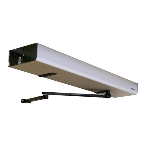
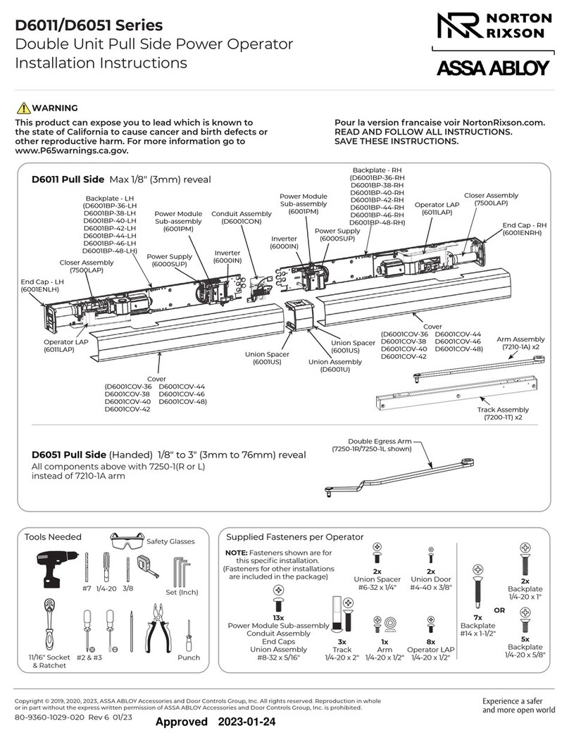
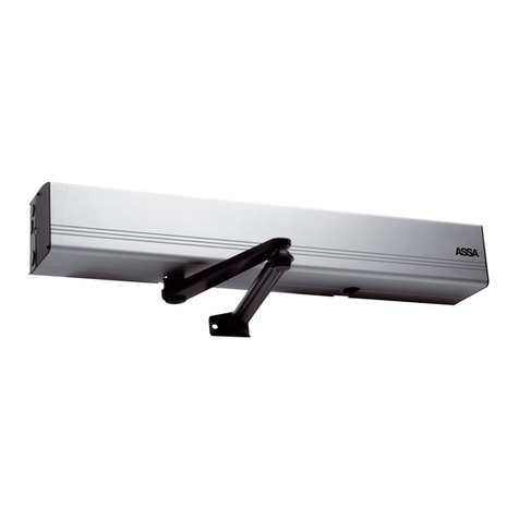
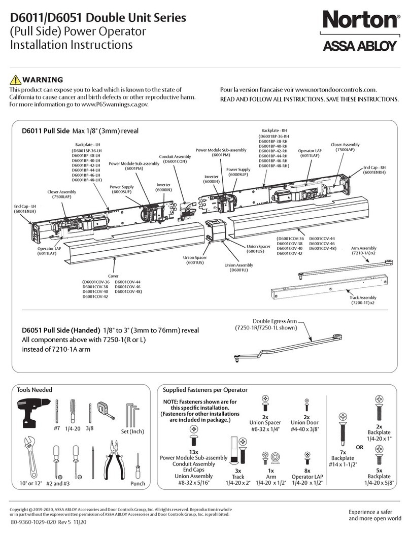
Assa Abloy Besam PowerSwing CSDB Manual

ASSA ABLOY, the global leader in door opening solutions
1004935-US-1.0 – Issue 2008-11-13
ILL-01558
Besam Swing Door Operator
PowerSwing (CSDB)
Installation and Service Manual

2 Issue 2008-11-13 1004935-US-1.0
© All rights in and to this material are the sole property of ASSA ABLOY Entrance Systems AB. Copying, scanning, alter-
ations or modifications are expressly forbidden without the prior written consent of the applicable company within ASSA
ABLOY Entrance Systems AB. Rights reserved for changes without prior notice.

1004935-US-1.0 Issue 2008-11-13 3
1 Revision . . . . . . . . . . . . . . . . . . . . . . . . . . . . . . . . . . . . . . . . . . . . . . . . . . . . . . . . . . . . .4
2 Important information. . . . . . . . . . . . . . . . . . . . . . . . . . . . . . . . . . . . . . . . . . . . . . . . . . .5
3 Introduction . . . . . . . . . . . . . . . . . . . . . . . . . . . . . . . . . . . . . . . . . . . . . . . . . . . . . . . . . .6
4 Technical specifications. . . . . . . . . . . . . . . . . . . . . . . . . . . . . . . . . . . . . . . . . . . . . . . . .7
5 How the PowerSwing works. . . . . . . . . . . . . . . . . . . . . . . . . . . . . . . . . . . . . . . . . . . . . .8
6 Models . . . . . . . . . . . . . . . . . . . . . . . . . . . . . . . . . . . . . . . . . . . . . . . . . . . . . . . . . . . . .14
7 Part identification . . . . . . . . . . . . . . . . . . . . . . . . . . . . . . . . . . . . . . . . . . . . . . . . . . . . .15
8 Options. . . . . . . . . . . . . . . . . . . . . . . . . . . . . . . . . . . . . . . . . . . . . . . . . . . . . . . . . . . . .16
9 Pre-Installation. . . . . . . . . . . . . . . . . . . . . . . . . . . . . . . . . . . . . . . . . . . . . . . . . . . . . . .21
10 Mechanical installation. . . . . . . . . . . . . . . . . . . . . . . . . . . . . . . . . . . . . . . . . . . . . . . . .24
11 Electrical Connection . . . . . . . . . . . . . . . . . . . . . . . . . . . . . . . . . . . . . . . . . . . . . . . . . .32
12 Start-Up . . . . . . . . . . . . . . . . . . . . . . . . . . . . . . . . . . . . . . . . . . . . . . . . . . . . . . . . . . . .36
13 Cover . . . . . . . . . . . . . . . . . . . . . . . . . . . . . . . . . . . . . . . . . . . . . . . . . . . . . . . . . . . . . .39
14 Signage and Safety equipment . . . . . . . . . . . . . . . . . . . . . . . . . . . . . . . . . . . . . . . . . .40
15 Troubleshooting . . . . . . . . . . . . . . . . . . . . . . . . . . . . . . . . . . . . . . . . . . . . . . . . . . . . . .41
16 Maintenance plan . . . . . . . . . . . . . . . . . . . . . . . . . . . . . . . . . . . . . . . . . . . . . . . . . . . .42
Table of content

4 Issue 2008-11-13 1004935-US-1.0
1Revision
Following pages have been revised:
Page Revision
– This is the first version of Installation and Service Manual for Swing Door
Operator PowerSwing (CSDB), No. 1004935-US-1.0, Issue 2008-11-13

1004935-US-1.0 Issue 2008-11-13 5
2 Important information
2.1 Important notice
To avoid bodily injury, material damage and malfunction of the product, the instruc-
tions contained in this manual must be strictly observed during installation, adjust-
ment, repairs and service etc. Only Besam-trained technicians should be allowed to
carry out these operations. Save these instructions.
2.2 Electronic equipment reception interference
This equipment may generate and use radio frequency energy and if not installed and
used properly, that is, in strict accordance with the manufacturer's instructions, it may
cause interference to radio, television reception or other radio frequency type sys-
tems. It has been designed to comply with the emission limits in accordance with EN
61000-6-3 (US market FCC Part 15), which are designed to provide reasonable pro-
tection against such interference in a residential installation.
However, there is no guarantee that interference will not occur in a particular installa-
tion. If this equipment does cause interference to radio or television reception, which
can be determined by turning the equipment off and on, the user is encouraged to try
to correct the interference by one or more of the following measures:
• Re-orient the receiving antenna.
• Relocate the receiver with respect to the equipment.
• Move the receiver away from the equipment.
• Plug the receiver into a different outlet so that equipment and receiver are on dif-
ferent branch circuits.
• Check that protective earth (PE) is connected.
If necessary, the user should consult the dealer or an experienced electronic techni-
cian for additional suggestions.
2.3 Environmental requirements
Besam products are equipped with electronics and may also be equipped with batter-
ies containing materials which are hazardous to the environment. Remove this mate-
rial from the operator before it is scrapped and make sure that it is disposed of safely
as was done with the packaging.

6 Issue 2008-11-13 1004935-US-1.0
3 Introduction
This manual contains the necessary details and instructions for the installation, main-
tenance and service of the Besam PowerSwing.
The Besam PowerSwing is suitable for most types of external and internal swing
doors. The operator can be mounted to walls on either side of the door for pull or
push action and is suitable for single or double doors fitted with butt hinges or pivots.
It can also be installed on the door leaf.
The motor, oil pump and hydraulic unit are combined into a compact unit mounted
alongside the control unit within the cover. The operator is connected to the door leaf
with a range of different arm systems.
Each installation is, however, unique and must therefore be equipped and adjusted for
the application-relevant safety requirements, just like maintenance must be per-
formed as specified for the selected product in a given environment.

1004935-US-1.0 Issue 2008-11-13 7
4 Technical specifications
This product is to be installed internally.
Mains power supply 120 V AC ±10%, 60 Hz
fuse 10 A
Note!
A readily accessible switch with clearly marked OFF-position,having
a contact separation of at least 1/8" in all poles, must be incorporated
in the fixed wiring in accordance with local codes.
Power consumption max. 230 W
Auxiliary voltage 24 V DC, 700 mA (stabilized)
Motor fuse F1 10 Amp (10 ATH)
Control fuse F2 1/2 Amp (500 mAT)
Recommended
max. door weight Arm system PUSH: 550 lb for door leaf width 63"
Arm system PULL: 220 lb for door leaf width 55"
Higher door weights on request
Standards The PowerSwing complies with ANSI/BHMA A156.10, A156.19,
UL325/CUL325
Door opening angle: Push arm: 80° - 120°, with reveal 0 - 19"
Pull arm: 80° - 120°, with reveal 0 - 5 1/8"
Opening time (0° - 80°) variable between 2 to 6 seconds
Closing time (90° - 10°) variable between 2 to 6 seconds
Hold Open Time (HOT) variable between 0 to 30 seconds
Ambient temperature +5°F to +86°F
Relative humidity
(non-condensing) max. 85%
Dimensions Length: PowerSwing (standard cover) 51", 88"
Height: 4 11/32"
Depth: 5 1/8"
Class of protection IP 20
1 1/2’’
5 1/8’’
11/2’’ 11/2’’13/8’’
4 5/16’’
5/8’’
ILL-02015

8 Issue 2008-11-13 1004935-US-1.0
5 How the PowerSwing works
The PowerSwing works electro-hydraulically. It opens with an AC-motor that
through a hydraulic unit and an arm system transmits the power to the door leaf. The
closing power is from a coil spring. The movement of the door is controlled by limit
switches and valve screws.
5.1 Opening
When an opening impulse is received by the control unit, the motor starts and the
hydraulic unit rotates the drive shaft and arm system, causing the door to open at a
high rate of speed. Before reaching the fully open position, the speed is reduced to
low speed. The door stops and the motor rotation ceases when the selected door
opening angle is reached. The open position is held by a hydraulic valve.
5.2 Closing
The spring closing starts when the hold open time has expired. Before reaching the
fully closed position the speed is reduced to low speed, which continues until the
door is completely closed. The door is held closed by spring power. To overcome the
resistance of a strike plate a “lock kick” can be adjusted to meet the requirements of
most installations.
5.3 Functions on the Control Unit CSDB
5.3.1 Key Impulse
Key impulse will open the door in program mode selections OFF, EXIT and AUTO
and will keep the door open during key hold open time.
Key impulse hold open time can be adjusted between 0 to 30 sec.
5.3.2 Outer Impulse
Outer impulse will open the door if the Program Selector is set to AUTO therefore
keeping the door open during the outer hold open time, which can be adjusted
between 0 to 30 s.

1004935-US-1.0 Issue 2008-11-13 9
5.3.3 Multi Voltage Input (MVI)
MVI impulse accepts a dry (no voltage) contact or 6-24 V AC/DC.
Status of lock (operation mode) can be selected through a function selector FS2
which depends on input TB2:11 and 13.
* +6-24 V DC must be connected to TB2:13.
Program selector must not be connected to TB2:13 if input is 6-24 V. Instead, con-
nect program selector to EXB.
MVI impulse will unlock the lock and open the door or only unlock the lock
(changes the operation mode of the operator), when using the function selector FS3.
MVI hold open time can be adjusted between 0 to 30 sec.
FS-2 = OFF (factory setting)
FS-3 = OFF (factory setting) TB2:11 and 13 TB2:11 and 13 TB2:11 and 13
6-24 V AC/DC*
CSDB (No PS)
OFF
AUTO
EXB OFF OFF
EXB EXIT EXIT
EXB AUTO AUTO
EXB OPEN OPEN
FS-2 = ON
FS-3 = OFF (factory setting) TB2:11 and 13 TB2:11 and 13 TB2:11 and 13
6-24 V AC/DC*
CSDB (No PS) AUTO
OFF
EXB OFF OFF
EXB EXIT EXIT
EXB AUTO AUTO
EXB OPEN OPEN
FS-2 = OFF (factory setting)
FS-3 = ON TB2:11 and 13 TB2:11 and 13 TB2:11 and 13
6-24 V AC/DC*
CSDB (No PS) OFF Open door
EXB OFF OFF Open door
EXB EXIT EXIT Open door
EXB AUTO AUTO Open door
EXB OPEN OPEN Open door
FS-2 = ON
FS-3 = ON TB2:11 and 13 TB2:11 and 13 TB2:11 and 13
6-24 V AC/DC*
CSDB (No PS) Open door OFF
EXB OFF Open door OFF
EXB EXIT Open door EXIT
EXB AUTO Open door AUTO
EXB OPEN Open door OPEN

10 Issue 2008-11-13 1004935-US-1.0
5.3.4 Kill Input
When Kill mode is activated, the door will close immediately if not already closed.
Hold open and low pass filter timers are reset.
Key impulse will activate lock when kill is activated if key impulse 0 VDC is not con-
nected to TB2:5.
When Kill mode is deactivated, the door will act according to one of the current input
statuses.
Several Kill mode inputs are possible to connect in parallel with other CSDB control
units. Connect to Kill electrical lug on first operator according to the connection dia-
gram. The second, third etc. operator is only to be connected in parallel, from terminal 5
to 5 and 6 to 6.
Kill Function is selected through the function selector FS1 (Kill Jumper).
5.3.5 Open Limit Switch
The Open Limit Switch indicates a fully open door and can be adjusted for opening
angles up to 120º.
When the Open Limit Switch is activated the motor will stop. If the open limit switch
is not activated, the motor will stop 10 seconds after an activation impulse is
received.
If the limit switch is deactivated when the door is open, the motor will restart to repo-
sition the door.
The illuminated LED indicates an activated limit switch.
Contact rating: 1A, 48 V DC, normally open.
5.3.6 Home Switch (optional)
When no home switch is installed and the open limit switch is deactivated (when the
door is closing) and no activation impulse received, a timer starts and after 6 sec. the
status will change from Close to Closed Door.
If the optional Home Switch is mounted, this will indicate closed door instead of the
timer.
“Opening Delay” for lock (0 to 3s) is ignored as soon as Home Switch is not activated.
“Slave Delay” (0,5s) is ignored as soon as home switch for the master is not acti-
vated.
Presence impulse is ignored when Home Switch indicates a closed door within 6 sec-
onds.
The LED indicates an activated Home Switch.

1004935-US-1.0 Issue 2008-11-13 11
5.3.7 Lock Output
The Lock Output is short circuit proof and can source a lock with 24V, 375 mA.
The output can be locked with power or locked without power. It can be selected
through the Function Selector FS4 (Locked w. / w.o. power).
The lock activation time can be either 1,5 s + opening delay or until closing. It can be
selected through the function selector FS5 (Lock time 1,5 s/until closing).
“Opening Delay” for lock, the time that will pass before the motor starts, can be
adjusted from 0 to 3 s.
If a home switch is installed, the lock opening time will first start when the home
switch is deactivated. This prevents the door from jamming in the lock if the presence
detection is activated.
5.3.8 Double Door
The CSDB on the Slave Unit must be configured as a slave. This can be selected
through the function selector FS7 (Master / Slave).
To prevent the thicker door panels from jamming, a delay of 0,5 sec. can be selected
through Function Selector FS6 (Slave Delay). A Home Switch is recommended to
prevent an open delay, if a activation impulse should be received while closing.
5.3.9 Push to Go
A push or pull on the door from Closed Position will start an automatic opening cycle
if the program selection is AUTO or EXIT, and remain open during the hold open
time “Outer HOT” (0 to 30 s).
A home switch on the operator is needed to achieve Push to Go and the Function
Selector FS8 (Push to Go) must be set to ON.
The LED indicates when the Home Switch is active.
5.3.10 Error Messages
The LED indicates sensor error; 1 flash of 0,2 sec. and then 1 sec. pause etc.
5.3.11 Program Selector
Program Selector PS-3B, having three positions (OFF-AUTO-OPEN) can be con-
nected to the CSDB.
Note! If the MVI-input is used for 6-24 V, the PS-3B can not be used.
The key impulse will work even in program selection OFF position.
Presence sensors are enabled in all Program Selector settings, unless in the Kill Mode
of operation.

12 Issue 2008-11-13 1004935-US-1.0
5.4 Functions on the Extension Unit EXB
5.4.1 Inner Impulse
Inner impulse will open the door if Program Selection is set to AUTO or EXIT and
keep the door open during the hold open time.
The hold open time is adjustable from 0 to 30 sec.
5.4.2 Low Pass Filter (automatic cycle delay)
This function is used in Europe for handicap individuals who want to use an auto-
matic door. This function requires the individual to push and hold or maintain the
inner impulse signal for a specified amount of time to automatically open the door.
The time can be adjusted from 0 to 5 sec.
5.4.3 Presence Impulse Approach, Door Mounted
Presence Impulse will prevent an open door from closing and will re-open a closing
door.
Presence impulse is ignored when home impulse is active.
Presence impulse is ignored if the door is manually opened.
Presence impulse is not ignored if the door is opened with Push to Go.
The input can be either “normally open” or “normally closed”, which can be selected
through a function selector jumper (Presence Impulse NO/NC).
5.4.4 Presence Detection Swingpath, Door Mounted
Presence Detection prevents a closed door from opening and stop a door from con-
tinuing to open.
A switch can be used to blank out / inhibit the sensor from detecting a wall or object
close to the open door. In addition, a second switch can be added to extend the inhibit
zone.
Two LED’s indicate the blank out/inhibit switch status. One LED for the master door
and one for the slave door. The LED will illuminate if either of the two blanking/
inhibit switches are activated.
Presence detection can be selected through two function selectors jumpers, “Presence
Detect Master” and “Presence Detect Slave”.

1004935-US-1.0 Issue 2008-11-13 13
5.4.5 Sensor Monitoring
Monitoring can be selected through a function selector jumper (Presence Sensor Moni-
toring).
Test of Presence Detection is performed before opening. Test of Presence Impulse is
performed before closing. The Master Sensors are tested first and the slave sensors
are tested when the answer is received from Master Sensors.
If sensor test is not performed successfully the door will enter Manual Mode and
report sensor error. The sensor test will continue during manual mode.
It is only possible to monitor sensors with a normally closed (NC) output.
If the sensor error disappears during manual mode the door will re-enter automatic
mode again.
5.4.6 Overhead Presence Detection (OPD)
OPD impulse will prevent a closed door from opening and an open door from closing.
A moving door will ignore the OPD input. The OPD will be active 6 seconds after the
door has started to close. If a home switch is installed, the OPD will be active as soon
as the door is closed.
OPD can be selected through a function selector jumper (Sensor type OPD/Mat).
5.4.7 Mat Safety
Mat safety impulse will prevent a closed door from opening and an open door from
closing.
No impulses are accepted during closing if mat is activated.
Mat safety can be selected through a function selector jumper (Sensor type OPD/
Mat).
5.4.8 LockOut
LockOut is used to ignore the OPD sensor during opening and closing. Output will be
low (0 V DC) when the door is considered closed, high during opening and open and
toggling when the door is closing.
LockOut output will be low (0 V DC) when the door is manually opened.
5.4.9 Program selector
Program Selector PS-4C can be connected to the EXB.
The PS-4C, compared to PS-3B, has a fourth position EXIT that will make the CSDB
ignore the outer impulse device.
Presence sensors are enabled in all Program Selector settings but not when Kill Mode
has been activated.

14 Issue 2008-11-13 1004935-US-1.0
6 Models
Two main models of the PowerSwing are available:
• Single Operator
• Double Operator
The operators are non-handed and not dependent on the hinges. The operators can be
used on both pushing and pulling arm systems.
6.1 Single Operator
The product is delivered complete with back plate, control unit, end plates and cover.
Length including end plates, L = 51" or 88".
Pushing arm system shown.
6.2 Double Operator (Consult Product Order form for availability)
The product is delivered complete with back plate, control unit, end plates and cover.
Cover length L is optional.
Two operators can be mounted under the same cover to open one door each.
Pushing and pulling arm system shown (double egress).
L
ILL-00448
L
ILL 00449

1004935-US-1.0 Issue 2008-11-13 15
7 Part identification
Item No. P/N Description
1 173721 Hydraulic unit 100/120 V AC,
complete with motor, pump and spring tube
2 — Motor / Pump
3 — Spring tube
4 655580 Mains connection harness, 100/120 V
4a 714254 Fuse 0.5 AT slow, 120 V
4b 715236 Fuse 10 ATH slow, 120 V
5 1004204 Control unit CSDB, 120 V AC
1004116 Extension unit EXB (see page 18)
6 655600 Capacitor (25 µF) 120 V, complete
7 1004117 3-position switch, PS-3B for CSDB (see page 18)
8 1003542 Top end plate
9 655614 Limit switch, L = 19 3/4" (see page 18)
1004205 Limit switch, L = 78 3/4" for double doors (see page 18)
10 1003882 Vibration absorbers at hydraulic unit and magnetic oil plug
11 1004417 Cover profile - State L and surface treatment
12 1003545 Fill cover
13 1004418 Back plate - State L and surface treatment
14 1003543 Bottom end plate
ILL-01559
4b
4a
11
8
8
4
3
13
9
7
5
1
2
14
6
10
10
12

16 Issue 2008-11-13 1004935-US-1.0
8Options
8.1 Arm systems
8.1.1 Arm System, PUSH, Heavy Duty Arm / Hybrid
These arm systems are delivered with drive arm, telescopic part and door fitting.
They are used if the operator is installed on the wall on the opposite side of the door
swing and approved for fire door applications.
8.1.2 Arm System, PULL
This arm system is delivered with drive arm, guide shoe and door fitting.
It is used if the operator is installed on the wall on the same side as the door swing,
for example the door is pulled open.
8.1.3 PUSH / SAS-F Arm Extensions
Reveal = X Extension/Joint part P/N
Up to 4 3/8" None (standard arm) – –
4 3/8" to 9 1/4" 13 9/16" 21-06-173005
9 1/4" to 14 1/8" 9 1/16" + Joint part 21-06-173004
21-06-173191
14 1/8" to 19" 13 9/16" + Joint part 21-06-173005
21-06-173191
PUSH: P/N: 173099BK
Heavy Duty Arm / Hybrid: P/N: 21-06-173383
AAE346
PULL P/N: 100125 BK
+
+
X

1004935-US-1.0 Issue 2008-11-13 17
8.1.4 Reveal Spacer, PULL
8.1.5 Drive Shaft Extension Kits
8.2 Tool Kit to change rotation direction
40 mm (1-9/16")
60 mm
(2-3/8")
40 (1-9/16") 60 (2-3/8")
P/N: 173804BK
20 mm
(3/4")
P/N: 21-03-205 P/N: 21-03-206
50 mm
(2")
P/N: 21-03-207
70 mm
(2-3/4")
P/N: 173719

18 Issue 2008-11-13 1004935-US-1.0
8.3 Door Stop
8.4 Limit Switch
8.5 Extension Unit, EXB
8.6 Control Switches
8.6.1 4-Position Switch with Key PS-4C (with EXB)
8.6.2 3-Position Switch PS-3B
P/N: 100147
P/N: 655614 (L = 19 3/4")
P/N: 1004205 (L = 78 3/4")
20 21 22 23 24 25 26 27 28 29 30 31 32 33 34 35 36 37
ILL-02025
P/N: 1004116
ILL-00680
P/N: 655845
P/N: 1004117

1004935-US-1.0 Issue 2008-11-13 19
8.7 Labels
8.8 Push Plates
8.8.1 Push Plates
AUTOMATIC
DOOR
DO NOT
ENTER
AUTOMATIC
DOOR
CAUTION
ILL-00909
PUSH TO
ACTIVATE
PULL TO
ACTIVATE
ACTIVATE
SWITCH TO
OPERATE
P/N: 75-20-100
Dual Side “Automatic Door / Do Not Enter” – (Out)
P/N: 75-20-101
Dual Side “Automatic Door / Do Not Enter” – (In)
P/N: 75-20-102
Dual Side “Caution Automatic Door”
P/N: 1001695
Dual Side “Supervision of child”
P/N: 21-24-006
Push side “Push to Activate”
P/N: 21-24-008
Pull side “Pull to Activate”
P/N: 21-24-007
Dual Side “Activate Switch to Operate”
P/N: 75-02-101
PRESS
TO OPEN
P/N: 75-02-102
P/N: 75-02-107
PRESS
TO OPEN
P/N: 75-02-108
P/N: 75-02-280

20 Issue 2008-11-13 1004935-US-1.0
8.8.2 Remote Transmitter Push Plates
8.8.3 Installation Box for Narrow Plates
8.8.4 Remote Receiver
PUSH
TO OPEN
P/N: 75-02-273
PUSH
TO OPEN
P/N: 75-02-272
PUSH
TO
OPEN
P/N: 75-02-269
PUSH
TO
OPEN
P/N: 75-02-270
P/N: 75-21-002
P/N: USRD433
Table of contents
Other Assa Abloy Garage Door Opener manuals

Assa Abloy
Assa Abloy SW100 Manual

Assa Abloy
Assa Abloy Norton Double D6011 Series User manual

Assa Abloy
Assa Abloy SW100 Manual

Assa Abloy
Assa Abloy Besam SW300 Manual

Assa Abloy
Assa Abloy SL300 User manual

Assa Abloy
Assa Abloy Norton Double D6021 Series User manual

Assa Abloy
Assa Abloy Albany RR1000 User manual

Assa Abloy
Assa Abloy Norton D6001DE-R Double Unit Series User manual

Assa Abloy
Assa Abloy SMART 42.2 TEV User manual

Assa Abloy
Assa Abloy Highlands HI1000 - HI2000 - HI3000 User manual