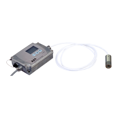
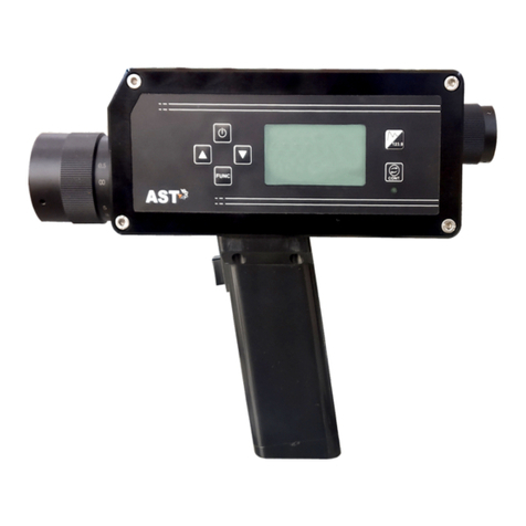
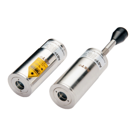
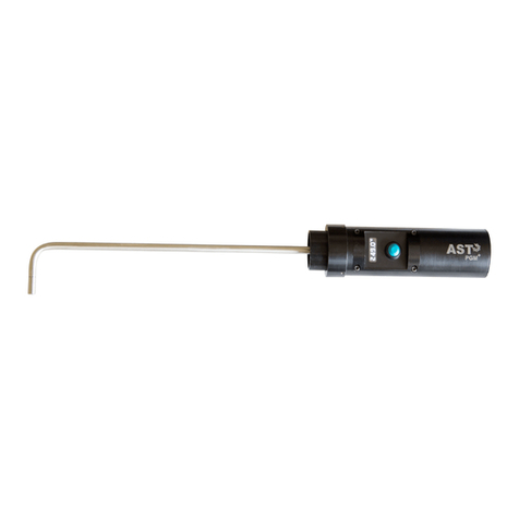
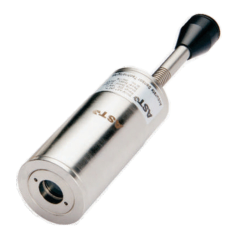
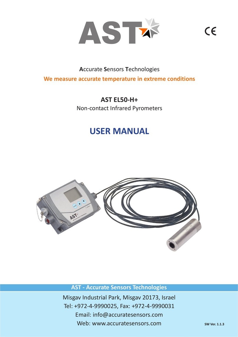
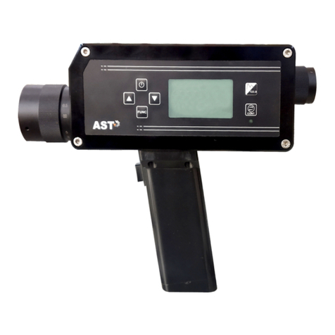
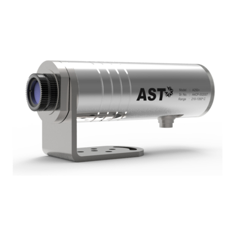
AST 450 G-2 User manual

AST 450 G-2
AST - Accurate Sensors Technologies
Misgav Industrial Park, Misgav 20173, Israel
Tel: +972-4-9990025, Fax: +972-4-9990031
Email: info@accuratesensors.com
Web: www.accuratesensors.com SW Ver. 1.1.3
USER MANUAL
Accurate Sensors Technologies
Non-contact Infrared Pyrometers
We measure accurate temperature in extreme conditions
AST

Accurate Sensors Technologies
AST
Index
1. Chapter - 1
General information
2. Chapter - 2 ....................................................................................................................... 2
Introduction
2.1 Special features of AST 450 G-2
2.2 Application, range and working principle
2.3 Technical specification
2.4 Optics
2.5 Fiber optics
3. Chapter - 3 ....................................................................................................................... 5
Installation of pyrometer
3.1 Control and interface connection
3.2 Emissivity
3.2.1 Example te set emissivity on signal processor
3.2.2 Output test
4. Chapter - 4 ....................................................................................................................... 7
Installation of pyrometer
4.1 Location selection
4.2 Ambient temperature
4.3 Atmospheric condition
4.4 Correct positioning of the pryometer
4.5 Mechanical installation and accessories
4.5.1 Air purge unit
4.6 Electrical installation
4.2.1 Connector pin assignment on the back of the pyrometer
4.2.2 Connection of display device
5. Chapter - 5 ....................................................................................................................... 11
Software installation
5.1 Installation
5.2 Parameters in main screen
5.2.1 COM port address
5.2.1 Pyrometer parameters
5.2.1 Record view
5.2.1 Measurement
6. Chapter - 6 ....................................................................................................................... 15
Calculate Spot size
7. Chapter - 7 ....................................................................................................................... 16
Serial communication protocol
....................................................................................................................... 1

1
Accurate Sensors Technologies
AST
Chapter-1
General Information
We are pleased that you have chosen this high quality and highly efficient AST pyrometer for non-contact
temperature measurement.
Please read this manual carefully, step by step before performing any operation with the Pyrometer. It
contains all the necessary instructions for set up and operation of the pyrometer. When operating the instrument, it
is necessary to follow the general safety instructions. All general information regarding handling, cleaning, and
maintenance of pyrometer are offered according to best of our knowledge & experience.
1.1 Safety Measures
This section provides an overview about important safety regulations.
1.1.1 General
Each person working with the pyrometer must have read the user manual before operation. The Pyrometer
has only to be used for the purpose described in the manual.
1.1.2 Safety Precaution
The Pyrometer works only with a potential-free low voltage of range 24V DC. This voltage is not harmful for
the user.
1.1.3 Maintenance and use of Pyrometer
Pyrometer can be operated by the qualified person who has got instructions from the supervisor. It is strongly
prohibited to do technical modifications of the device without permission of the manufacturer.
1.1.4 Environmental Protection
The lens or its coating may contain harmful materials and hence it should not be disposed of with normal
waste.
1.1.5 Packaging and storage
Always use a shock-proof package for shipment of the pyrometer. It should be sealed to protect it against
humidity. Also protect the lens of the pyrometer with a cover. They should be stored at the temperature ranges from
-20° to +70° C.
1.1.6 Warranty
AST 450 G-2 instruments have a warranty of two years from the invoice date. AST will replace defective parts,
which arises from design errors or manufacturing faults. In case, if pyrometer is opened, disassembled or modified
then the guarantees will loss.
AST does not accept liability for any damage or losses which might occur, including consequential damages
and financial losses, as a result of use of the equipment.
1.1.7 Copyright ©
© All rights reserved. This document may contain proprietary information and shall be respected as a
proprietary document to AST with permission for review and usage given only to the rightful owner of the
equipment with which this document is associated.
2
Accurate Sensors Technologies
AST
Chapter-2
Introduction
AST 450 G-2 are specially designed highly accurate digital pyrometers to provide high performance and low
maintenance of non contact temperature measurement in the glass industry. Sub-range or response time can be
preset ex-works or adjusted through software. This enables the instruments to be adapted to various measuring tasks.
The pyrometers have solid body in aluminum housing which provide high operation safety even in rough industrial
environment.
2.1 Special features of AST 450 G-2
Ÿ Two wire technique
Ÿ Highly accurate 0.3% of measured value
Ÿ Wide temperature range 600…..1800°C
Ÿ Analog output (4-20 mA)
Ÿ Fast response time: 250 msec Adjustable upto10sec.
Ÿ Adjustable emissivity from 0.05 to 1.00.
Ÿ Test current 12mA USB interface for parameter setting.
2.2 Application, Range and Working Principle
AST 450 G-2 is digital pyrometer based on two wire technique provides digital signal processing with simple
connections. Temperature measurement utilizes the fact that objects emit thermal radiation in an amount that directly
corresponds to their own temperature and surface emissivity. The pyrometer sensor detects the amount of infrared
radiation emitted by the measured object (target). This signal is digitally linear zed and converted into standard analog
output signal.
The applications in which AST 450G-2 pyrometers can be used:
ŸLiquid glass
ŸFurnace Crown
ŸFurnace sidewall
ŸFore hearth
ŸFeeder
Additional applications are the measurement of brick works in regenerators and tank. Use of robust fiber optic cable
with instrument makes it suitable for application in an ambient temperature up to 250°C without cooling.

2.3 Technical Specifications
Measured Temperature
Range
Photodetector Type
Emissivity Range
Model AST 450 G-2
600° - 1800°C
Silicon
0.05........1 adjustable via Rotary Switch
Spectral Range 1µm
Response Time
Accuracy
250 msec. Adjustable up to 10sec
± 0.3 % of the measured value or 3°C whichever is greater
Digital Output USB 2.0
Operating humidity Unlimited
Dimensions/Weight
Adjustable Parameters via
Keypad/software
115 mm x 65 mm x 55 mm (L x W x H) / Weight = 0.5 Kg
Response time, temperature sub range
Readable parameters via software Measured temperature, temperature graph, response time,
temperature sub-range
Power 24V DC
Test Current 12mA
Analog Output 4-20mA, Linear, max Load
Spot size 100 : 1; Min. spot 11 mm
Operating temperature Max. 250°C (Optical Head & Fiber Optic)
0°C +70°C (Electronics)
Fiber Optic 5 mtr long multi fiber in SS flexible conduit
3
Accurate Sensors Technologies
AST
Standard Item supplied with AST 450 G-2:-
þSignal Processor Box
þOptical Head G-2
þMulti Fiber FOC (length - 5 m)
þPower supply cable (length - 1.5 m)
þManual
þCertificate of calibration
þSoftware CD
þUSB cable

4
Accurate Sensors Technologies
AST
2.4 Optics
The heat radiation from target object is received by the pyrometer via the lens and is then converted to
an electrical signal. The measured object may be at any distance from the pyrometer. However, the farther the
measured object is from the pyrometer, the larger the area that will be measured by the pyrometer.
The following drawing shows the optical head spot sizes and the focus distances in relation to distance
from the optical head.
2.5 Fiber optic
The infrared radiation is transmitted from the optics to the signal processor by a fiber optics cable. Fiber
& optical head can withstand ambient temperatures up to 250°C .The optical head carry only the objective lens,
the signal processor has radiation detector and signal processing circuit.
The transmission of signal is totally loss free because a reflecting coating is provided at the inner
surface of the optic cable. Standard length of FOC with pyrometer is 5mtr.
Minimum bending radius:
Momentary, localized (max.250°C) : 30mm
Long term (max.250°C) : 50mm
In coiled condition (max.250°C) : 50mm
----------------------------------------------------------------------------------------------------------------------------------------------------------------------------------------------
Spot Size M (mm)
Distance a (mm)
300 600 1000 1500 2000 3000 5000
11 13 16 18 22 27 50

5
Accurate Sensors Technologies
AST
Chapter-3
Setting at the instrument
3.1 Control and interface connection
Emissivity setting switch
Mounting hole
Test
12 mA
Measurement
Test current switch
Serial interface
Mounting hole
The controls are located under the rear cover, segments are provided to set the parameters. The USB port located
near to the rotary set switches is designed for use with an USB cable.
NOTE: The software program serves only as a means of setting the parameters of the signal processor and was not
designed as a controlling mechanism for measurement systems! After set-up is complete, disconnect the PC
adapter cable and close the converter housing.
ATTENTION :
Prior to connecting: When the PC adapter cable is connected, a direct connection between the PC and the pyrometer
is established. However, there is still the possibility that a voltage difference between the PC and
the signal processor exists in this connection, which can impact the 4-20 mA current output of the
pyrometer. This is especially important if the temperature control of your system (i.e. oven or
furnace temperature) is dependent on the output signal from the pyrometer.
3.2 Emissivity
The exact emissivity should be known to measure the accurate temperature of the object. The emissivity is the ratio
between the level of radiation from an object and the level of radiation from a black body at the same temperature.
Different materials have different emissivity ranging from 0.00 to 1.00 (or 0% to 100%).
Material which reflect more radiation have a lower emissivity & if the material is acting like black body then the value
of emissivity will be ε=1.00 means the material absorb all the incoming radiations.
Factory settings:
ε = 1.00 (switch setting: 00)

6
Accurate Sensors Technologies
AST
3.2.1 Example to set emissivity on the signal processor:
Adjust the emissivity ε, by both switches as shown in the example. Emissivity can be adjusted between 0.05 and 1.00
in increments of 0.01.
NOTE: - If emissivity is set to a value below 5% the pyrometer will automatically set emissivity value of 5%.The setting 00
read as ε=1.00 or 100%
3.2.2 Output test
For test purpose the 4 – 20 mA output can be switched to provide a constant 12 mA signal (corresponding to the
middle temperature value of sub measurement range).This provides a known output signal for setting up a controller or
display device.
ε=1.00 or 100% ε=0.65 or 65%
8
7
9
6
0
5
1
4
2
3
8
7
9
6
0
5
1
4
2
3
8
7
9
6
0
5
1
4
2
3
8
7
9
6
0
5
1
4
2
3

7
Accurate Sensors Technologies
AST
Chapter-4
Installation of the Pyrometer
4.1 Location selection
Qualified operating person should do the installation. Location should be good enough from where pyrometer
should get continuous infrared radiation.
4.2 Ambient temperature
The allowed operation temperature for the pyrometer is 0°C to + 70°C at electronic side and 250°C (max) at fiber and
optical head. Therefore ambient temperature must not exceed this temperature range otherwise it may damage the
pyrometer / fiber and optical head.
4.3 Atmospheric conditions
The pyrometer cannot receive the full infrared energy for the measurement if atmospheric conditions like smoke,
dust or steam are present and hence it result in measuring error. An air purge unit can be helpful to avoid contamination
of the lens.
4.4 Correct Positioning of the pyrometer
To avoid measuring errors caused by a too big spot size the pyrometer must be fixed in the correct measuring
distance, so that the object under measurement fills the spot size.
4.5 Mechanical installation and Mechanical accessaries
Signal processor: To fix the signal processor box remove the top cover & mount it with the help of 2 mounting hole
Optical head:
Thread
M16 x 1 mm
SW 22
108 mm
Thread
M16 x 1.5 mm

8
Accurate Sensors Technologies
AST
Connection:
4.5.1 Air purge unit
To protect the lens from contamination of dust, moisture & other suspended particles air purge unit is used. Air
purge with mounting support supply dry & oil-free pressurized air which generates an air stream Shaped like a cone.
Signal
processor box
Input power
supply +24V
Green fiber mark
FOC
Black fiber mark
Optical head
Furnace top
with clamp
(Reference No. : 8100-01)
Air purge with stainless steel Inconel tubes:
200

9
Accurate Sensors Technologies
AST
(Reference No. : 8100-03)
Air purge with mounting flange for furnace top:
(Reference No. : 8100-02)
Air purge unit with 600 mm ceramic sighting tube:

10
Accurate Sensors Technologies
AST
4.6 Electrical
AST 450G-2 are powered by 24 V DC (very well stabilized, ripple max. 50 mV). When connecting the device to the
power supply ensure correct polarity. The device does not need to be warmed up or run in advance and is immediately
ready for use.
4.6.1 Connector pin assignment on the back of connection cable
4.6.2 Connection of display device
AST offers temperature display device with integrated power supplies for two-wire instruments.
The following model is currently available:
AST 9000- 01: With two limit switches
Pin 1
Pin 2
Pin 3
(White)
(Brown)
(Black)
+24 V
Ground
Shield
1
2
3
Binder 3-pin
female connector
AST 450-G2
BOX
Brown
White
4 - 20 mA
+
-
+
-
Temp. Display Unit
( 4- 20 mA )
Power Supply
+24 V, DC

11
Accurate Sensors Technologies
AST
Chapter - 5
Software Installation
The provided AST software offers possibilities to connect three pyrometers simultaneously for parameter
setting, view real time graph, offline graph and to evaluate measuring data.
5.1 Installation
Install the pyrometer software using the installation guide file on CD ROM. After installation of the software;
Double click the application. It will open the main screen of software.
(Main screen)
5.2 Parameters in main screen
5.2.1 COM Port, Address:

12
Accurate Sensors Technologies
AST
Communication between the AST pyrometer and the software is implemented via a cable connected between
the pyrometer and the PC serial port. This enables the acquisition and recording of data, as well as the transfer of
commands from the software application to the AST pyrometer.
When user select this option then a new box will open where user has to select correct COM Port address where
pyrometer is connected (Example: COM2 in above fig.). Also user has to select address to the pyrometer
(Example: Default 01/printed on the pyrometer sticker). Then click on the close button.
For multiple devices connection, first select number of device & then correctly select COM port & address of
devices.
5.2.2 Pyrometer parameters
After selecting the COM port and address, click on the “pyrometer parameter” option, it will display a parameter
screen as shown below.
(A) Measurement - It shows the temperature measured by the pyrometer.
(B) Basic Range - It shows the minimum and maximum range of pyrometer, User cannot change
this range.
Emissivity - The emissivity factor is important in the calculations that determine temperature.
Here, user can’t set the emissivity. To set the emissivity see the topic “3.2
Emissivity” (3.2.1 Example to set emissivity on the signal processor). The
software will display manually set emissivity by user.
(D) Analog Scale - User can change the sub - range of pyrometer. Sub - range must be within the
basic range of pyrometer, the minimum span between higher & lower range is
51. Analog output will be automatically set according to the sub - range.
(C)

13
Accurate Sensors Technologies
AST
(E) Response time - This parameter is use to set the analog response time of pyrometer. It is
adjustable from 250mS to 10 second.
(F) Change sensor type - It shows pyrometer sensor type. User can change sensor type from two
color to single color and vice versa (only applicable with two color pyrometer).
(G) Temperature scale - User can change the measuring unit of temperature from “Centigrade” to
“Fahrenheit” and vice versa.
(H) Pyrometer address - This parameter shows the pyrometer device address, serial number
& SW Data - and software data software version.
5.2.3 Record view
Record view is for continuous data logging .It records the measured temperature, emissivity with current date &
time.
Steps to start data logging:
1. Click on record view option this will open a new dialog box.
2. Click “record control”, this will open “record control” box & click “Save to file” this will ask to give a file
name & then save the file.
3. Now, press “start record” .This will start data logging. If user want to store sample in a particular time
delay then tick on check box & enter time in “Registration time, Sec” then press set. Now the
software will take sample in a particular duration.

14
Accurate Sensors Technologies
AST
5.2.4 Measurement
This screen shows the real temperature, sensor type, model, basic range, internal temp.& picker status of
pyrometer. Internal temperature of pyrometer will show OK for temperature less than 63°C, if temperature exceeds
63°C, its start blinking in red color.

15
Accurate Sensors Technologies
AST
Chapter - 6
Calculate spot size
This option is used to calculate the spot size at installed working distance of the Pyrometer. When you click on
calculate spot size the new window will open.
WD = Manufactured working distance in (mm).
A = It shows the value of lens opening (Aperture in mm)
S = Manufactured spot size of the pyrometer (mm)
User has to enter the value of WD, A, S, of the installed pyrometer. Now, putting the value of “Installed working
distance” it will show the value of “Installed spot size” and vice versa also. For spot size see section 2.4.

16
Accurate Sensors Technologies
AST
Description Address Items Parameters
Emissivity ‘0400' ‘01' Calculated object emissivity multiplied by 1000. Adjustable
between 0.100 to 1.000
Parameter specifies analog and serial output response time.
See table 1.
‘0105' ‘01'Response time (τ)
Upper measurement range limit in °K (read only)‘0100' ‘01'Upper basic range
Lower measurement range limit in °K (read only)‘0101' ‘01'Lower basic range
Upper analog scale value in °K‘0102' ‘01'Upper sub range
Lower analog scale value in °K‘0103' ‘01'Lower sub range
Adjustable between '0001' to '0255'‘0200' ‘01'Station number
Flag is used to instruct PC SW to show temperature
'0000': Centigrade (Default); '0001': Fahrenheit
‘0201' ‘01'Temperature unit
'0000' = Single color; '0001' = Two color
This parameter is useless for single color sensors.
‘0204' ‘01'Sensor mode
Internal temperature inside device case (read only)‘0006' ‘01'Internal temperature
Device model number (read
only)
‘0E00' ‘01' 10 bytes “AST450C “', if less than 10 bytes pad with space at
endbetween 0.100 to 1.000
Firmware version ‘1300' ‘01' Firmware version number of device (read only)
Sensor serial number (read
only)
‘1400' ‘01' 6 bytes in hex, if less than 6 bytes pad with '0' at start. Only
numbers allowed.
Device type (read only) ‘1301' ‘01' '0001': Single color ; '0002': Two color
'0003': Thermopile; '0004': Reserved
Real temperature and
status code (read only)
‘0000' ‘02' Calculated object temperature in °K and status of sensor (As
shown in Appendix A).
First process status code then real temperature.
Chapter - 7
Serial communication protocol-MT500
This protocol is developed to use in the half duplex addressable communication mode. Master device should
periodically issue requests to each Slave device. The request contains an address of polling “Slave” device. Slave
device reply only on the requests issued by Master. Each Slave has its own address to recognize the issued request.
AST sensors always operate as Slave devices. AST sensors always perform delay of 5 ms before sending an answer on
Master request. MT500_AST protocol uses only RD (Batch Read) and WD (Batch Write) commands. Sending other
MT500 protocol commands causes sensor to consider it as error condition and answer with unknown command
reply. Symbols enclosed within apostrophes ('symbol') means ASCII representation of the symbols. String enclosed
with quotation mark (“string”) means ASCII representation of the string (ended by '\0').
Data format is: 8 data bit, 1 stop bit, No parity, baud-rate 19200.

17
Accurate Sensors Technologies
AST
Byte 1 : Always STX (0x02)
Bytes 2, 3 : The Station Number of the device to read from (2 Hex digits)
Bytes 4, 5 : The command to execute (RD)
Bytes 6-9 : This is the starting address to read from. Must be 4 bytes long
Bytes 10, 11 : This is the number of addresses to read. Must be 2 bytes long
Byte 12 : Always ETX (0x03)
Bytes 13, 14 : The checksum is the lowest 8 bits of the sum of bytes 2 through 12
Example : Read two parameters starting from address 0000, from the station number 10 (0AH). This will read
addresses 0000 and 0001.
Checksum is calculated as the lowest 8 bits of the sum of the Hex codes for bytes 2 to 12.
Reply:
The reply length is L = (N * 4) + 8, Where N = the number of requested Items.
If the command is successful, the reply length will be at least 12 bytes. It consists of the STX, followed by four bytes for
each requested item, then the ETX and Checksum.
Reply to above command if address '0000' contains value 1497 and address '0001' contains value 0000.
In the event of an error, the reply is
Checksum is calculated as the lowest 8 bits of the sum of the Hex codes for bytes 2 to 12.
Reply:
The reply length is L = (N * 4) + 8, Where N = the number of requested Items.
If the command is successful, the reply length will be at least 12 bytes. It consists of the STX, followed by four bytes for
each requested item, then the ETX and Checksum.
Byte
1
STX
Bytes
2, 3
Station
Bytes
4, 5
RD
Byte
L-2
ETX
Bytes
6-9
Data 1
Bytes
10-13
Data N
Byte
L-1, L
Checksum
Byte 1
NAK
0x15
Byte 2, 3
0A
0x30, 0x41
Byte 4, 5
‘R', 'D'
0x52, 0x44
Byte 6
01
0x30, 0x31
Byte 1
STX
0x02
Bytes 2, 3
0A
0x30, 0x41
Bytes 4, 5
RD
0x52, 0x44
Bytes 6-9
0000
0x30, 0x35, 0x39, 0x44
Byte 14, 15
2E
0x32, 0x43,
Byte 12
ETX
0x03
Bytes 10, 11
02
0x30, 0x32
Byte
1
STX
Bytes
2, 3
Station
Bytes
4, 5
RD
Byte
L-2
ETX
Bytes
6-9
Data 1
Bytes
10-13
Data N
Byte
L-1, L
Checksum
Reply to above command if address '0000' contains value 1497 and address '0001' contains value 0000.
Byte 1
STX
0x02
Bytes 2, 3
0A
0x30, 0x41
Bytes 4, 5
RD
0x52, 0x44
Bytes 6-9
059D
0x30, 0x35, 0x39, 0x44
Byte 14, 15
9C
0x39, 0x43,
Bytes 10-13
0000
0x30, 0x30, 0x30, 0x30
Batch Read command:
Byte 1
1 Byte
STX
Bytes 2,3
2 Bytes
Station ID
Bytes 4, 5
2 Bytes
RD
Bytes 6-9
4 Bytes
Address
Bytes 10, 11
2 Bytes
Items
Byte 12
1 Byte
ETX
Bytes 13, 14
2 Bytes
Checksum

18
Accurate Sensors Technologies
AST
In the event of an error, the reply is
Byte
1
STX
Bytes
2, 3
Station ID
Bytes
4, 5
WD
Bytes
6-9
Address
Bytes
10, 11
No. of Items
Bytes
12-15
Data 1
Byte
L-2
ETX
Byte
L-1, L
Checksum
Bytes
(L-6) - (L-3)
Data N
Reply
If the command is successful, the reply is
Byte 1
ACK
0x06
Byte 2, 3
0A
0x30, 0x41
Byte 4, 5
‘W', 'D'
0x57, 0x44
In the event of an error, the reply is
Byte 1
NAK
0x15
Byte 2, 3
0A
0x30, 0x41
Byte 4, 5
‘W', ‘D'
0x57, 0x44
Byte 6
01
0x30, 0x31
Error Codes:
Error Code
‘1'
Description
Invalid check sum
Comments
See how to calculate a check sum
‘5' Illegal Address
number of items in a request is set to 0;
memory segment number in a request is out of 0-25;
Wrong command value, No data at requested address;
‘2' Unknown command Protocol uses only RD (Batch Read) and WD (Batch
Write) commands
‘7' Unsuccessful write It informs Master that it should repeat WD command
‘6' More than 99 items were
requested More than 99 items were requested in command
‘3' Data length error Number of items in WD (Batch Write) command
doesn't match number of data bytes
‘4' ETX not found ETX (0x03) not present in command
Batch Write command:
Byte 1
NAK
0x15
Byte 2, 3
0A
0x30, 0x41
Byte 4, 5
‘R', 'D'
0x52, 0x44
Byte 6
01
0x30, 0x31
0x02
Byte 1
STX
Bytes 2, 3
0A
0x30, 0x41
Bytes 6-9
0400
0x30, 0x34, 0x30, 0x30
Bytes 10, 11
01
0x30, 0x31
Bytes 12-15
03E8
0x30, 0x33, 0x45, 0x38
Bytes 4, 5
WD
0x57, 0x44
Bytes 16
EXT
0x03
Bytes 17, 18
74
0x37, 0x34
Table of contents
Other AST Measuring Instrument manuals
Popular Measuring Instrument manuals by other brands

AEMC instruments
AEMC instruments MN01 user manual

PCB Piezotronics
PCB Piezotronics IMI SENSORS 646B00 Assembly, installation and operating manual

Fluke
Fluke 1587 manual

TESTO
TESTO 816 instruction manual

Tektronix
Tektronix TLA 700 Series Technical reference manual

Honeywell
Honeywell W8600B installation instructions