7
3.2.3 Display Functions
FUNC
1
FUNC
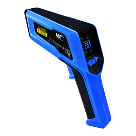
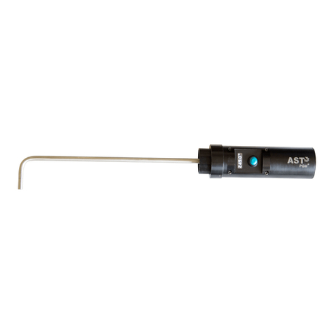
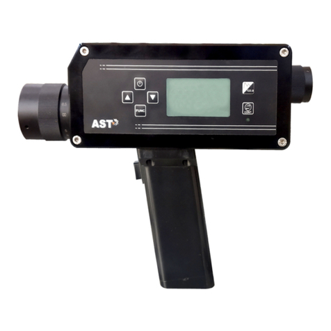
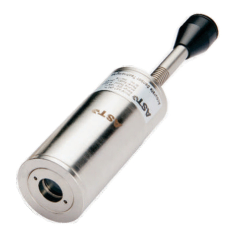
The pyrometer is controlled by adjustment button on left side of instruments.
Function key :- There are different uses of function key first one, this key is use to see different
parameters in device and other one is set the value of parameter which is adjusted by UP &
DOWN key. By pressing of Func Push button brings up the following functions one after other.
They are appears in the bottom left of the LCD display in short form.
Function key adjustable parameters are below.
A) Color Mode: This parameter F) Switch Off Level: The switch
is used to select color modes of level is the function that is
(Single or Two color). used to avoid measurement
errors caused by signals, which
are too low. Although factory default is set to 15%, the
B) Emissivity Ratio: It is the
switch off limit can be adjusted between 1 and 100%.
relationship between the
This function is useful in environment of heavy dust
emissions of a real object and
and obstacles so that pyrometer is able to read in case
the emission of a black Body
of very low energy signals.
radiation source at the same
temperature. For a correct measurement it is
necessary to adjust Emissivity. This parameter can be G) Memory clear :- To clear the
ranges from 0.1 to 1.2. save data from me mory,
memory clear function is used.
By making memory clear
C) Picker :- User can calculate a
function ON, Memory can be cleared.
m a x i m u m “ p e a k ”
temperature value from
specified number store real H) Temperature Unit :- User
temperature in the sensor memory. User can either can select °C or °F unit.
ON or OFF the picker.
(for more details Refer 4.2.2( C))
D) Storage Interval :- Interval I) Set Date & time :- User can
determines whether only one set correct date and time
value will be stored when using this parameter. To get
push button is pressed up-to Access to the menu for date &
the single triggering point. time keep pressing the FUNC button repeatedly.
User can set storage interval from 10ms to 500 Sec.
J) Auto Off :- User can set
E ) R e s p o n s e T i m e : T h e auto off time of pyrometer
response time can be set from from 5mins. to 30mins. In this
20 msec to 10sec when interval mode the pyrometer will
time is OFF. Response time takes automatically off when no key is press in the time of
the value same from Interval Auto Powered OFF. Example if user set 5 minutes in
time when interval is ON and set to specific value. Auto Off then the pyrometer will automatically
Powered OFF if no key is press for 5 minutes.


