www.astsensors.com
Warranty
Workmanship -AST, Inc. pressure transmitters have a limited one-year warranty to the original purchaser. AST, Inc. will replace or repair,
free of charge, any defective transmitter. This warranty does not apply to any units that have been modied; misused, neglected or installed
where the application exceeds published ratings. AST’s sensors are made with pride in New Jersey, USA. If in the area please feel free to
stop by for a visit!
Installation/Applications - The purchaser is responsible for media compatibility, functional adequacy, and correct installation of the transmitter.
AG200 Operating Instructions
Loop Voltage
Select a loop power supply voltage and total loop resistance so that when the loop
current is 20 mA, the gauge will have at least 7.5 VDC at its terminals. Too large
a loop resistance will cause the gauge output to “limit” or saturate before reaching
its full 20 mAoutput.
The minimum loop supply voltage may be calculated from the formula:
Vmin = 7.5V + (20mA x Total loop resistance).
If the loop voltage drops too low, theAG200 will display the LOW LOOP icon. When
the LOW LOOP icon is displayed, all calibration functions, described below, are dis-
abled.
Normal Operation
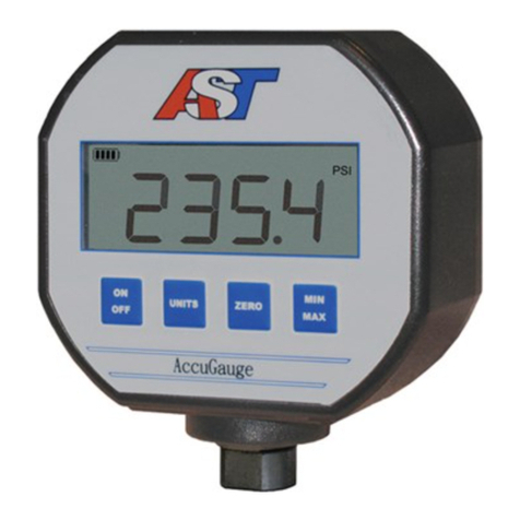
Under normal operation the AG200 displays the pressure in the selected units and
outputs 4mAto 20mAcurrent proportionalto thepressure. TheAG200 outputs 4mAfor
zero or low end pressure, and 20mAfor full scale or high end pressure. If the pressure
reading goes outside the specied range, the AG200 will output as low as 3.5mA or as
high as 24mAloop current.
Press the UNITS button the change the displayed units. The AG200 displays PSI,
bar, Atm, Kg/cm2, InHg, InH2O and mA loop current. The UNITS button does not
affect the current output.
Generating a Test Current
WhentheTESTbuttonishelddepressed, thedisplay andloop currentare switchedto a
test level. Thistest modewill allowsetup andtesting of thecurrent loopby switchingto
this testlevelwhenever desiredwithouthaving toalterthe systempressure. Tochange
the test output level, press the CALIB button, while the TEST button is depressed.
Each time the CALIB button is pressed, the test level current increases by 2mA.
Zero Pressure Calibration
The gauge port must be open with no pressure or vacuum applied. Press the ZERO
andCALIB buttons together for about3 seconds tozero the unit. Thebuttons can be
released when the gauge shows a zero pressure reading. Note: It is best to perform
this step whenpressure units(notmA)areshownon the display. The zero calibration
is retained after the unit is turned off.
Span Pressure Calibration
Span calibration should only be attempted if the user has access to a pressure
reference of known accuracy. The calibration equipment should be at least four
times the gauge accuracy. Zero calibration must be done before span calibration.
To perform span perform the following steps:
1. Choose the calibration units by using the UNITS button.
2. Hold the CALIB button for about 3 seconds.
3. The display will alternate between CAL and the required calibration pressure. For
instance, if the unit needs to be calibrated at 500 PSI, the display will show:
CAL then 500
4. Connect the unit to a pressure source and apply the pressure indicated on the dis-
play.
5. Press and hold the CALIB button for about 3 seconds to complete the calibration. If
the calibration is successful, the display will show:
Done
If there is an error, the display will show:
Err
An error condition will occur if the user tries to calibrate the unit beyond +/- 10% of the
factory calibration.
• To cancel the calibration at any point during the procedure, press and release the
CALIB button.
• Factory calibration can be restored by entering the calibration state, as described in
step 2, then holding the ZERO button for about 3 seconds. The unit will display:
FAC
to indicate that factory calibration has been restored.
Current Output Calibration
TheAG200 has beensetat thefactory tobe inagreement betweenthedisplayed value
and the 4-20mAloop current. These settings should not normally be
adjusted. If adjustment is necessary, perform the following steps:
1. Choose the mAdisplay units, using the UNITS button.
2. Connect the loop to an accurate current measurement device.
3. Hold the CALIB button for about 3 seconds.
4. The display will alternate between CALand 4.00mA:
CAL then 4.00
the loop current will be set to 4.00mA.
5. Use the TESTbuttonto decreasetheoutputloopcurrent by0.01mA. Use theUNITS
button to increase the output loop. Note that even though the output loop current will
change, the display will not.
6. To accept the calibration at 4.00mA, press and hold the CALIB button for about 3
seconds, until the display changes, as described in step 7. You can also cancel any
changes you made, by pressing and releasing the CALIB button.
7. The display will now alternate between CALand 20.00mA:
CAL then 20.00
the loop current will be set to 20.00mA.
8.Again, use the TEST button to decrease the output loop current by 0.01mA. Use the
UNITSbuttonto increasethe outputloop currentby0.01mA. Note thateven thoughthe
output loop current will change, the display will not.
9. To accept the calibration at 20.00mA, press and hold the CALIB button for about 3
seconds, until the display shows:
DONE
You can also cancel any calibration changes you made, by pressing and releasing the
CALIB button.
Factory calibration of the loop current can be restored by entering the loop current
calibration state, as described in step 3, then holding the ZERO
button for about 3 seconds. The unit will display:
FAC
to indicate that factory calibration has been restored.
