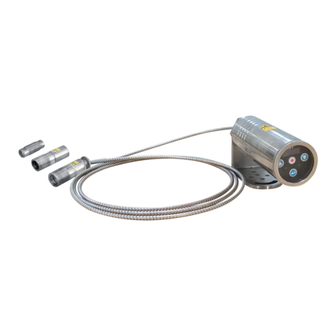
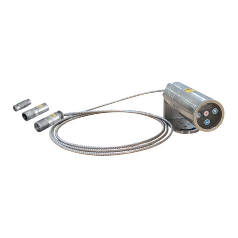
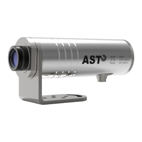
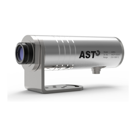
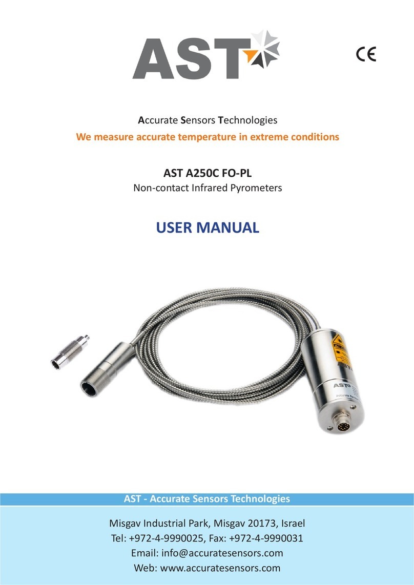
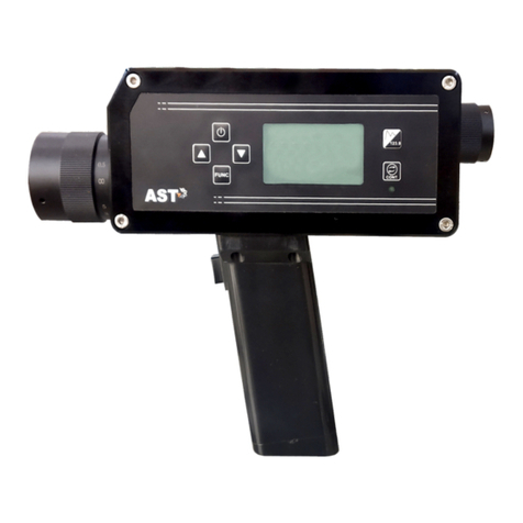
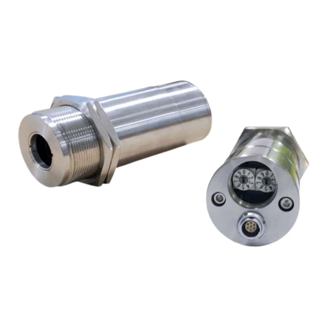
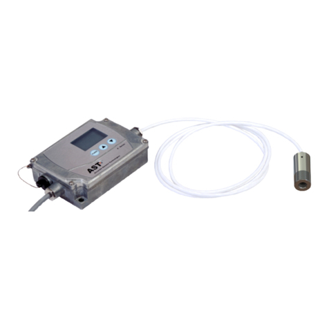
AST A450C FO-PL User manual

AST A450C FO-PL
AST - Accurate Sensors Technologies
Misgav Industrial Park, Misgav 20173, Israel
Tel: +972-4-9990025, Fax: +972-4-9990031
Email: info@accuratesensors.com
Web: www.accuratesensors.com
USER MANUAL
Accurate Sensors Technologies
Non-contact Infrared Pyrometers
We measure accurate temperature in extreme conditions

Index
1. Chapter - 1
General information
2. Chapter - 2 ....................................................................................................................... 2
Introduction
2.1 Application, range and working principle
2.2 Technical specification
2.3 Fiber optic cable
2.4 Optics
3. Chapter - 3 ....................................................................................................................... 5
Installation of pyrometer
3.1 Installation
3.1.1 Location selection
3.1.2 Correct positioning of pyrometer
3.1.3 Mounting of pyrometer
3.1.4 Ambient temperature
3.1.5 Atmospheric condition
3.2 Mechanical accessories
3.3 Electrical installation
3.3.1 Connector pin assignment on the back of the pyrometer
3.3.2 Converter RS-232 ↔ RS-485
3.3.3 Display instrument
3.3.4 Display & parameterizer
4. Chapter - 4 ....................................................................................................................... 11
Software installation
4.1 Installation
4.2 Parameters in main screen
6. Chapter - 5 ....................................................................................................................... 18
Calculate Spot size
7. Chapter - 6 ....................................................................................................................... 19
Serial communication protocol
....................................................................................................................... 1

We are pleased that you have chosen this high quality and highly efficient AST pyrometer for non-contact
temperature measurement.
Please read this manual carefully, step by step before performing any operation with the Pyrometer. It
contains all the necessary instructions for set up and operation of the pyrometer. When operating the instrument, it
is necessary to follow the general safety instructions.
1.1 Safety Measures
This section provides an overview about important safety regulations.
1.1.1 General
Each person working with the pyrometer must have read the user manual before operation. The Pyrometer
has only to be used for the purpose described in the manual.
1.1.2 Safety Precaution
The Pyrometer works only with a potential-free low voltage of range 24V DC. This voltage is not harmful for
the user.
1.1.3 Maintenance and use of Pyrometer
Pyrometer can be operated by the qualified person who has got instructions from the supervisor. It is strongly
prohibited to do technical modifications of the device without permission of the manufacturer.
1.1.4 Environmental Protection
The lens or its coating may contain harmful materials and hence it should not be disposed of with normal
waste.
1.1.5 Packaging and storage
Always use a shock-proof package for shipment of the pyrometer. It should be sealed to protect it against
humidity. Also protect the lens of the pyrometer with a cover. They should be stored at the temperature ranges from
-20° to +70° C.
1.1.6 Warranty
AST A450C FO-PL instruments have a warranty of two years from the invoice date. AST will replace defective
parts, which arises from design errors or manufacturing faults. In case, if pyrometer is opened, disassembled or
modified then the guarantees will loss.
AST does not accept liability for any damage or losses which might occur, including consequential damages and
financial losses, as a result of use of the equipment.
1.1.7 Copyright ©
© All rights reserved. This document may contain proprietary information and shall be respected as a
proprietary document to AST with permission for review and usage given only to the rightful owner of the
equipment with which this document is associated.
Chapter - 1
General Information
1

2
AST A450C FO-PL is specially designed highly accurate digital two color pyrometer with fiber optic to provide high
performance and low maintenance of non contact temperature measurement in demanding industrial environment.
They are designed for areas with high ambient temperature (upto 250°C) without cooling or in areas where strong
electromagnetic interference can influence correct measurement because the fiber & optical head do not contain
any electronic part.
2.1 Application, Range and Working Principle
AST A450C FO-PL is highly accurate two color pyrometer with fiber optics especially designed for rough industrial
environment for temperature measurement of metals, ceramic or graphite. They are suitable for high temperature
measurement ranging from 800°C to 3200°C.
AST A450C FO-PL pyrometers are suitable for industrial purpose due to following advantages:
Ÿ Measurement of temperature is not affected by emissivity of object.
Ÿ Measurement of object temperature is possible where dust, moisture & other contaminants are present in
surrounding environment.
Ÿ The measuring object can be smaller than spot size.
Ÿ The pyrometer can be switched between 1-colour & 2-colour mode.
These pyrometers have solid body in stainless steel housing which provides high operation safety even in rough
industrial environment, and large variety of optics with fixed focus which can be easily used in all industrial areas. The
radiation from hot object is focused on the detector by optics which then travel into mono fiber cable with flexible
stainless steel protection tube and converted into electrical signals. This signal is then linearized and converted into
standard analog & digital outputs.
AST A450C FO-PL has a fast response time of 20msec. Pyrometers have RS-232 or RS-485 outputs. Response
time, emissivity, sub range and peak picker selection can be preset ex works or adjusted through available software.
According to application there are two optical heads small (head 1) & big (head 2).The heat radiation, enter from
optical head, to the lens system & travel through mono glass fiber with flexible stainless steel protection tube where it
is transmitted along to the converted .The optical head contains only the lens system, the electronic are located in the
converter box, so the measurement is possible in atmospheric condition upto 250°C.
Two color pyrometer involves measuring thermal radiance at two different wavelengths and inferring the
temperature from the ratio of these spectral radiance. Radiance ratio thermometers can be significantly more
accurate than single band thermometers in many applications.
The applications in which AST pyrometers can be used are:
ŸInduction heating
ŸAnnealing
ŸWelding
ŸForging
ŸSintering
ŸMelting
ŸRolling mills
ŸRotary kilns
34.50 mm
Ø49.50 mm
Ø48.00 mm
Binder
Connector
SMA 905
¼” x 36
for FOC
AST A450C FO-PL
14.00 mm
Chapter - 2
Introduction
M16 x 1.0
14.50
44
OH-I
25
74.5
25
M25 x 1.5
OH-II

The radiation, from object coming through optical head, is
transported by the lens into the mono fiber cable with flexible stainless
steel protection where it is transmitted to the converter. It can
withstand ambient temperature upto 250°C without cooling because
there is no electronic part.
Length : 2.5m scop of delivery; 5m, 7.5m, 10m,
15m, 30m on request
Ambient temp. : Max 250°C
2.3 Fiber Optics Cable:
(Reference no: 5000-01)
3
2.2 Technical Specifications
Replacement Fibre Optic 2.5mtr
Model AST A450C FO/PL
Measured Temperatures Range
(Analog sub-range adjustable)
Emissivity Range
Emissivity Slope
0.1…..1.0 adjustable
0.75.....1.25 slope adjustable
Spectral Range, µm 0.7.....1.15µm
Photodetector Type Si/Si
Response Time 20msec. Adjustable upto 10S
Accuracy +/-0.5% of the measured value + 1°C
Analog Output 4.....20mA or 0 - 20mA or 0 - 10 V User Selectable
Digital Output USB 2.0, RS-232 / RS-485(Isolated) (User Selectable)
Power 24 V DC
Operating temperature range at fiber Max.250°C at fiber optics cable,0….70°C at pyrometer
end
Fiber Optic 2.5 meter standard (available 5, 10, 15 meter on request)
Sighting Laser pilot light
Isolation Power supply and digital output and analog output are
galvanically isolated against each other
Operating humidity Unlimited
Housing Stainless steel, IP65
Ø49.5mm; L=118mm;/0.6kg
Adjustable Parameters via software Emissivity, Emissivity slope, Analog output, Response
time, Peak picker, Average, Temperature sub range,
Switches between two color & single color
800 °C - 2500 °C & 1000 °C - 3200 °C
Repeatability 0.1 % of reading in °C +1°C

2.4 Optics
Pyrometer receives heat radiation from the measured object, which is converted to an electrical signal after
passing through the lens. The measured object can be at any distance from pyrometer however as far as the
object from pyrometer the measured area (Spot size) will be larger.
Depending on the application the instrument will be delivered with a small or big optical head:
Type I – “Optical head-I” is suitable for use in confined spaces due to very small dimensions. The optics is
adjusted to one of the measuring distances mentioned in following table.
Type II – This optical head is fixed adjusted optical head and is bigger in size than “optical head-I”
Standard Specification of Optical Head:-
4
Variable Optics
Working Distance (mm)
Optical Head Length L (mm)
Optical Pullout P(mm)
Spot Size(mm)
AST A450C FO PL
800 - 2500°C
1000 - 3200°C
Optical Head - ll - V (Variable)
0
66.4
0
18
250
78.9
12.5
1.3
300
75.75
9.35
1.5
400
72.8
6.4
2
600
70.1
3.7
3
800
68.8
2.4
4
1000
68.1
1.7
5
1500
67.15
0.75
7.5
2000
66.7
0.3
10
2500
66.4
0
13
18 1.3 1.5 2 3 4 5 7.5 10 13
User can easily find out the spot size For example, if
factory made working distance is 260mm & pyrometer is AST
250 FO-PL then spot size is 6.5mm for head-I (as given in above
table). If user installed this pyrometer at 700mm then spot size
is not 17.5mm (as given in table), user should have to calculate
as given below method.
Case-I: If installed working distance is greater than manufactured working distance
Case-II: If installed working distance is smaller than manufactured working distance
SS 5.0 mm
68.1
1.7 WD 1000 mm
Pull Out (P) = 1.7 mm
Optical Head Length (L) = 68.1 mm
Example of OH(ll) - V
Optical Head
Optical Head - I
Spot Size(mm)
120
260
700
90
200
600
4500
Working
Distance (mm)
800°C - 2500°C 1000°C - 3200°C
Spot Size(mm)
1.2
2.6
7
0.5
1
3
24
1.2
2.6
7
0.5
1
3
24

Chapter - 3
Installation of the Pyrometer
3.1 Installation
3.1.1 Location selection
Qualified operating personnel should do the installation. Location should be good enough so that pyrometer
should get continuous infrared radiation.
Pyrometer distance from object is according to below points:-
1. Pyrometer spot size should be small than object size.
2. Know your pyrometer spot size according to point 2.3.
3. Pyrometer ambient temperature should be within 0° to 70°C (read 3.1.4).
3.1.2 Correct Positioning of the pyrometer
With pilot light (PL)
A laser targeting light will help to correct the position of the pyrometer. It is recommended that laser should be
switched off while measurement. It will increase the life of laser. To avoid measuring errors caused by a too big spot
size the pyrometer must be fixed in the correct measuring distance, so that the object under measurement fills the
spot size.
Note: The laser spot (PL) is only for indication of measuring spot, not exactly shows the measuring area.
Due to fiber optic cable the pyrometer can be placed remote from high temperature area. The optical head
containing sensor is placed at the object whose temperature is to be measured. The radiation from hot object is
focused on the detector by optics which then travel into mono fiber cable with flexible stainless steel protection tube
and converted into electrical signals. This signal is then linearized and converted into standard analog & digital
outputs.
3.1.3 Mounting of pyrometer
To install the sensor head at the place of measurement a mounting support is supplied as an accessory, after
losing the clamp screws, it can be fastened correctly.
3.1.4 Ambient temperature
The allowed operation temperature for the pyrometer is 0°C to +70°C. But the temperature at fiber optic &
optical head is 250°C max. Therefore, if sensor head is to be used above 250°C water cooling jacket with built in air
purge unit is used otherwise it may damage the pyrometer. The ambient temperature is dependent on the
temperature and flow rate of cooling water. Details of air purge & water cooling jacket is given in point 3.2.
3.1.5 Atmospheric conditions
The pyrometer cannot receive the full infrared energy for the measurement if atmospheric conditions like
smoke, dust or steam are present and hence it result in measuring error. An air purge unit can be helpful to avoid
contamination such as dust and humidity on the lens. The air supplied should be at normal temperature with oil &
moisture free. The air purge generates an air stream shaped like a cone and blows particles from the lens area.
5

6
Water Cooling Jacket Incl. Air Purge Unit- Optical Head-II
(Reference No: 8000-01)
Adjustable Mounting for Optical Head-II
(Reference no: 8200-03)
Air Purge Unit-Optical Head-II
(Reference No: 8200-01)
3.2 Mechanical accessories
Water pressure : < 10 bar
Air pressure : < 0.5 bar
Air consumption : 2...3 m³/h
Ambient temperature : < 200°C
Metal : Stainless steel
Weight : 1.35 Kg
Ø50
Ø48
31
50
138.50
FOR 6 mm INSIDE
DIAMETER HOSE
Ø30
25
3 x M5
55
100
50
25
3
27
76
Ø25
Ø38
for 6 mm inside
diameter hose

3.3. Electrical Accessories
Power Supply Unit
(Reference no: 9000-02)
AST A450C FO-PL is powered by 24V DC (well stabilized
ripple max 50mV).The input power supply is 110/230v AC check
the polarity before connecting the device
3.3.1 Connector Pin Assignment On The Back of The Pyrometer
RS-232 Connection
7
12-Core Cable
(Reference no: 7002-02)
Adjustable Mounting for Optical Head-I
(Reference No: 8200-04)
35
18
22
29
2
Air Purge Unit for Optical Head-I
(Reference No: 8200-02)
for 3 mm inside
diameter hose
25
47

8
3.3.2
When pyrometer is connected to USB 2.0 cable, it is powered through USB 2.0. At this stage only USB 2.0
output is provided. For Analog output and Laser to work DC supply (+24V DC) must given to pyrometer.
While USB 2.0 is connected RS-232 / RS-485 communication is not possible. LED light indicates USB 2.0
operation.
USB 2.0 Connection:
12-pin Binder connector RS-232 communication connection
Male
Female
L
C
BA
J
K
G
H
M
F
E
D
LC
J
B
A
K
G
H
M
FE
D
D - Type 9 pin Female
Connector
LC
J
B
A
K
G
H
M
FE
D8
3
7
2
4
9
6
1
5
RxD
DGND
TxD
H
Pin
A
G
C
D
F
H
M
J
K
B
Colour
Red
White
Blue
Pink
Black
Yellow
Violet
Brown
Green
Yellow
Grey
Indication
+ 24 V DC In
Ground
TxD (RS-232) / D- (RS-485)
RxD (RS-232) / D+ (RS-485)
RS-232 communication
(-) 4-20mA / 0-20mA
(+) 4-20mA / 0-20mA
Short / Open both wires for laser
ON/OFF
- (0-10V)
+ (0-10V)
Used for
Power supply
RS-232/ communicationRS-485
Analog current output
Laser ON/OFF
Analog voltage output
E Blue-Yellow N/A
L Red-Grey N/A
Not used
Open screw for USB 2.0
LED Light

9
Power ON Pyrometer:
1. Connect the 12-core cable (Supplied with pyrometer) with pyrometer 12-pin binder connector given at the
back side of pyrometer.
2. Connect the 12-core cable supply wire with +24V DC as given in table above.
3. Connect remaining wires as per your requirement (details given in table above).
4. Provide insulation for not used end points of 12-core cable.
5. Now, the pyrometer can be switch ON.
3.3.2 Converter RS-232 ↔ RS-485 :
The pyrometer can communicate with PC using RS-232 or RS-485.
RS-232 is used only for short distances.
RS-485 is well suited for long distance transmission. Standard on PC
is RS-232, so a converter is used which converts RS-485 to RS-232.
Converter RS-232 ↔ RS-485
9000-03)(Reference no:
RS-485 to RS-232 Connection
RS-232 to RS-485 to RS-232 Connection

10
3.3.3 Display Instrument
Temperature Indicator
(Reference no: 9000-01)
Display & Parameterizer
P-120
(Reference no: 9001-01)
3.3.4 Display & Parameterizer
To display the measured temperature 7 segment digital
indicator is used. Device has following specifications:
Power supply I/P : 85 to 265 V, AC/DC
Analog I/P : 4….20 mA
Retransmission : 4….20 mA
Power supply O/P : 24V, DC
Display : 4 Digits
Alarm : 2
AST P-120 is a high precision LED indicator for non contact
temperature measurement. With indication of measured
temperature user can easily parameterize a connected AST digital
pyrometer without any PC.
Device has following specification:
Power supply : 100 – 240V, AC or 24V, DC
DC analog O/P : 0-20 mA or 4-20 mA
Digital interface : RS-232 or RS-485
Pilot light : Pilot light On/Off with keys
Multi-Pyrometer Connection

Chapter - 4
Software Installation
The provided AST software offers possibilities to connect three pyrometers simultaneously for parameter
setting, view real time graph, offline graph and to evaluate measuring data.
4.1 Installation
Install the pyrometer software using the installation guide file on CD ROM.After installation of the software;
Double click the application. It will open the screen of software.
4.2 Parameters in main screen
4.2.1 Communication
Communication between the AST pyrometer and the
software is implemented via a cable connected between
the pyrometer and the PC serial port. This enables the
acquisition and recording of data, as well as the transfer of
commands from the software application to the AST
pyrometer. Communication can be done by clicking on
“Communication panel" and select correct COM Port
address where pyrometer is connected. Also user has to
select address of the pyrometer(Example: Default 01/
printed on the pyrometer sticker). Then click on CONNECT
Button.
11

12
(A)Emissivity settings The emissivity can be set by
clicking on "Parameters” and select or type in the desired
emissivity directly in the description field. The emissivity
value will be transferred to pyrometer by hitting the "TAB
" button.
(B)Response time The desired response time can be
chosen in the panel Parameter by clicking the
appropriate list box. This parameter is use to set the
analog response time of pyrometer.
(C)Sub Range User can change the sub range of
pyrometer in the panel Parameter. Sub range must be
within the basic range of pyrometer, the minimum span
between higher & lower range is 51. Analog output will
be automatically set according to the sub-range by
hitting "TAB" button.
(D)Sensor Type It shows pyrometer sensor type. User
can change sensor type from two color to single color
and vice versa (only applicable with two color
pyrometer).
Temperature
It shows the temperature measured by the pyrometer
PARAMETER SETTINGS
All user selectable device parameters can be set by using the software in the Panel "Parameter"
For communication of multiple pyrometers, select different com port and address.

13
(E)Switch off level% ( for two color pyrometer) The switch of level is the function that is used to avoid measurement
errors caused by signals, which are too low. Although factory default is set to 15 %, the switch off limit can be adjusted
between 2 and 50%.
(F)Unit User can change the measuring unit of temperature from “Centigrade" to “Fahrenheit" and vice versa.
(G)Clear time (tCL) If the peak picker is switched on, the highest last temperature value will always be displayed and
stored. As such, it may be beneficial to periodically clear and reset the stored values in order to obtain new
temperature readings.
This feature is particularly useful when object temperature is not uniform across its dimension or the pyrometer is not
constantly viewing an object to be measured. The peak picker works on two buffer memory to find maximum value
over a defined interval. With the first memory, the highest measured value is held and is deleted alternately in the
time interval set (clear time). The other memory retains the maximum value throughout the next time interval. The
disadvantages of fluctuations in the display with the clock frequency are thereby eliminated.
Note:
The maximum value storage coincides with adjustments made to response time. Therefore:
(I) Clear time<= the adjusted response time is useless
(ii) Clear times must be at least 5 times longer than the response time.
(iii) Only maxima with full maximum value can be recorded, which appear at least 5 times longer than response time.
The following setting are possible :
OFF : At clear time “OFF” the maximum value storage is switched off and only momentary values are measured.
10msec...25sec : Any clear time between 10msec and 25sec(please refer to Note(ii) above) when set, estimates the
maximum values and holds it in two buffer memory. After the entered time, the storage will be deleted.
Auto : “Auto” mode is used for discontinuous measuring task, such as object being transported on a conveyer belt in
such a case the maximum value for each object has to be indicated. when the object passes the measuring beam of
the pyrometer, the maximum value is stored until a new hot object appears in the measuring beam. The temperature
which has to be recognized as “hot” is defined by the low limit of the adjusted sub range. The stored maximum value
will be deleted when the temperature of the new hot object exceeds the low limit “from” of the sub range by at least
1°C. If a lower limit is not entered, the maximum value storage will be deleted whenever the low level of the full
measuring has been exceeded.

14
RECORD
Record is for continuous data logging. It records the measured temperature, emissivity with current date & time.To
start data logging click on start button. If user wants to record emissivity, click on record emissivity button. After
Clicking Start button window appears where user can specify the file name & location.
This screen shows the Model, basic range,serial number,version, Head temperature, internal temperature, working
distance, spot size-apperture.
(H)Relative energy(for two color pyrometer) The relative energy shows a signal weakening which can be caused by
contaminations of the optics or a viewing window or by dust in the field of view or a too small measuring object.
Relative energy shows the measured intensity compared to the intensity, a black body radiation source would have at
a determined ratio temperature of the pyrometer.
(I)Analog Range User can select the analog range from the option 4-20mA, 0-20 mA & 0-10V.
(J)Comm. Mode User can select the communication mode as per requirement [RS-232 / RS-485].
Note: For connection diagram from RS-232 to RS-485 & RS-485 to RS-232 Refer Page No:-9
To view parameters of multiple devices select the pyrometer name from the drop down list that appears at the top of
the screen.
Device information
Pyrometer specific information will be displayed in the Info Panel

15
If user wants file in Spreadsheet format, user can export by choosing Excel Spreadsheet in file menu.
To record emissivity, click on Record Emissivity button.
Record will be saved as .txt format.

16
To see previous record open the file by clicking on menu File open.
Screen containing historical trend & historical data will appear.
File will be stored in .xls format named as “export”.

17
NOTE:
After connecting the pyrometer right click on the graph screen and choose "Set to default" option from pop-up menu.
Temperature graph of connected pyrometer is displayed on right side of the screen. This shows the measured
temperature corresponding to the time.

Chapter - 5
Calculate Spot Size
To calculate Spot Size click on Utility
This option is used to calculate the spot size at installed working distance of the Pyrometer. When you click on
calculate spot size the new window will open.
Calculate Spot Size
WD = Manufactured working distance in (mm).
A = It shows the value of lens opening (Aperture in mm)
S = Manufactured spot size of the pyrometer (mm)
User has to enter the value of WD, A, S, of the installed pyrometer (These values are given in section – 2.3). Now,
putting the value of “Installed working distance” it will show the value of “Installed spot size”.
18
Table of contents
Other AST Measuring Instrument manuals
Popular Measuring Instrument manuals by other brands

TASKING
TASKING iSYSTEM iC5700 user manual

Andor Technology
Andor Technology HoloSpec quick start guide

ADA INSTRUMENTS
ADA INSTRUMENTS ARMO MINI operating manual

CLA-VAL
CLA-VAL XP2F Installation operation & maintenance

geo-FENNEL
geo-FENNEL A-Digit 50 user manual

Dwyer Instruments
Dwyer Instruments DCG Series Installation and operating instructions