AST A250+ PL/TL/Video User manual

AST A250+/A450+ PL/TL Video
USER MANUAL
Accurate Sensors Technologies
Non-contact Infrared Pyrometers
We measure accurate temperature in extreme conditions
AST - Accurate Sensors Technologies
Misgav Industrial Park
Tel: +972-4-9990025, Fax: +972-4-9990031
Email: info@accuratesensors.com
Web: www.accuratesensors.com
, Misgav 20173, Israel

Index
1. Chapter-1
Generalinformation
2. Chapter-2 ....................................................................................................................... 2
Introduction
2.1 ProductKeyFeatures,ApplicationandRange
2.2 Technicalspecification
2.3 Optics
3. Chapter-3 ....................................................................................................................... 5
Basics&InstallationofPyrometer
3.1 BasicsofInfraredtemperaturemeasurementofanobject
3.2 Installation
3.3 LocationSelection
3.4 MechanicalAccessories
3.5 ElectricalInstallation
4. Chapter-4 ....................................................................................................................... 13
SettingattheInstruments
4.1 Operation
4.2 KeyDescriptions
4.3 AdjustableParameters
4.4 OtherParameters
5. Chapter-5 ....................................................................................................................... 17
Softwareinstallation
4.1 Installation
4.2 Parametersinmainscreen
6. Chapter-6 ....................................................................................................................... 24
Maintenance
7. Chapter-7 ....................................................................................................................... 25
Serialcommunicationprotocol
8. AppendixB ....................................................................................................................... 30
10.AppendixC ....................................................................................................................... 31
....................................................................................................................... 1
Accurate Sensors Technologies

CongratulationsonchoosingthishighqualityandhighlyefficientASTpyrometerfornoncontacttemperature
measurement.
Pleasereadthisusermanualcarefully,stepbystep,includingallnotesofsecurity,operationandmaintenance
beforeinstallingthe pyrometer.This manual containsall thenecessary instructions forsetup andoperationof the
pyrometer.Thissectionprovidesanoverviewaboutimportantsafetyregulations.
SomeImportantSafetyRegulationsGivenBelow
1. SafetyPrecaution
Eachpersonworkingwithpyrometermustreadtheusermanualbeforeoperation.Thepyrometerhasonlyto
be usedforthe purposedescribed inmanual. Thepyrometerworksonly with apotential freelow voltageof range
24VDC.Thisvoltageisnotharmfulforuser.Thepyrometermaycontainharmfulmaterialandhenceitshouldnotbe
disposedofwithnormalwaste.
2. PackagingandStorage
Alwaysuseashockproofpackageforshipmentofpyrometer.Itshouldbesealedtoprotectitagainsthumidity.
Alsoprotectthelensofpyrometerwithcover.Theyshouldbestoredatthetemperaturerangefrom-20°cto70°c.
3. LimitofLiabilityandWarranty
All general information and notes for handling, maintenance and cleaning of this instrument are offered
accordingtothebestofourknowledgeandexperience.
ASTreservestherighttorevisethisdocumentandtomakechangefromtimetotimeinthecontenthereofwithout
obligationtonotifyanypersonorpersonsofsuchrevisionsorchanges
ASTinstrumentshaveawarrantyoftwoyearfromtheinvoicedate.Thiswarrantycoversmanufacturingdefectsand
faultswhichariseduringoperationonlyiftheyarethe resultsofdefectscausedbyAST.
AST does not accept liability for any damages or losses which might occur, including consequential damages and
financiallosses,asaresultofuseoftheinstrument.
4. Copyright
Allrightsreserved.thisdocumentmaycontainproprietaryinformationandshallberespectedasaproprietary
documenttoASTwithpermissionforreviewandusagegivenonlytotherightfulowneroftheinstrumentwithwhich
thisdocumentisassociated.
Chapter - 1
General Information
1
Accurate Sensors Technologies

Chapter - 2
Introduction
AST A250+/A450+ PL/TL/Video are specially designed highly accurate digital pyrometers to provide high
performance and low maintenance of non contact temperature measurement in demanding industrial
environment.
2.1 ApplicationandRange
The AST A250+/A450+ PL/TL/Video pyrometers are especially designed for industrial purposes. They are
suitableforhightemperaturemeasurementrangingfrom210°Cto3000°C.
Thesepyrometershavesolidbodyinstainlesssteelhousing,whichprovideshighoperationsafetyeveninrough
industrialenvironment,andlargevarietyoffocusableopticswhichcanbeeasilyusedinallindustrialareas.
These pyrometers have OLED display which shows temperature and provides menu selection via
parameterizaion keys. AST A250+/A450+ PL/TL/Video have fast response time of 2msec. The RS-485 for long
distance communication between pyrometer & PC software Infrasoft. Response time, emissivity, sub-range and
peakpickerselectioncanbepresetex-worksoradjustablethroughavailablesoftware.
The pyrometer temperature measurement method utilizes the fact that objects emit thermal radiation in an
amountthatdirectlycorrespondstotheirowntemperatureandsurfaceemissivity.
The pyrometer sensor detects the amount of infrared radiation emitted by the measured object (target). The
infrared signal is analyzed and the temperature it represents is analyzed by built-in microprocessor. AST
A250+/A450+PL/TL/Videoworkin4-wiretechnology.
TheapplicationsinwhichASTpyrometerscanbeusedare
üPreheating
üAnnealing
üTempering
üWelding
üForging
üHardening
üMelting
üSintering
üSoldering
üRolling
üBrazing
üNormalizing
ProductKeyFeatures,
StandardItemsuppliedwithASTA250+/A450+PL/TL/Video
üASTpyrometer
üConnectioncable12-core(length-5m)
üASTsoftwareCD
üManual
üCertificateofcalibration
Accurate Sensors Technologies
2

2.2 Technical Specifications
Model A250+ PL/TL/Video A450+ PL/TL/Video
Temperature Range
(Analog sub-range adjustable)
Spectral Range
Photodetector Type
Distance to Spot Size Ratio
Emissivity (ε)
Response Time
Accuracy
Repeatability
Sighting Options
Analog Output
Digital Output
Operating Temp. Range
Storage Temp. Range
Adjustable Parameters and Features via Software/
Keypad
210°C….1350°C
250°C….1800°C
300°C....2500°C
350°C....3000°C
1.6 µm
InGaAs
75:1 (210°C….1350°C)
150:1 (250°C….1800°C)
300:1 (300°C….2500°C)
300:1 (350°C.... 3000°C)
0.1….1.0 adjustable
2 msec adjustable upto 10 sec
± 0.3% of the measured value + 1°C
0.1% of reading in °C + 1°C
Laser Pilot Light (PL) / ThroughThe Lens (TL) / Video output
RS-485 (Isolated)
0°C…….70°C
0°C…..200°C (With water cooling jacket)
-20°C…70°C
Emissivity, Response Time, ClearTime(Peak Picker),Analog Output, Analog Scale (Sub Range),
Unit Of Temperature(°C/°F), Record feature, Match Temperature etc.
600°C….2500°C
1.0 µm
Si
300:1 (600°C….2500°C)
0-20mA, 4-20mA(User selectable)
Power Supply
Power Consumption
Laser Power
Protection Class
Housing
Isolation
Operating Humidity
Weight & Dimensions
12V to 28V DC with reverse voltage protection
Max 2.5 watt - PL/TLmodels
Max 3.5 watt - Video models
<1 m watt (Only PLModel)
IP65
Stainless Steel
Power supply, Digital output andAnalog output are galvanically islolated against each other
10-95%, Non-Condensing Conditions
1200g
Dia= Ø56 mm; Length=185.5mm
Dimensions
Fig. 1 Dimensions of Pyrometers
Accurate Sensors Technologies
3
Relay Output Relay output with hysteresis 60V DC / 42VAC RMS, 0.4A
Model A450C+ PL/TL/Video
Pixles
Video Format
Video Output
Impedance
Image Sensor
MaximumAnalog Video Cable Run
Cable Connection Type
Operating Temperature
1/4 " CMOS
Upto 40m Special Co-axial Cable Used
BNC
0°C ..... 65°C
640 x 480
PAL
CVBS
75R
2.3 Video Specifications

475 6.40 3.20 1.60
Spot Sizes(mm)
Focused working distances
WD (mm)
500
700
800
1000
1500
2000
3000
5000
A250+
210°C - 1350°C
(75:1)
6.70
9.40
10.70
13.40
20.00
26.70
40.00
66.70
A250+
300°C - 2500°C
350°C - 3000°C
(300:1)
3.40
4.70
5.40
6.70
10.00
13.40
20.00
33.40
A450+
600°C - 2500°C
(300:1)
1.70
2.40
2.70
3.40
5.00
6.70
10.00
16.70
2.3 Optics
measured. This heat radiation is passed through the lens sensor and then converted to an electrical signal. The
fartherthemeasuredobjectfromthepyrometer,thelargertheareathatwillbemeasured.
Table1:Somefixedopticsfocusisasbelow
Thepyrometermeasuretemperaturebyreceivingheatradiationfromtheobjectwhosetemperaturehastobe
Accurate Sensors Technologies
4
Adjustingtherequiredmeasuringdistance:-
To achieve the spot sizes mention in the table above required
measuring distance must be adjusted. This can be done between the
smallest and the biggest limit value. For releasing the optics has to be
turned anti clock wise. Then it can be pushed or pulled to find the
correctmeasuringdistance.Forfixingtheopticshastobeturned clock
wise.
Adjustingthemeasuringdistancewiththehelpofthetable:-
The table mentions the minimum and maximum measuring
distance for each optics as well as serval other values. The length “L”
canwemeasuredwithacaliper.Thislength"L"canreachmax.upto14
mm.
Adjusting the measuring distance with help of the thru lens view
finder:-
The focusable optics is correctly adjusted to the required
distance,ifthemeasuringobjectisshown as a sharp image in the view
finder.Acirclemarksthepositionofthemeasuringspot.
Adjusting the measuring distance with help of the laser targeting
light:-
On the focused measuring distance the laser has a smallest spot
size. length “L”
Unlock
Anticlockwise
Lock
Clockwise
Length
LLength
L
9000 120.00 60.00 30.00
14.00
13.20
8.70
7.40
5.70
3.50
2.40
1.40
0.50
0
13.60
12.70
8.50
7.20
5.50
3.40
2.30
1.30
0.50
0
Fig. 2 Adjusting Measuring Distance
A250+
250°C - 1800°C
(150:1)
1.60
1.70
2.40
2.70
3.40
5.00
6.70
10.00
16.70
30.00

Chapter - 3
Basics & Installation of the Pyrometer
3.1 Infraredtemperaturemeasurementofanobject
Each and every object emit definite amount of infrared radiation and its intensity varies according to the
temperatureofobject.Wavelengthofinfraredradiationliesapproximatelybetween0.7to14µmdependingonthe
material and properties of object. Infrared radiations are sometimes also referred to as “heat radiations” depends
mostlyon thematerial.This materialdependent constantvalueisknown as“emissivity”,havealookat appendixB
foremissivityvalues.
3.1.1 Emissivity(?)
Emissivityis theratioof energyradiatedfroman objectto theexteriorandenergyradiatedfrom blackbody.
Theemissivityvarieswiththesurfaceconditionoftheobjectandalsowithtemperaturevariationandwavelength.If
this value is not accurate, then the true temperature cannot be measured. In other words a variation or change in
emissivitywillcauseachangeinthemeasurement.
If the value of emissivity low, your measured results may contain some errors due to interfering infrared
radiationsformobjects whicharebehindthe targetobjectlikeheatingsystems,fireclaybrisketc.Usuallysuch type
ofproblemsoccurswhilemeasuringverythinmaterialslikeglass,plasticetcorsomereflectingsurface.
This error can be reduced if the sensor is shielded from reflecting radiation sources and also by properly, carefully
installingthedevice.
BytheapplicationofKirchhoff'slawofthermalradiation“atthermalequilibrium,theemissivityofthebodyis
equaltoitsabsorptivity(α)”.Soforperfectblackbody,?is1whileanyrealobjectwouldhave? lessthan1.Alsothe
transmissivity(т)andreflectivity(ρ)iszero.Thesumofabsorptivity,reflectivityandtransmissivityisalways1.
α + ρ + т= 1
Byemissivityfactormaterialscanbecategorizedas
üMetals
üNonmetals
üTransparentmaterials
3.1.2 Calculationofemissivityoftargetobject
Therearevariousmethodstodo sobutoneofmostprominentlyusedisCalculatetheactualtemperatureof
targetobjectusingaRTD,Thermocoupleetc.Measuretheobject'stemperaturebypyrometerandadjustemissivity
settings in pyrometer unless correct temperature value is reached. Hence correct emissivity is measured of the
targetobject.
3.2 Installation
3.2.1 Mechanicalinstallationofpyrometer
Afterallpreparationsarecompletedyoucaninstallpyrometer.Installationofpyrometerdependsonthetype
ofbracketyouareusingandthetypeofsurface.
Basicsof
Accurate Sensors Technologies
5

3.2.3 ViewingAngles
Thepyrometercanbeplacedatanyanglefromthetargetobjectupto30°.indicatedinthebelowdiagram.
Fig.3 Proper mounting of pyrometer
Fig. 4 Pyrometer Acceptable Viewing angles
Background
Best
critical
Incorrect
Pyrometer
Target greater than
spot size
Target equal to
spot size
Target smaller
than spot size
Acceptable
Angles
Pyrometer
Best
90°C to target
Good
30°C to 90°C target
Bad
0°C to 30°C target
Accurate Sensors Technologies
6
3.2.2 Distanceofpyrometerfromobject
Thedesiredspotsizeon thetargetwill determinethemaximummeasurementdistanceandthefocallength
of the optical module. To avoid wrong readings the spot size of target must contain entire field view of the
pyrometer.Thepyrometermustbemountedsotheentirefieldofviewisthesameorsmallerthanthedesiredtarget
size.Thisisindicatedinthebelowdiagram.

3.3 Locationselection
Qualified operating person should do the installation. Location should be good enough so that pyrometer
shouldgetcontinuousinfraredradiation.
Pyrometerdistancefromobjectisaccordingtobelowpoints:-
1. Pyrometerspotsizeshouldbesmallthanobjectsize.(read3.2.2&3.2.3)
2. Knowyourpyrometerspotsizeaccordingtopoint2.3.
3. Pyrometerambienttemperatureshouldbewithin0°to70°C(read3.3.3).
3.3.1 CorrectPositioningofthepyrometer
Withpilotlight(PL)
Alaser targetinglightwillhelptocorrectthe positionofthepyrometer.Itis recommendedthatlasershould
be switched offwhile measurement. Itwill increasethe life oflaser.To avoidmeasuring errors caused bya too big
spotsizethepyrometermustbefixedinthecorrectmeasuringdistance,sothattheobjectundermeasurementfills
thespotsize.
Withthroughthelenssighting(TL)
In case of through the lens sighting a reticule circle marks the position of the measuring spot. This circle is
true-sidedandparallax-free.
WithcompositeVideooutput
Incaseof videooutputareticlecircleonthecenterof cameraviewmarksthepositioningof themeasuring
spot.Thecameraviewshowsrealtemperatureofthetargetandreticleonthecenteroftheview.
Note:Thelaserspot(PL)/reticulecircle(TL)isonlyforindicationofmeasuringspot,notexactlyshowsthemeasuring
area.
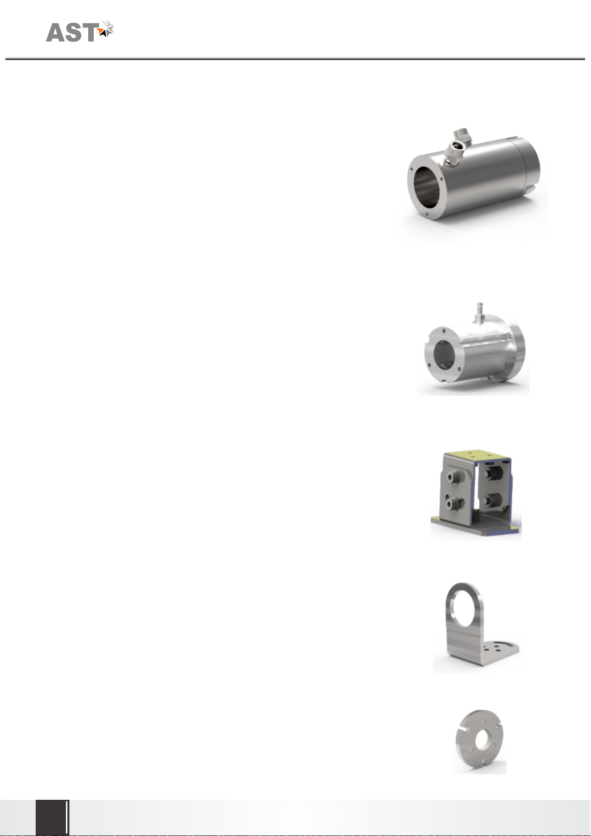
3.3.2 Mountingofpyrometer
To install the pyrometer at the place of measurement a mounting support is supplied as an accessory, after
losingtheclampscrews,pyrometercanbemountedcorrectlyinthemountingclamp.
3.3.3 Ambienttemperature
The allowed operation temperature for the pyrometer is 0°C to 70°C. Therefore if pyrometer is to be used
above 70°C upto 200°C water cooling jacket with built in air purge unit is used otherwise it may damage the
pyrometer. The ambient temperature is dependent on the temperature and flow rate of cooling water. Details of
watercoolingjacket&airpurgearegiveninpoint3.4.1.
3.3.4 Atmosphericconditions
The pyrometer cannot receive the full infrared energy for the measurement if atmospheric conditions like
smoke, dust or steam are present and hence it result in measuring error. An air purge unit can be helpful to avoid
contaminationsuch as dust andhumidity on thelens. Theair supplied shouldbe atnormal temperature withoil &
moisturefree.Theairpurgegeneratesanairstreamshapedlikeaconeandblowsparticlesfromthelensarea.
Accurate Sensors Technologies
7

Fig. 6
(Reference no: 8500-05)
Air Purge Unit
ŸAirpressure : <0.5bar
ŸAirconsumption : 2...3m³/h
ŸMetal : Aluminium
ŸWeight : 0.5Kg
ŸDry,cleanair(Oilanddustfree)
3.4 Mechanical Accessories
ŸWaterpressure : <10bar
ŸAirpressure : <0.5bar
ŸAirconsumption : 2...3m³/h
ŸAmbienttemperature : <200°C
ŸMetal : Stainlesssteel
ŸWeight : 3.0Kg
3.4.1 WaterCoolingJacket
This accessory is very important in order to use pyrometer at higher
temperature. Anormal pyrometer can withstanda temperatureof 0-70°C.For
higher temperature applications the device must be used with water cooling
jacketupto200°C.(formechanicaldrawingreferAppendixC.)
Fig. 5 Water Cooling Jacket
(Reference no: 8500-09
3.4.2 AirPurge
This accessory is used to keep dust, moisture, airborne particle and
vapoursawayfromthelensheadsothatcorrectsightingoftargetobjectcanbe
done.(formechanicaldrawingreferAppendixC.)
3.4.3 Adjustablemountingstand
This adjustable mounting stand will provide appropriate movement to
thepyrometer.(formechanicaldrawingreferAppendixC.)
Fig. 7 Adjustable Mounting Stand
(Reference no: 8000-07)
ŸMetal : StainlessSteel
ŸWeight : 0.9Kg
Accurate Sensors Technologies
8
Fig. 8 Mounting Clamp
(Reference no: 8500-04)
ŸMetal : StainlessSteel
ŸWeight : 0.45Kg
3.4.4 Mounting Clamp
Mounting clamp can be used to hold the pyrometer.(for mechanical
drawingreferAppendixC.)Fig.8.
Fig. 9 Mounting Flange
(Reference no: 8500-07)
3.4.5 Mounting Flange

3.6 Electrical Installation
Fig. 17 Power Supply Unit
(Reference no: 9000-02)
24V DC (well stabilized ripple max 50mV).The input power supply is
110/230vAC.Checkthepolaritybeforeconnectingthedevice.
Devicehasfollowingspecifications
PowersupplyI/P : 100-240VAC,0.35A
50/60Hz
PowersupplyO/P : +24VDC,0.625A
Fig. 16 12-Core Cable
(Reference no: 7002-02)
3.6.1 Power Supply
Accurate Sensors Technologies
9
3.5 Combination of Accessories
3.4.6 Mounting Plate
Fig. 10 Mounting Plate
(Reference no: 8500-08)
Fig. 11 Pyrometer with Mounting Clamp
Reference No. (8500-04)
Fig. 12 Pyrometer with
Mounting Flange (8500-07) + Air Purge (8500-05)
+ Water Cooling Jacket (8500-09)
Fig. 13 Pyrometer with
Air Purge (8500-05) + Mounting Clamp (8500-06)
Fig. 14 Pyrometer with
Mounting Flange (8500-07) + Air Purge (8500-05) Fig. 15 Pyrometer with
Mounting Clamp (8500-06) + Air Purge (8500-05)
+ Water Cooling Jacket (8500-09)
Mounting
Clamp(Pyrometer) Pyrometer
Airpurge Water cooling
Jacket
Mounting
Flange
Air Purge
Mounting Clamp
(Water Cooling Jacket)
Mounting
Flange
Air Purge
Air Purge
Mounting
Clamp
(Water Cooling Jacket)
Water Cooling Jacket

Fig. 19 12-pin Binder connector
Male
Female
L
C
BAJ
K
G
H
M
F
E
D
LC
J
B
A
K
G
HM
FE
D
Pin
A
G
C
D
F
H
M
J
K
B
Colour
Red
White
Blue
Pink
Black
Yellow
Violet
Brown
Green
Grey
Indication
24 V DC
Ground
D- (RS-485)
D+ (RS-485)
Relay Terminal 1
(-) 4-20mA / 0-20mA
(+) 4-20mA / 0-20mA
Short/Open both wires for laser
ON/OFF
Relay Terminal 2
Used for
Power supply
RS-485 communication
Analog current output
Laser ON/OFF
E Blue-Yellow CVBS GND
LRed-Grey CVBS Signal For connecting CVBS Camera
Analog output
Table 2 : Color code & Pin specification for pyrometer connections
Accurate Sensors Technologies
10
3.6.2 Connector pin assignment on the bottom of the pyrometer
For connecting pyrometer with computer via connector pin (on the bottom of pyrometer) connection
diagramisshownasunder.Differentcolorsandtheirindicationisalsoshowninthetable2.Soconnectionsneedto
bedoneaccordingtocolor,indication,usedforparticularpurposeasinthetable2.
Fig. 18 Connecting pyrometer (RS-485 Converted) with computer
RS-485 Connection
Pink
Blue
Ref. No.: 9000-01
Temperature Indicator
230V, AC
AST 12-core cable
AST Pyrometer with
Digital Output RS-485
White
Red
Violet
Yellow
GND
+24 V DC
19
4-20 mA(+) 20
(-)
12
11
Computer
AST Digital Cable RS-485 to
RS-232/
USB
Converter
Relay Terminal
Note : 1 Male - 12 pin binder connector is present on pyrometer side.
2. Female - 12 pin binder connector is present on 12 core cable side.

3.6.3 PowerONPyrometer
1. Connectthe12-corecablewith12-pinconnectorofpyrometer.
2. Connectsupplywire(Red(+),White(-))of12corecablewith24VDCpowersupply.
3. Connectremainingwiresasperyourrequirement(detailsgivenintable2above).
4. Provideinsulationfornotusedendpointsof12-corecable.
5. SwitchON24VDCPowerSupply,pyrometerisreadyforthetemperaturemeasurement.
3.6.4 ConverterRS-485toRS-232
ThepyrometercancommunicatewithPCusingrRS-485.
RS-485iswellsuitedforlongdistancetransmission.StandardonPC
isRS-232,soaconverterisusedwhichconvertsRS-485toRS-232.
9 8 7 6
5432 1
9876
5
4
3
21
Fig. 23 Serial Communication Cable Male/Female
(RS-232 Communication Cable)
Female
RS-232 Connector Male
RS-232 Connector
Fig. 21 Converter RS-485 to RS-232
9000-03)(Reference no:
Fig. 22 RS-485 to RS-232 Connection
Ref. No.: 9000-01
Temperature Indicator 230V, AC
AST 12-core cable
AST Pyrometer with
Digital Output RS-485
White
Red
Violet
Yellow
GND
+24 V DC
19
4-20 mA(+) 20
(-)
12
11 1
2
3
4
5
Earth
D+
D-
Pink
Blue
5 4 3 2 1
9876
Female
RS-232 Connector
Ref. No.: 9000-03
Female
RS-232 Connector
*Serial Communication
Cable Male/Female
(RS-232 Communication
Cable)
Computer
Male
RS-232 Connector
Accurate Sensors Technologies
11

Fig. 25 Temperature Indicator
(Reference no: 9000-01)
Fig. 26 Display & Parameterizer P-
(Reference no: 9001-01) 120
3.6.6 DisplayInstrument
To display the measured temperature 7 segment digital
indicator is used. Display temperature according to 4...20mA
analogoutput.Devicehasfollowingspecifications:
PowersupplyI/P : 100to240V,AC/DC
AnalogI/P : 4….20mA
Retransmission : 4….20mA
PowersupplyO/P : 24V,DC
Display : 4Digits
Alarm : 2
3.6.7 Display&Parameterizer
ASTP-120 isa highprecisionLED indicatorfornoncontact
temperature measurement. With indication of measured
temperature user can easily parameterize a connected AST digital
pyrometerwithoutanyPC.
Devicehasfollowingspecification:
Powersupply : 100–240V,ACor24V,DC
DCanalogO/P : 0-20mAor4-20mA
Digitalinterface : RS-232orRS-485
Pilotlight : PilotlightOn/Offwithkeys
AlarmwithHysteresis : 2Nos.
Fig. 24 Multi-Pyrometer Connection
Note: For 16 number of Multiple Pyrometer Communication,
Each pyrometer must have different address.
AST 12-core cable
AST Pyrometer with
Digital Output RS-485
Ref. No.: 9000-01
Temperature Indicator
230V, AC
White
Red
Violet
Yellow
GND
+24 VDC
19
4-20 mA
20
(-)
12
11
(+)
AST 12-core cable
AST Pyrometer with
Digital Output RS-485
Ref. No.: 9000-01
Temperature Indicator 230V, AC
White
Red
Violet
Yellow
GND
+24 VDC
19
4-20 mA
20
(-)
12
11
(+)
Pink
Blue
Pink
Blue
Ref. No.: 9000-01
Temperature Indicator 230V, AC
AST 12-core cable
AST Pyrometer with
Digital Output RS-485
White
Red
Violet
Yellow
GND
+24 VDC
19
4-20 mA(+) 20
(-)
12
11 1
2
3
4
5
Earth
D+
D-
Pink
Blue
5 4 3 2 1
9 8 7 6
Female
RS-232 Connector
Ref. No.: 9000-03
Female
RS-232
Connector
*Serial Communication
Cable Male/Female
Computer
Male
RS-232
Connector
3.6.5 ConnectingMultiplePyrometers
In order to connect multiple pyrometers (Multiple pyrometer
communication) to computer each pyrometer must have digital
output RS-485. Each pyrometer should be assigned a different
address. For connection assessment have a look on the diagram
below
Accurate Sensors Technologies
12

Accurate Sensors Technologies
13
Chapter - 4
Setting at the instrument
User can power up the unit by using connection cable at 24V DC input. After power up sensor starts an
initializingroutineforsomeseconds.AfterthistheobjecttemperatureisshownintheOLEDdisplay.
Note:InTLandVideomodellaserindication,RedLEDandlaserON/OFFswitcharenotavailable
4.1 Operation
TheprogrammingkeysFUNC,UP andDOWNenable theusertosetthedevice on-site.Normally, OLEDshows
temperatureorerror.ToviewdifferentparameterFUNCkeyispressedrepeatedly.TochangevaluesofparametersUP
&DOWNkeysareused.AfterchangingvaluesinanyparameterbyUP&DOWNkeyfinallyFUNCkeyshouldbepressed
tosavethatvalueindevice.IfFUNCkeyisnotpressedafterchangingparametervaluethandevicewillautomatically
take theold value&devicewillstartshowingtemperature.Ifanykeyis notpressedformorethan5sec.thandevice
willautomaticallyshowsthetemperature.
4.2 KeyDescription
UpKey:Thiskeychangestheoptionstothenextavailablevalueintheupwardorder.
DownKey :Thiskeychangestheoptionstothenextavailablevalueinthedownwardorder.
Enter/FunctionKey :Thiskeyisusedforvariousfunctionselection.
StatusIndication(GreenLED):under normal condition green LED glows continuously which indicates pyrometer is
workingcorrectly.Ifthis LEDblinks(gettingON &OFF) Indicatessomethingis wrongwhich maybe duetoanyof the
followingreasons
1. Target temperature is above the analog high range of pyrometer or target temperature is below the analog low
rangeofpyrometer
2. Internal temperature is above ambient temperature high range of pyrometer(70°C) or internal temperature is
belowambienttemperaturelowrangeofpyrometer(0°C).
LaserIndication:WhenlaserisON(RedLEDON),LaserisOFF(RedLEDOFF).Usercanoperatelaserbytwomethods:
Method1.:Byusinggreenandbrownwires
IfGreenandbrownwiresareshortthanredLEDwillglowwhichindicateslaserisON
IfGreenandbrownwiresareopenthanredLEDwillbeOFFwhichindicateslaserisOFF.
Method2.:ByusingLaserON/OFFkeypresentonkeypad.
UsercanalsooperatelaserbyusinglaserON/OFFkeybutinthisconditionthegreenandbrownwiresshouldbeopen.
OLED Display
Down key
Laser Indication (RED LED)
Laser ON/OFF Key
Up Key
Status Indication
(Green LED)
Enter/Function Key
Fig. 27 For PL Model

Accurate Sensors Technologies
14
OLED Display
Parameters
Description
EMI
Emissivity
By pressing function key emissivity will be shown. It is the relationship
between the emissions of a real object and the emission of a black body
radiation source at the same temperature. For a correct measurement it is
necessarytoadjustemissivity.Emissivitydependsonthesurfaceconditionof
the material, the spectral range of the pyrometer and the measuring
temperature. Different material has different emissivity ranging from 0.1 to
1.0.usercanchangeemissivitybyup/downkeyontheinstrument.
SP
Set Point
Instrument is equipped with a relay contact controlled by the measuring
signal. The turn on temperature of relay is adjusted within the measuring
range. The relay contact is “OPEN” below the adjusted value, it is “CLOSE”
aboveit.
HST
Hysteresis
(Hyst.)
Therelaycontactclosewhentemperatureexceedsthesetpoint.Itopensonly
if the temperature falls below a value which consists of set point and the
adjustedhysteresis.Itcanbeadjustedfrom2°to20°C.
Example:ifsetpointvalueis900°CandHysteresissetto10.Thenrelayoperation
asbelowmentioned:
1. Relay contact OPEN below 910°C temperature.
2. Relay contact CLOSE above 910°C temperature.
3. Once relay contact CLOSED than relay contact is OPEN's when
temperature falls below 890°C.
ALO
Ana. Sub range
Lo
Analog sub-range is adjustable within the basic range, user can set lower
analogsub-rangehere.
AHI
Ana. Sub range
HI
Usercansettheanalogsub-rangehighervaluehere.Minimumspanbetween
lower&highervalueis51°C
AO
Analog Output
Usercanselecttheoutputfrom4…20mAor0…20mA
UNIT
Temp. Unit
Usercanselect°Cor°Funit.
ADD
Sensor Address
Forcommunicatingwithpyrometerviasoftwareusershavetogiveaaddress.
Theaddress maybe1to255.
TAU
Response Time
Theresponsetimecanbesetfrom2msecto10sec.
BD
Baud Rate
Select desired baud rate (4800, 9600, 19200 and 38400) according to
your MODBUS communication requirement.
Note: AST Infrasoft application communicates only at 19200 baud rate.
PIC
Peak Picker
ThePeakpickercanbeswitchedON–OFFbyusingupdownkey.Ifthepeakpicker
is switched on, the highest last temperature value will always be displayed and
stored.
This feature is particularly useful when object temperature is not uniform across
itsdimensionorpyrometerisnotconstantlyviewinganobjecttobemeasured.
PeakPickerFunction
WhenpeckpickerisON,thepickermenuisenabledforsettingoftheparameters
likeResetbelowtemperatureandPeaktime.
4.3 Adjustable Parameters

Accurate Sensors Technologies
15
OLED Display
Parameters
Description
(a) RBT
Reset Below
Temperature
User can set RBT within the limit of pyrometer temperature sub range. This
function sets the temperature above peak action start.
(b) PT
Picker Time
When temperature is increased from RBT, it captures the peak in define
time period.That time period is known as picker time (PT).
The Time period is selectable in the range of (0.01Sec to 30 Sec.)
Note: at selection of 0.0 Sec, pyrometer works in peak picker mode
without time dependent.
OLED OFF
Time
OLED OFF Time
The User can set OLED OFF time from 1 min. to 30 min. or continue ON.
If user select OFF time as 1 min., then OLED display will turn ON till 1 min. and
after 1 min. OLED display will turn OFF(Only OLED display will turn OFF,
Pyrometer is ON.)
By pressing any key, OLED will resume again with display. If user select continue
ON option, then OLED display is continues.
IT
Internal
Temperature
It shows the internal temperature of pyrometer.
Ex. RBT : 750°C
Outer : 600°C
PT : 1 sec.
Enter / Function Key : This key is used for function selection and to save desired changes.
750
Temperature
Time (Sec.)
RBT
Outer 600
With Peak Picker
Without Peak Picker
PT PT

Accurate Sensors Technologies
16
MT
Match
Temperature
This parameter is used to match the known target temperature value to be
displayedbythepyrometer.Afterthatbelowdisplaywillbeshown.
MeasuredTemperature:Thisindicatestargettemperature.
Required Temperature : User can change and set required temperature by
simultaneously press UP and DOWN keys. Press Enter for confirmation. Now
pyrometer measured temperature will automatically set to your required
temperature.
MeaningofMassagesonOLEDdisplay:
1.e> 1.0: Ifcalculatedemissivity ofrequiredtemperatureis greaterthan 1.0
than emissivity will not change, save in pyrometer and also the measured
temperaturewillnotchange.
2.e<0.1:Ifcalculatedemissivityofrequiredtemperatureislessthan0.1than
emissivity will not change, save in pyrometer and also the measured
temperaturewillnotchange.
Note1:ForMATCHTEMPERATUREparameterPeakpickershouldbeOFF(PIC)
ifsupposeitisfoundONthanbelowshownmassagewillbedisplayed.
Note 2 : If any key is not pressed till 5sec. time duration the pyrometer will
automatically comes out of match temperature function and start displaying
targettemperature.
4.4 Special Function (Match Temperature)
350.0 °C
MT : 350
Measured
Temperature
Required
Temperature
NO WORK
PICKER ON
ExT
ExposureTime
Thisparameterbeusedforonlyvideooutput.Theusercansettheexposurevalue
toclearandimprovethepicturequalityofthetargetbody.Thisfunctionisusedto
settheexposuretimevaluefrom0to255.Exposuretimevaluewillbereflectedin
thecamerawhenthevalueisadjustedandsaved.
4.4 Composite Video Baseband Signal (CVBS) Output:
This AST A+ series also support CVBS (75 Ohms) video output with OSD
(On Screen Display) functionality. The composite video output can be
seen online on external display through composite video card or TV
Tuner. The real time temperature can be monitored from the video
output, focusing on the hot spot area of the target body. The exposure
quality can be observed through video output while adjusting the
exposuretimeparameterinthemenu. CVBSoutputfeatureenablesthe
user to monitor the real time condition of the high temperature target
bodywhileobservingthetargettemperaturesimultaneously.
The CVBS output supported by AST A+ series is PAL (Phase Alternating Line) format. The countries which support
videoformatotherthanPALmayneedPAL/NTSC/SECAMvideoconverterasperrequirement.
Note : The pyrometer may require 20-25 minutes stabilization time for the accurate temperature measurement
dependinguponthefieldenvironmentandtargetbehavior.

Chapter - 5
Software Installation
The providedASTsoftware “InfraSoft” offers digital PCinterface RS-232 RS-485.Using this softwarewe can
set allthe parameters like responsetime, analog scale, emissivity, cleartime, communicationmode. This software
provideallnecessaryinformationaboutpyrometer.
5.1 Installation
Install the pyrometer software using the installation guide file on CD ROM & restart your PC as per guidelines
provided for installation. After installation of the software; Double click the application. It will open the screen of
software.
&
5.2 Parametersinmainscreen
5.2.1 Communication
Communication between the AST pyrometer and
the software is implemented via a cable connected
betweenthepyrometerandthePCserialport.Thisenables
theacquisitionandrecordingofdata,aswellasthetransfer
of commands from the software application to the AST
pyrometer. Communication can be done by clicking on
“Communication panel" and select correct COM Port
address where pyrometer is connected. Also user has to
select address of the pyrometer(Example: Default 01/
printed on the pyrometer sticker). Then click on CONNECT
Button.
Accurate Sensors Technologies
17

(A)Emissivity settings The emissivity can be set by clicking on
"Parameters”andselectortypeinthedesiredemissivitydirectly
in the description field. The emissivity value will be transferred
topyrometerbyhittingthe"TAB"button.
(B)Response time The desired response time can be chosen in
the panel Parameter by clicking the appropriate list box (as per
the values available in the drop box of response time). This
parameterisusetosettheanalogresponsetimeofpyrometer.
(C)SubRangeUsercanchangethesubrangeofpyrometerinthe
panel Parameter. Sub range must be within the basic range of
pyrometer,the minimumspan betweenhigher &lowerrangeis
51.Analogoutputwillbeautomaticallysetaccordingtothesub-
rangebyhitting"TAB"button.
(D)Sensor Type It shows pyrometer sensor type. User can
changesensortypefromtwocolor tosinglecolorandviceversa
(onlyapplicablewithtwocolorpyrometer).
(E)Switch off level% ( for two color pyrometer) The switch of
level is the function that is used to avoid measurement errors
causedbysignals,which aretoolow.Althoughfactorydefaultis
set to 15 %, the switch off limit can be adjusted between 2 and
50%.
(F)UnitUsercanchangethemeasuringunitoftemperaturefrom
“Centigrade"to“Fahrenheit"andviceversa.
5.2.2 Temperature
Itshowsthetemperaturemeasuredbythepyrometer
5.2.3 ParameterSetting
AlluserselectabledeviceparameterscanbesetbyusingthesoftwareinthePanel"Parameter"
Forcommunicationofmultiplepyrometers,selectdifferentcomportandaddress.
Accurate Sensors Technologies
18
This manual suits for next models
1
Table of contents
Other AST Measuring Instrument manuals
Popular Measuring Instrument manuals by other brands

Promax
Promax HD RANGER 2 user manual

Zeroplus
Zeroplus LAP-F1 user guide

B meters
B meters HYDROCAL-M4 Operating and installation instruction

Kyoritsu Electrical Instruments Works, Ltd.
Kyoritsu Electrical Instruments Works, Ltd. 5201 instruction manual

Pro's Kit
Pro's Kit MT-7029 user manual

Promax
Promax 8 SE manual