Aston Global ATC-5733 Guide

Aston® Tire Changer ATC-5733 User’s Manual
1
www.astontechusa.com
Installation, Operation and Maintenance User’s Manual
Aston Tire Changer Model# ATC-5733
ASTON TECHNOLOGIES, INC.

Aston® Tire Changer ATC-5733 User’s Manual
2
www.astontechusa.com
Warning!
FAILURE TO OPERATE THIS EQUIPMENT AS DIRECTED MAY CAUSE INJURY OR DEATH. PLEASE READ
THIS ENTIRE MANUAL PRIOR TO INSTALLATION AND OPERATION. BY USING THIS PRODUCT, YOU
AGREE THAT YOU FULLY UNDERSTAND AND COMPREHEND THE FULL CONTENTS OF THIS MANUAL.
MAKE SURE ALL OPERATORS READ AND UNDERSTAND. KEEP YOUR INVOICE WITH THIS MANUAL FOR
FUTURE REFERENCE. MANUFACTURER SHALL NOT BE LIABLE FOR ANY INJURY TO PERSONS ON
DAMAGE TO THINGS CAUSED BY FAILURE TO COMPLY WITH THESE REGULATIONS AND CAN CANCEL
WARRANTY COVERAGE.
Failure to follow danger, warning, and caution instructions may lead to serious personal injury or death to operator or
bystander or damage to property. Do not operate this machine until you read and understand all the dangers, warnings and
cautions in this manual.
OWNER’S RESPONSIBILITY
To maintain machine and user safety, the responsibility of the owner is to read and follow these instructions:
•Follow all installation instructions.
•Make sure installation conforms to all applicable Local, State, and Federal Codes, Rules, and Regulations; such as State
and Federal OSHA Regulations and Electrical Codes.
•Carefully check the unit for correct initial function.
•Read and follow the safety instructions. Keep them readily available for machine operators.
•Make certain all operators are properly trained, know how to safely and correctly operate the unit, and are properly
supervised.
•Allow unit operation only with all parts in place and operating safely.
•Carefully inspect the unit on a regular basis and perform all maintenance as required.
•Service and maintain the unit only with authorized or approved replacement parts.
•Keep all instructions permanently with the unit and all decals on the unit clean and visible.
IMPORTANT SAFETY INSTRUCTIONS READ BEFORE OPERATING UNIT
•Read and understand all safety warning procedures before operating the machine.
•Before performing any services or maintenance, always disconnect the machine from its air supply source. Pump the
bead breaker pedal several times to evacuate all compressed air from the machine and disconnect the unit from its
electrical supply source.
•Keep hands and feet clear. Remove hands and feet from any moving parts.
•Keep work area clean and dry. Cluttered, damp or wet work areas invite injuries.
•Keep children away from work area. Do not allow children to handle this machine.
•Consider work area environment. Do not expose equipment to rain. DO NOT use in damp or wet locations. Keep
area well lighted.
•Only trained operators should operate this equipment. All non-trained personnel should be kept away from work
area. Never let non-trained personnel come in contact with or operate machine.

Aston® Tire Changer ATC-5733 User’s Manual
3
www.astontechusa.com
•Use machine correctly. Use machine in the proper manner. Never use adapters other than what is approved by the
manufacturer.
•Do not override or disable safety valves and/or devices.
•Always insure that all safety procedures are followed before any attempt is made to work on or near the equipment.
•Dress properly. Non-skid steel-toe footwear is recommended when operating machine.
•Guard against electric shock. This equipment must be grounded while in use to protect the operator from electric
shock. Never connect the green power cord wire to a live terminal. This is for ground only.
•DANGER! The motor on this machine contains high voltage. Disconnect power at the receptacle before
performing any electrical repairs. Secure plug so that it cannot be accidentally plugged in during service.
•WARNING! RISK OF EXPLOSION. This equipment has internal arcing or sparking parts which should not be
exposed to flammable vapors. This machine should not be located in a recessed area or below floor level.
•Maintain with care. Keep unit clean for better and safe performance. Follow manual for proper lubrication and
maintenance instructions. Keep control pedals and/or buttons dry, clean and free from grease and oil.
•STAY ALERT. Watch what you are doing. Use common sense. Do not use tools when you are tired or distracted
from the job at hand.
•Check for damaged parts. Check for condition of all moving parts, breakage of parts or any condition that may
affect the machines operation. Do not use if any component is broken or damaged. Replace or repair damaged or
worn parts immediately.
•Never remove safety related components or device from the machine. Do not use if safety related components are
damaged or missing.
•To reduce fire hazard, keep engine/motor exterior free of oil, solvent, or excessive grease.
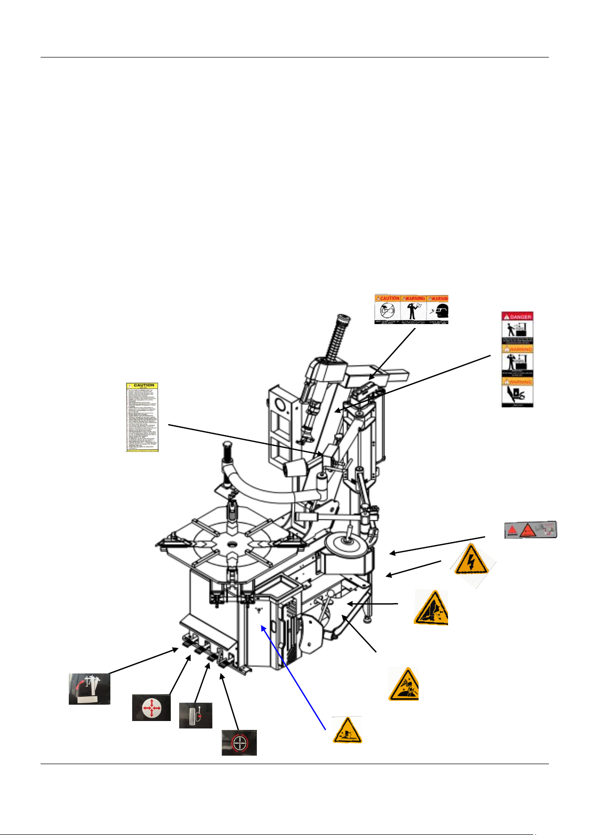
•Illegible and missing warning labels must be replaced immediately. Do not use the tire changer if one or more
labels are missing. Do not add any object that could prevent the operator from seeing the labels.
TIRE AND WHEEL SERVICE SAFETY INSTRUCTIONS
Only properly trained personnel should service tires and wheels. Read all safety and operating instructions thoroughly
before use. The following safety instructions are for one-piece wheels only.
•Always refer to the manufacturer’s procedures for multi-piece wheels.
•The machine must be connected to a power supply line circuit bracket set for 30mA.
•Always keep all working surfaces clean and free of debris.
•Always wear durable personal protective work clothing and safety gear during tire service activity.
•To avoid personal injury and/or machine damage, always make sure the tire rim is firmly secured on the tire changer
with the jaws.
•Always remove all wheel weights and the valve core to deflate the tire before servicing.
•Never place your hands between the vehicle wheel rim and the jaws during the locking/clamping stage.
•Always be aware of what each person is doing and what they will do before attempting any two-person operation.
•Always cover the electric motor and switch box before cleaning the tire changer. Be sure water or cleaner does
not enter the motor or switch box.
•Always disconnect the electric power and air supply before attempting any maintenance.

Aston® Tire Changer ATC-5733 User’s Manual
4
www.astontechusa.com
Demounting & Mounting
•Always clean and inspect the wheel prior to any service.
•Never stand on the frame or work table while demounting or mounting a tire.
•Always keep hands, feet, and other objects away from moving parts while the machine is turned on.
•Always place the narrow bead seat to the outside when clamping. Failure to demount the tire from the narrow bead seat
side may cause damage to the tire beads.
•Always apply an approved rubber lubricant to rim flanges and both tire beads before demounting or mounting and
seating the beads.
•Never mount a tire on a damaged or rusty wheel as tire or wheel failure may result during inflation. Explosion from
failure may result in severe injury or death of the operator and bystanders.
Inflation
•Always be sure the bead opposite the tool is in the drop center before rotating the tire when demounting or mounting to
avoid damage to the tire beads.
•Always follow all applicable Local, State, and Federal Codes, Rules, and Regulations; such as the Federal OSHA
Standard Number 1910.177.
•Always use an approved inflation chamber or inflation cage equipped with a self-gripping chuck and remote inflation
gauge and valve.
•Always inflate the tire to manufacturer’s recommended cold operating pressure.
•DO NOT OVER INFLATE! Tire or wheel failure during and after inflation may result in an explosion capable of causing
severe injury or death.
•Never reinflate a tire that has been run under inflated or flat without first demounting the tire and checking for wheel
and tire damage.
•Always inspect the tire interior for loose or broken cords, cuts, penetrating objects, and other damage. Discard tires that
cannot be properly repaired.
•Never rework, weld, heat or braze wheels.
•Never strike the tire or wheel with a hammer.
•Always be sure the tire diameter exactly matches the wheel diameter.
Danger!
Tire failure under pressure can be hazardous. When possible, always place wheels inside an approved inflation chamber or cage
before inflating. Use an approved remote inflation valve, hose, and gauge. Always wear safety goggles for eye protection. Do
not stand beside the wheel or cage during inflation. Keep hands and other parts of the body out of the cage during inflation.
Observe the tire pressure frequently. Do not exceed the manufacturer’s recommended maximum inflation pressure. Failure to
follow these instructions may cause the tire and rim to separate with tremendous force, resulting in serious personal injury or
death.

Aston® Tire Changer ATC-5733 User’s Manual
5
www.astontechusa.com
Semi-automatic swing arm tire changer
Parameters: rim: 12"-24", Tire width:14"-28", tire diameter: 1190mm
TABLE OF CONTENTS

Aston® Tire Changer ATC-5733 User’s Manual
6
www.astontechusa.com
TABLE OF CONTENTS
Overview...............................................................................................................................................................................8
1.1 Important note .........................................................................................................................................................8
1.2 Qualified users ........................................................................................................................................................8
1.3 Notes .......................................................................................................................................................................8
1.4 Danger warning signs..............................................................................................................................................9
1.5 Noise standard.......................................................................................................................................................10
Equipment description ........................................................................................................................................................10
2.1 Product introduction..............................................................................................................................................10
2.2 Specifications........................................................................................................................................................10
2.3 Transportation .......................................................................................................................................................11
2.4 Figure and part name..........................................................................................................................................11
Installation and commissioning instructions.......................................................................................................................14
3.1 Installation Preparation .........................................................................................................................................14
3.2 Precautions during installation..............................................................................................................................15
3.3 Main installation procedure...................................................................................................................................15
3.4 Check the project table after installation...............................................................................................................16
3.5 Commissioning and debugging.............................................................................................................................16
Operation declaration..........................................................................................................................................................17
4.1 Operating notes .....................................................................................................................................................17
4.2 Disassembly operation process .............................................................................................................................17
5.1 Mounting…………………………………………………………………………………………………………………………………………………………23
Maintenance........................................................................................................................................................................32

Aston® Tire Changer ATC-5733 User’s Manual
7
www.astontechusa.com
6.1 Maintenance..........................................................................................................................................................32
6.2 Storage and scrap ..................................................................................................................................................35
Fault causes and Solutions..................................................................................................................................................36
Parts List and Exploded Drawings...…………………………………………………………………………………........38
Warranty………………………………………………………………………………………………………………………...40

Aston® Tire Changer ATC-5733 User’s Manual
8
www.astontechusa.com
Overview
1.1 Important note
1.1.1 Thank you for your purchase and use of this product. Please read and follow the safety
instructions. Keep them readily available for machine operators.
1.1.2 Service and maintain the unit only with authorized or approved replacement parts.
1.2 Qualified users
1.2.1 Make certain all operators are properly trained, know how to safely and correctly
operate the unit, and are properly supervised.
1.2.2 Electrical appliances must be operated by the normal electrician.
1.2.3 Do not attempt to operate this equipment if you have never been trained on basic tire
service and mounting / dismounting procedures.
1.3 Notes
1.3.1 Before using the product, please carefully read every part of the manual, especially the
operation of the safety and mechanical maintenance of the part.
1.3.2 Use the tire assembly machine must be operated by professional training personnel.
1.3.3 Tire disassemble is forbidden to use in explosive gas.
1.3.4 Before the machine is connected, the user must ensure that the use of power and gas
supply and mechanical requirements, the circuit system must be operated by professional
staff.
1.3.5 In the operation process, do not face close to the turntable, so as to avoid dust and
other debris hit the operator's eyes. In order to ensure safety, mechanical operation, to be
careful, do not touch the inflatable pedal, so as to avoid accidents.
1.3.6 To operate tire inflation must be very careful, strictly according to the instructions for
operation, if the tire suddenly burst, tire assembly machine design and structure is not to
protect the operator's personal safety (or any mechanical in the vicinity of the kind).
1.3.7 Operation of the tire changer, necklace, loose clothing, etc., may give the operator to
bring personal injury.
1.3.8 In the process of removing or installing the operation of the tire, the turntable has
always been to ensure that the clockwise rotation; if there is a counter clockwise rotation
indicates that the turntable is a failure or operator error.

Aston® Tire Changer ATC-5733 User’s Manual
9
www.astontechusa.com
1.3.9 Manufacturers are responsible for the damage caused by the use of other parts of the
manufacturer or the damage of the safety device.
1.3.10 periodically check the oil mist, oil, if the oil level is low and need to unscrew the oil
cup and then add. Oil mist using models for ISO Hg and viscosity for ISO vg32 oil mist
special oil (such as: Esso Fedis k32, 1405, Mobil Vacouline, KLUBER32)
1.3.12 if the product is not used for a long time, please A. disconnect all power supply, B.
and lubricate the turntable fixture slide to prevent oxidation.
1.3.13 when deciding to scrap equipment, to determine the total energy of all the energy to
be cut off, according to the relevant laws and regulations for all non-ferrous metals and non-
ferrous metal scrap processing.
1.4 Warning signs

Aston® Tire Changer ATC-5733 User’s Manual
10
www.astontechusa.com
1.5 Noise standard
The noise of the tire changer shall be less than 70dB. for your health, and it is recommended
that you place a noise meter in your operating area.
Equipment description
2.1 Product introduction
This model of semi-automatic tire changer is a half - automatic, convenient and quick
disassemble and installation of wheel size of 10” to 28”, the tire width of 110-380mm and
the diameter of the tire is 1040mm.
2.2 Specifications
Special points
Technical parameters
Outer rim
12"-24"
Inner rim
14"-28"
Maximum tire diameter
1190mm
Maximum tire width
400mm
Pressing force (10bar)
5510lbs. (2500kg)
Operating air pressure
8bar-10bar(116-145psi)
Maximum charge pressure
3.5bar(50psi)
Power supply voltage
120V 1ph/220V 3ph
Motor power
1.5kw
Outline dimension
Ctn.1:1130*1020*900
Ctn.2:1270*530*420
Net weight
749 lbs. (340kg)
Working state noise
<70dB(A)

Aston® Tire Changer ATC-5733 User’s Manual
11
www.astontechusa.com
2.3 Transportation
Handling of the machine must be performed only with an appropriate lifting device such as a forklift
or pallet jack. Only personnel who are experienced and qualified on material handling procedures
should handle any transportation or moving of machine.
2.4 Figure and part name
G:Wheel Clamp
P:Tower
U:Bead Breaker Pedal
I:Mounting / Dismounting head
R:Bead Breaker
V2:Turntable Pedal
V3: Hypsokinesis
Z: Bead Breaker Pad

Aston® Tire Changer ATC-5733 User’s Manual
12
www.astontechusa.com
Y: Turntable
N: Hypsokinesis arm
K: Locking Handle
Q: Oil Drier
V1: Wheel Clamp Pedal
C: Inflatable
E: Hand Wheel
M: Vertical Reverse Spring
W:Three positions Pressing Arm

Aston® Tire Changer ATC-5733 User’s Manual
13
www.astontechusa.com
E
K
C
P
N
I
G
Y
R
Z
U
V2
V1
Q
M
W
V3

Aston® Tire Changer ATC-5733 User’s Manual
14
www.astontechusa.com
Installation and commissioning instructions
3.1 Installation Preparation
3.1.1 installation location
·The area should provide the operator with enough space to use the equipment in a safe
manner.
·The area selected should be well lit, easy to clean and should be away from oil, grease,
brake lathe chips, etc. Avoid areas where bystanders and customers may be present.
·Equipment installation location should be at least up to the standard shown in Picture,
which can ensure the normal operation and the machine parts are not subject to any
restrictions. The tire changer is forbidden to use in explosive gas.
3.1.2 Installation equipment and tools
◇Installation equipment and tools
3.1.3 inspection products

Aston® Tire Changer ATC-5733 User’s Manual
15
www.astontechusa.com
◇The shipment should be thoroughly inspected as soon as it is received. The signed Bill
of Lading is acknowledgement by the shipping carrier as receipt of this product as listed
in your invoice as being in a good condition of shipment. If any of these goods listed on
this Bill of Lading are missing or damaged, do not accept goods until the shipping carrier
makes a notation on the freight bill of the missing or dam- aged goods. Do this for your
own protection.
3.1.4 Unpacking
◇Check the packaging damage and
the rain and other damage
phenomenon, using the tool unpack
the packing as shown in Picture,
please dispose of packaging box,
lest the environmental pollution.
◇Check the condition of the machine,
in accordance with the packing list
to check if there is any damage or
lost, once found contact the dealer
and manufacture immediately. If
you find that the leakage but still
installed, we will not assume any responsibility. If you have any questions, please do not
use the machine, the supplier contact.
3.2 Precautions during installation
◇All bolts must be tightened.
◇Power cord, no broken skin, no broken pipe, and other damage.
3.3 Main installation procedure
3.3.1 Standard configuration installation
◆The first step: Place the machine on the chosen place, and then fix it to the ground by
fixing screw.
◆The second step: Lift the tilting arm and insert the PU hose (G) into the hole (Fig3).
Figure 5

Aston® Tire Changer ATC-5733 User’s Manual
16
www.astontechusa.com
(Do not bend the hose) Then take out the part A (shown in Fig.3) from the accessory box,
unscrew the cap on the top of part A, insert the part A into the hole that go through the
main box of the machine and the bottom of the tilting arm, then tighten the bolt.
◆The third step: Take out the part B (shown in Fig.3) from the accessory box, unscrew the
spring on one side of part B, then insert part B into the hole that go through the part D,
E, then screw the spring. Take out the side panel on the side of the machine. Connect the
PU hose (G) that go through the main box of the machine with the part F.
◆The forth step: mount the part E on the arm (Fig.4), then mount parts D, C, B, A, G, F
in sequence. During the operation, pay attention to the PU hose and other parts.
3.4 Check the project table after installation
No.
Inspection item
Yes
No
Remarks
1
Whether the power supply voltage is consistent
with the requirements of the equipment
2
Whether the components are installed correctly
3
Whether the bolts, screws, nuts are tightened
Note: Please fill in the inspection item list after the installation is finished.
3.5 Commissioning and debugging
3.5.1 Commissioning
◇After the installation of the machine but before the connection with the power supply, it
is necessary to determine the user's power supply, the gas source and the requirements
Figure 6-c

Aston® Tire Changer ATC-5733 User’s Manual
17
www.astontechusa.com
of the machine is consistent.
◇The machine is connected to the circuit, the circuit must be fitted with a fuse that is in
line with the operating rules. The automatic circuit breaker of 25A is required to be
operated by professional personnel. The power plug of the tire changer is provided with
the customer.
◇The compressed air system is connected to the machine by a pipe joint on the right side
of the tank.
3.5.2 Debugging
◇Step 1: turn on the power and gas supply, depress the Turntable Rotation pedal, turntable
should be clockwise. Raise the Turntable Rotation pedal, the turntable should be anti-
clockwise rotation. (If the turntable is opposite to the specified rotation direction, the
position of the two lines in the three-phase plug should exchange position.)
◇The second step: depress the Bead Breaker Pedal, start the Bead Breaker device; when
the pedal is released, the Bead Breaker device to return to the original position.
◇The third step: depress the Jaw Clamp Pedal, open the 4 clamps; release the Jaw Clamp
Pedal, the Jaw Clamps returns to the original position.
Operation declaration
4.1 Operating notes
◇Check the connection of air pipe is in place, ensure that no air leakage, ensure the
operation space to meet the requirements, then start work.
◇Before any operation, the gas in the tire is needed to be released, and the balance block
of the tire balancing device is removed.
4.2 Disassemble operation process
4.2.1 Bead Loosening
◇Deflate tire completely by removing the valve core from the valve stem. To avoid
damaging the clamps and/or wheel, move the clamps to their full inward position before

Aston® Tire Changer ATC-5733 User’s Manual
18
www.astontechusa.com
positioning a tire for bead loosening.
◇Pull the bead breaker blade away from the machine and roll the wheel into position. If
servicing a performance wheel or any other wheel with Tire Pressure Sensor), make sure
that the valve stem is either in the 12 o’clock or 6 o’clock position.
◇Position the bead breaker blade against the tire next to, but not on, the rim or the sidewall
of the tire. Press the breaker pedal to actuate the blade and loosen the bead. It may be
necessary to loosen the bead in multiple locations around the tire. Use extra care in
positioning the bead breaker blade on larger wheels/tires, and on alloy wheels.
◇Turn wheel around and repeat procedure on the other side of the wheel. This should be
the long side of the drop center. It will be easier to clamp the wheel to the table top if
the lower bead is loosened last.
◇Determine the mounting side of the wheel. The mounting side is the narrow side of the
drop center.

Aston® Tire Changer ATC-5733 User’s Manual
19
www.astontechusa.com
4.2.2 Wheel Clamping
◇Fixed the block in the Right helper arm in the center of
Press Wheels.
◇Use the Wheel Clamp Foot Pedal to move the Clamps inward (pedal down) or outward
(pedal up).
4.2.3 Tire mounting
◇Apply tire manufacturer’s approved rubber lubricant liberally to entire circumference
of both upper and lower beads after loosening bead and placing on table top.
◇After the wheel is secured to the Turntable, set the vertical shaft in the working position.
◇Push the Vertical Shaft down and position the Mount/ Demount Head into contact with
the rim edge.
◇Press the button on the locking handle to lock. As the slide is locked, the Mount/
Demount Head will move upward approximately 1/8 inch and backward 1/8 inch from
the rim edge. The Mount/Demount head roller should not be in contact with the rim edge.
◇Place tire/wheel assembly on
Table Top with mounting side up.

Aston® Tire Changer ATC-5733 User’s Manual
20
www.astontechusa.com
◇Lift the bead onto the mount/demount head with the bead lifting tool, and step on the
turntable control pedal to turn the turntable clockwise till the upper bead is completely
separated.
NOTE:
THIS CLEARANCE WILL BE MAINTAINED AS LONG AS THE VERTICAL SHAFT REMAINS
LOCKED. THE OPERATOR MAY SWING THE ARM OUT OF THE WAY AND BACK INTO PLACE
AGAIN WITHOUT NEEDING TO REPOSITION THE HEAD WHEN CHANGING A LIKE SET OF
WHEELS. THE TOOL CLEARANCE MAY CHANGE WITH MACHINE USE AND SHOULD BE
INSPECTED OFTEN. FAILURE TO MAINTAIN PROPER CLEARANCE MAY RESULT IN DAMAGE
TO THE WHEEL RIM OR TIRE.
THE BEAD LIFTING TOOL AND DEMOUNT HEAD MAY ENCOUNTER RESISTANCE OR COME
UNDER LOAD AT TIMES DURING THE MOUNT AND DEMOUNT PROCEDURES. KEEP ONE HAND
FIRMLY ON THE TOOL TO AVOID POSSIBLE TOOL KICK BACK. USE THE REVERSING FEATURE
(LIFT TABLE TOP PEDAL UPWARDS) TO BACK OUT OF JAM UPS.
Table of contents
Other Aston Global Tyre Changer manuals
Popular Tyre Changer manuals by other brands

Butts of Bawtry
Butts of Bawtry TCS0022 User Instructions & Parts List

Mondolfo Ferro
Mondolfo Ferro AS 924 Operator's manual

GIULIANO
GIULIANO PRESS ARM instructions

Mondolfo Ferro
Mondolfo Ferro Startline S 524 Operator's manual

Fasep
Fasep RASE.TOP.2248 instruction manual

HPA-Faip
HPA-Faip M 830 LL Operator's manual