Astraada AS54 User manual

Industrial PC: Astraada PC AS54
USER MANUAL

Astraada PC AS54
- 2 -
Manual Conventions
WARNING:
Warnings appear where overlooked details may cause damage to the equipment or
result in personal injury. Warnings should be taken seriously.
CAUTION:
Cautionary messages should be heeled to help reduce the chance of losing data or
damaging the product.
NOTE:
These messages inform the reader of essential but non-critical information. These
messages should be read carefully as any directions or instructions contained therein
can help avoid making mistakes.

Astraada PC AS54
- 3 -
Content
Chapter 1 Overview .............................................................Błąd! Nie zdefiniowano zakładki.
1.1 Introductions................................................................................................................- 5 -
1.2 Key Features................................................................................................................- 5 -
1.3 External Overview.......................................................................................................- 5 -
1.4 Specifications ..............................................................................................................- 6 -
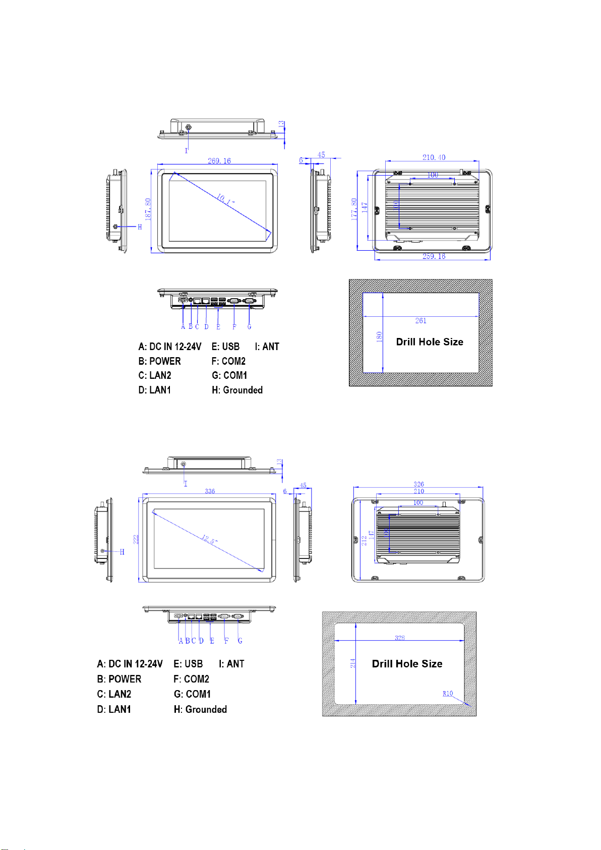
1.5 Dimensions..................................................................................................................- 8 -
Chapter 2 Hardware Installation......................................................................................... 12
2.1 Unpack the panel PC..................................................................................................... 13
2.2 Packing list.................................................................................................................... 14
2.3 Mounting methods......................................................................................................... 15
2.4 IO connectors ................................................................................................................ 20
2.5 Power connector............................................................................................................ 22
2.6 Connectors Definitions.................................................................................................. 23
Chapter 3 Driver installation ............................................................................................... 26
3.1 General introduction...................................................................................................... 27
3.2 Chipset driver ................................................................................................................ 27
3.3 Graphics driver.............................................................................................................. 30
3.4 Audio driver .................................................................................................................. 33
3.5 LAN driver.................................................................................................................... 35
Chapter 4 BIOS Setup .......................................................................................................... 39
4.1 BIOS Setup.................................................................................................................... 40
Chapter 5 System installation............................................................................................... 53
5.1 System Maintenance Introduction................................................................................. 54
5.2 Cover Removal.............................................................................................................. 54
Appendix A Safety Precautions............................................................................................ 55
A.1 General Safety Precautions...................................................................................... 55
A.2 Anti-static Precautions............................................................................................. 56
A.3 Disposing of the Equipment.................................................................................... 57
A.4 Maintenance and Cleaning Precautions.................................................................. 58

Astraada PC AS54
- 4 -
Chapter 1
Overview

Astraada PC AS54
- 5 -
1.1 Introductions
The AS54FXXC series is a fanless industrial panel computer based on the design of a
projected capacitive touch panel. It has a smooth multi-touch experience and stylish
design. The connection between the display panel and the host adopts a reliable
modular design. A variety of host specifications can be selected, and customers can
quickly upgrade and maintain without changing the customer's original design, so
that customers will not be hindered in future product upgrade selection, testing,
production and maintenance.
Supports: Windows 7, Windows 8, Windows10, Linux.
Size: 10.1”, 12.1”, 12.5”, 15”, 15.6”, 19”, 21.5”.
1.2 Key Features
➢The front panel is treated with die-casting aluminum-magnesium alloy to reach
IP65 protection level;
➢Mg-Al alloy plate and sheet metal box structure
➢Multi-point projected capacitive touch screen
➢The hard disk supports mSATA.
➢Intel J1900 quad-core processor, clocked at 2.0GHz, TDP is 10W
➢2x Intel i210 10/100/1000Mbps Ethernet
➢DC IN/2 x GLAN/ 4 x USB/2x COM
➢2 x RS-232/485 (in option)
1.3 External Overview
Figure 0-1 External overview of AS54FXXC

Astraada PC AS54
- 6 -
1.4 Specifications
Processor
CPU
Intel® Celeron J1900
Main Frequency
Quad-core 2.0 GHz
L2 Cache
2MB
Chipset
Intel Bay Trail
RAM
Support DDR3L-1333 MHz, 1 * 204-pin SODIMM, Up to 8GB
Storage
1 * mSATA
Ethernet
LAN1
Intel i210 Gbe LAN controller, RJ-45
LAN2
Intel i210 Gbe LAN controller, RJ-45
I/O
Audio
Realtek ACL662, Line-out
Serial port
2 x RS-232(RS-485 in option) Interface with surge protection
USB
1* USB3.0+3* USB2.0
Rear I/O
2* GLAN/ 4*USB/ 2*COM/ DC IN
MiniPCIe
1 * MINI- PCIe slot, extended to 3G and wifi card
OS
OS
Windows 7, Windows8, Windows10, Linux
Power
DC Input
12-24V DC, 60W
Touchscreen
Screen type
Multi- points Capacitive touch screen
Transmittance
≥87%
Controller
USB interface
Driver support
Windows 7, Windows8, Windows10, Linux
Surface Hardness
Mohs Hardness 7H
Multi-touch
10 points when using Windows system
Environmental
Operating
Temperature
-10 ~ 50° C (14 ℉~122 ℉) Use a wide temperature grade SSD
-20 ~ 60° C (-4 ℉~140 ℉) Use HDD
Storage
Temperature
-30 ~ 80℃(-22 ~ 176 ℉)
Relative Humidity
10~95% RH@40°C,non-condensing
Vibration
SSD applied: 1.5 Grms, IEC 60068-2-64, random, 5 ~ 500 Hz, 1 hr/axis
Shock
SSD applied: 10 G, IEC 60068-2-64, Half-sine wave, 11ms duration
EMC
CE/FCC Class A
Water-proof
Front panel IP65
Type
AS54F10C
AS54F12C
AS54F13C
AS54F16C
Physical
Dimensions
269x188x45mm
315x250x47mm
336x222x45mm
368x292x55mm
(W x H x D)
10.6x7.40x1.77”
12.40x9.84x1.85"
13.23x8.74x1.77”
14.5 x 11.5 x 2.17"
Drill Hole Size
261 x 180mm
307x 242mm
328 x 214mm
358 x 282mm
(W x H)
10.28 x 7.09"
12.09 x 9.53"
12.91x8.43”
14.09 x 11.1"
Net Weight
1.84kg
2.75kg
2.46kg
3.98kg
Max. power
consumption
31.2W
31.6W
32.9W
38.6W

Astraada PC AS54
- 7 -
LCD
LCD type
10.1” TFT
12.1'' SVGA TFT
12.5'' TFT
15"XGA TFT
Resolution
1280 x 800
1024*768
1366*768
1024*768
Colors
16.7M
16.7M
16.7M
16.7MB
Active Area
216.96 x 135.6mm
346x184.5mm
275.59x154.94mm
304.13 x 228.10mm
(W x H)
8.54 x 5.33"
9.68 x 7.26"
10.85 x 6.1"
11.97 x 8.98"
Backlight
LED
LED
LED
LED
MTBF (Hour)
15000hrs
30000hrs
25000hrs
30000hrs
Pixel Pitch
(H x V)
0.1695 × 0.1695
0.3075 x 0.3075
0.218 x 0.218
0.297 x 0.297
Luminance
350cd/m2
350cd/m1
300cd/m2
420cd/m2
Contrast Ratio
800:1
800:1
800:1
800 : 1
Viewing Angle
(L)85/(R)85/(T)85/
(B)85
(L)85/(R)85/(T)85/
(B)85
(L) 85/(R)85/(T)85/
(B)85
(L)80/(R)80/(T)60/
(B)80
Type
AS54F16C
AS54F19C
AS54F22C
Physical
Dimensions
400x 257x 45mm
459 x 383 x 55mm
549 x 340 x 55mm
(W x H x D)
15.75 x 10.12 x 1.77"
18.07 x 15.08 x 2.17”
21.6 x 13.4 x 2.17”
Drill Hole Size
392 x 249mm
449 x 373mm
539 x 330mm
(W x H)
15.43 x 9.8"
17.68 x 14.69”
21.22 x 12.99”
Net Weight
3.09kg
6.09kg
6.22kg
Max. power
consumption
35.8W
42.6W
46.4W
LCD
LCD type
15.6'' TFT
19" SXGA TFT
21.5" Full HD TFT
Resolution
1920 ×1080
1280 x 1024
1920 x 1080
Colors
16.7M
16.7MB
16.7MB
Active Area
344.16 x 193.59mm
376 x 301mm
476.64 x 268.11mm
(W x H)
13.55 x 7.62"
14.82 x 11.85"
18.77 x 10.56"
Backlight
LED
LED
LED
MTBF (Hour)
15000hrs
30000hrs
30000hrs
Pixel Pitch
(H x V)
0.179 x 0.179
0.294 x 0.294
0.248 x 0.248
Luminance
350cd/m1
250cd/m2
250cd/m2
Contrast Ratio
800:1
1000 : 1
3000:1
Viewing Angle
(L)85/(R)85/(T)85/(B)85
(L)85/(R)85/(T)80/(B)80
(L)89
/(R)89/(T)89/(B)89

Astraada PC AS54
- 8 -
1.5 Dimensions
Figure 0-2 Dimension of AS54F10C
Figure 0-3 Dimension of AS54F13C

Astraada PC AS54
- 9 -
Figure 0-4 Dimension of AS54F12C
Figure 0-5 Dimension of AS54F16C

Astraada PC AS54
- 10 -
Figure 0-6 Dimension of AS54F15C
Figure 0-7 Dimension of AS54F19C

Astraada PC AS54
- 11 -
Figure 0-8 Dimension of AS54F22C

Astraada PC AS54
12
Chapter 2
Hardware Installation

Astraada PC AS54
13
CAUTION:
There might be a risk of electric shock. Please always disconnect or turn off the main
power before and during the installation.
Incorrect settings can cause irreparable damage to the product. Only certified
engineer can change settings of the hardware.
2.1 Unpack the panel PC
WARNING:
Failure to take electrostatic discharge precautions during the installation of the
product may result in permanent damage to the product and severe injury to the
user.
Please follow the steps below to unpack your panel PC:
Step 1: Carefully cut the tape stealing outside the box,
Step 2: Open the box,
Step 3: Carry the panel PC out of the box,
Step 4: Carry out the accessory box.

Astraada PC AS54
14
2.2 Packing list
NOTE:
If some of the components listed in the checklist below are missing, please do not
proceed with the installation. Contact the sales representative or vendor you
purchased the product from.
Table 2-1 Package list
Item
Image
Quantity
AS54FXXC
1
Power cord
1
Power adapter
1
Mounting clamps (1)
On the device
Mounting clamps (2)
8

Astraada PC AS54
15
2.3 Mounting methods
CAUTION:
Make sure that installing the product with assistance, since the product is very heavy
and could be damaged by falling and collision.
Multiple types of mounting methods are available for AS54FXXC installation. You can
choose the best way you want.
2.3.1 Desk-top support
AS54FXXC is designed to be installed on desk-top stand. For the installation
introduction, please follow the manual of the stand.
Figure 2-1 Desk-top stand

Astraada PC AS54
16
2.3.2 Arm mounting
AS54FXXC is designed to be VESA mounted with the mounting bracket shows in
Figure 2-2.
Figure 2-2 Arm mounting of AS54FXXC
NOTE:
The AS54FXXCuses a VESA mounting to attach to the arm. Please make
sure that the arm supports a standard VESA mounting.
Please follow the steps below to install:
Step 1: Follow the instructions in the arm’s user manual to securely attach the arm
to the wall.
Step 2: Once the mounting arm has been firmly attached to the wall, lift the panel PC
onto the interface pad of the mounting.
Step 3: Align the screw holes of the mounting arm to the screw holes of the panel
PC.
Step 4: Insert four retention screws through the bottom of the mounting arm
interface pad and into the panel PC. Then screw the screws.

Astraada PC AS54
17
2.3.3 Wall mounting
AS54FXXCis designed to be wall mounted with the mounting bracket shows in
Figure 2-3.
Figure 2-3 Wall mounting
Please follow the steps below to install:
Step 1: Select the location on the wall for the wall-mounting bracket.
Step 2: Carefully mark the locations of the four bracket screw holes on the wall.
Step 3: Drill four pilot holes at the marked locations on the wall, for the bracket
retention screws.
Step 4: Align the wall-mounting bracket screw holes with the pilot holes.
Step 5: Secure the mounting-bracket to the wall by inserting the retention screws
into the four pilot holes and tightening them.
Step 6: Insert the four monitor mounting screws provided in the wall mounting kit
into the four screw holes on the real panel of the panel PC. Then screw screws until
the screw shank is secured against the rear panel.
Step 7: Align the mounting screws on the monitor rear panel with the mounting
holes on the bracket.

Astraada PC AS54
18
Step 8: Carefully insert the screws through the holes and gently pull the monitor
downwards until the monitor rests securely in the slotted holes. Ensure that all four
of the mounting screws fit snuggly into their respective slotted holes.
Step 9: Secure the panel PC by fastening the retention screw of the wall-mounting
bracket.
2.3.4 Panel mounting
There are two ways to mount the AS54FXXCinto a panel:
For AS54F10C, AS54F13Cand AS54F16C, the clamps (mounting clamps (1) in
Table 2-1) are on the device. To install the panel PC, please follow the steps below:
Step 1: Select the location on the panel to mount the panel PC.
Step 2: Drill holes in selected positions according to the drill hole size of the panel
PC.
Step 3: Slide the panel PC through the hole until the frame is flush against the panel.
Step 4: Loosen the Phillips screw and rotate the oval hook 90 degrees.
Step 5: Tighten the screws that pass through the panel mounting clamps until the
caps at the front of all the screws are firmly secured to the panel.
Figure 2-4 Locking position of the clamps

Astraada PC AS54
19
For AS54F21C, AS54F15C, AS54F19Cand AS54F22C, the Clamps are in the
accessory box. To install the panel PC, please follow the steps below :
Step 1: Select the location on the panel to mount the panel PC.
Step 2: Drill holes in selected positions according to the drill hole size of the panel
PC. Make sure that the cut out is smaller than the overall size of the metal frame
that surrounds the panel PC but just large enough for the rear panel of the panel PC
to fit through.
Step 3: Slide the panel PC through the hole until the frame is flush against the panel.
Step 4: Insert the panel mounting clamps into the pre-formed holes along the edges
of the chassis, on the two side of the frame.
Step 5: Tighten the screws that pass through the panel mounting clamps until the
caps at the front of all the screws are firmly secured to the panel.
Figure 2-5 Right position of the clamps

Astraada PC AS54
20
2.4 IO connectors
The IO connectors extend the capabilities of the panel PC but are not essential for
operation (except power).
Figure 2-6 IO interface of AS54FXXC
2.4.1 LAN connection
The RJ-45 connectors enable connection to an extend network. To connect a LAN
cable with a RJ-45 connector, please follow the instructions below.
Step 1: Locate the RJ-45 connector on the bottom panel of the AS54F (see Figure 2-
6).
Step 2: Align the RJ-45 connector on the LAN cable with one of the RJ-45 connector
on the bottom panel of the AS54FXXC (see Figure 2-7). Then, gently insert.
Figure 2-7 LAN connection
Step 3: Screw the retention screws on both side of the connector to secure the
connection.
A: DC IN 12-24V E: USB
B: POWER F: COM2
C: LAN2 G: COM1
D: LAN1
This manual suits for next models
6
Table of contents