Astrea Evolve Manual

Technical User Guide
Evolve™Process Columns
(200 & 250mm diameter columns)

PC: Evolve 200_250 Columns Operating Manual v2
1

PC: Evolve 200_250 Columns Operating Manual v2
2
Contents
Table of Figures..........................................................................................................................4
1. Column Hardware.................................................................................................................. 5
Mechanical Description: ........................................................................................................ 5
Design features:...................................................................................................................... 5
Technical data ........................................................................................................................6
Weights and Dimensions .......................................................................................................6
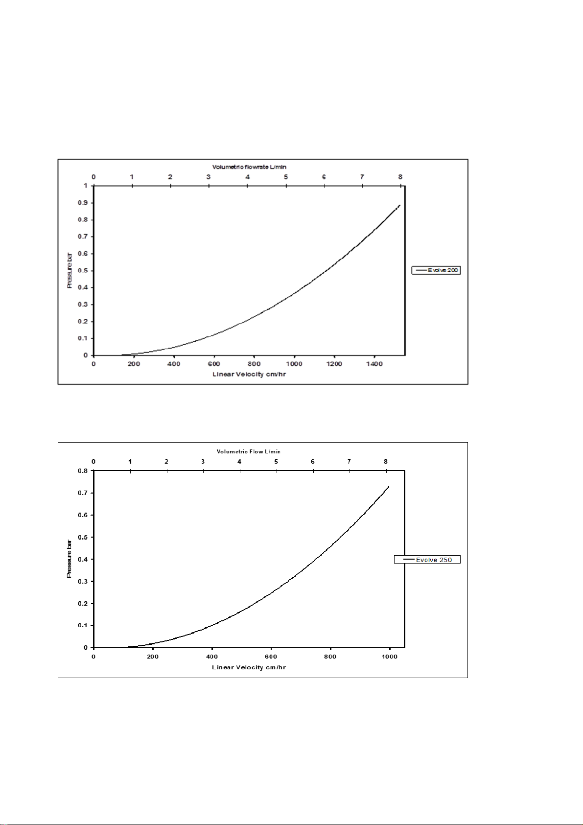
Pressure Drop......................................................................................................................... 7
Material Conformity...............................................................................................................8
Materials of Construction – Process-Wetted Parts............................................................8
Materials of Construction – Non Process-Wetted Parts....................................................8
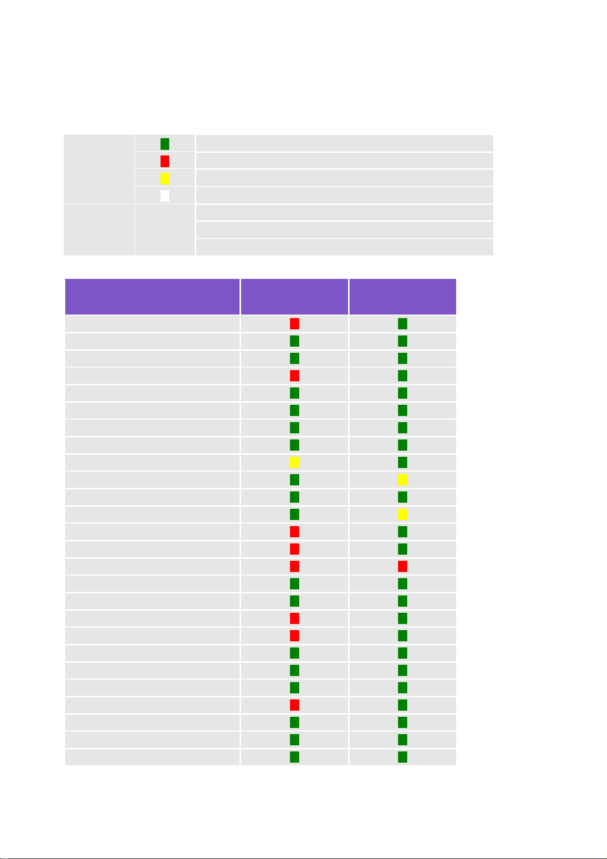
Chemical Compatibility.......................................................................................................... 9
2. Safety Guidelines...................................................................................................................11
Safety considerations ............................................................................................................11
Pressure Equipment Directive (PED)...................................................................................11
Over-Pressurization ..............................................................................................................11
Handling................................................................................................................................11
Chemical compatibility .........................................................................................................11
3. Column Installation and Operation......................................................................................12
Column Installation ..............................................................................................................12
(1) Installation of bed supports .........................................................................................12
(2) Installation of Fixed Bed Support................................................................................12
(3) Installation of Height Adjustable Feet.........................................................................13
(4) Levelling the Evolve™ Process Columns.....................................................................13
(5) Installation of Adjuster Bed Support...........................................................................14
(6) Setting the Bed Height.................................................................................................15
4. Column Operation ................................................................................................................16
Hydrostatic Leak Test ...........................................................................................................16
Column Packing (Constant Flow Rate Method) ...................................................................17
Unpacking ............................................................................................................................20
Cleaning................................................................................................................................20
Storage..................................................................................................................................20
5. Maintenance..........................................................................................................................21
Routine Maintenance Procedures and General Guidelines..................................................21
Disassembly of Evolve™ Process Columns.......................................................................... 22
Adjuster Assembly............................................................................................................22
Fixed Assembly................................................................................................................. 23
Tube Assembly..................................................................................................................24

PC: Evolve 200_250 Columns Operating Manual v2
3
Reassembly of Evolve™ Process Columns...........................................................................24
Fixed Assembly.................................................................................................................24
Adjuster Assembly............................................................................................................ 25
6. Troubleshooting...................................................................................................................28
Leakage from Adjuster Seal..................................................................................................28
Leakage from Fixed Bed Support Seal .................................................................................28
Leakage from Inlet or Outlet................................................................................................28
Excessive Column Back Pressure.........................................................................................28
Media Leakage......................................................................................................................29
7. Ready to Use.........................................................................................................................30
Kits supplied with Column...................................................................................................30
Tool kit .................................................................................................................................30
Connection kit ......................................................................................................................30
Spares Kit ..............................................................................................................................31
8. Spare Parts, Kits & Accessories ........................................................................................32
Column Refresh Kit..............................................................................................................32
Wetted Flow path Kit ...........................................................................................................33
Bed Support Kit....................................................................................................................33
Elastomer Seal Kit................................................................................................................34
Adjuster Cell Kit...................................................................................................................34
Torque Wrench Kit............................................................................................................... 35
Fixed Cell Kit........................................................................................................................ 35
Fluid Connection Kit (200 & 250 mm diameter columns).................................................. 35
Flexible Hose (200 & 250 mm diameter columns).............................................................. 35
Adjustable Foot Kit...............................................................................................................36
9. Chromatography Performance......................................................................................... 37

PC: Evolve 200_250 Columns Operating Manual v2
4
Table of Figures
Figure 1 Pressure Drop Evolve™ 200 mm Process Column 7
Figure 2 Pressure Drop Evolve™ 250 mm Process Column 7
Figure 3 Diagram showing the location of the fixed bed support 12
Figure 4 Photograph showing the installation of the fixed bed support 13
Figure 5 Height Adjustable Feet 14
Figure 6 Diagram showing the location of the adjuster bed support 14
Figure 7 Photograph showing the location of the adjuster bed support 15
Figure 8 Schematic of the column with part identification 19
Figure 9 Adjuster Assembly for EvolveTM 250 Process Column 22
Figure 10 Fixed Assembly for EvolveTM 250 Process Column 23
Figure 11 Position of the support blocks before the fixing bolts 23
are completely removed
Figure 12 Diagram showing the location of the fixed bed support 24
Figure 13 Photograph showing the installation of the fixed bed support 24
Figure 14 Position of fixed end support blocks to enable relocation 25
of the flow cell
Figure 15 Diagram showing the location of the adjuster bed support 26
Figure 16 Photograph showing the final location of the adjuster bed support 26
Figure 17 Photograph showing the alignment of markings on flow tube and
sanitary clamp adapter to ensure component is correctly tightened 27
Figure 18 Description of Column Efficiency Calculations 37

PC: Evolve 200_250 Columns Operating Manual v2
5
1. Column Hardware
Mechanical Description:
Evolve™ Process Columns are designed specifically for use in
biopharmaceutical applications and can be used in both pilot and
production scale chromatographic processes.
A pressure rating of 4 bar, operating temperature range of 2-30°C
and adjustable bed height makes this column suitable for a wide
range of chromatography media types and chromatographic
techniques.
Design features:
1. The entire flow path is non-metallic, which has the following advantages;
a. Eliminates the corrosion risk and contamination of the process.
b. Allows the use of high concentration sodium chloride and guanidine hydrochloride
solutions.
c. Prevents any product inactivation through metal contact.
2. Unlike other columns available on the market the Evolve™ Process Columns have an integral
bed support and seal assembly. The polypropylene mesh and seal are manufactured as a
single unit and fits directly on the flow cell without any fixings, which has the following
advantages;
a. Ensures the maximum area is available to flow, promoting good chromatographic
performance and clean ability.
b. Eliminates use of fixings to secure the bed support to the flow cell, removing the
potential for leak paths or dead flow zones.
c. Reduces number of components in the column assembly, leading to easy operation
and maintenance.
3. Sealing of the adjuster flow cell to the tube wall is achieved by a moulded Santoprene®
seal. Central activation of this seal ensures that compression is even. The mechanism to
energise and de-energise the seal is simple and easy to operate.
4. Positioning of the adjuster assembly within the acrylic tube is easy and simple using the
central adjustment mechanism.
5. The column is composed of three main sub-assemblies –
a. Adjuster assembly - which consists of the adjuster flow cell assembly, adjuster seal
components, adjuster flange and a central height adjust rod. This allows the
position of the adjuster to be varied using the height adjust rods over the range 20-
520 mm.
b. Tube unit - which consists of the acrylic column tube, flanges and column stand or
support legs.
c. Fixed assembly - which consists of the bottom flow cell assembly and flow tube.

PC: Evolve 200_250 Columns Operating Manual v2
6
Technical data
Column:
200 250
Product Code AB200505 AB250505
Tube i.d. (mm) 200 250
Cross sectional area (cm2) 314.2 490.9
Maximum bed height (cm) 520 520
Minimum bed height (cm) 20 20
Max. column volume (L) 16.3 25.5
Adjustable capacity (L)
15.7 24.5
Pressure rating (bar/psi) 4/ 58 4/ 58
Operating temperature
2 to 30°C
Bed support size 8µm
Weights and Dimensions
Column:
200 250
Product Code AB200505 AB250505
Adjuster Weight (kg) 12.7 15
Total weight empty (kg) 45.5 52
Total Weight Full* (kg) 60 76
Maximum diameter excluding casters (mm) 455 495
Maximum diameter including casters (mm) 455 495
Maximum height (mm) 1550 1550
Minimum clearance** (mm) 1750 1750
*based on bed height of 520 mm and specific gravity 1.05
**minimum height required to remove adjuster from acrylic tube unit

PC: Evolve 200_250 Columns Operating Manual v2
7
Pressure Drop
The pipework and column contribute to the pressure drop of the chromatographic system.
Measuring the pressure drop from the column inlet to the column outlet shows the contribution
made by the column hardware. The tests were performed at ambient temperature 15-20°C using RO
water.
Figure 1 Pressure Drop Evolve™ 200 mm Process Column
Figure 2 Pressure Drop Evolve™ 250 mm Process Column

PC: Evolve 200_250 Columns Operating Manual v2
8
Material Conformity
All materials in contact with the process stream have been selected for their suitability for use in
equipment utilised in biopharmaceutical applications and so either conform to relevant sections of
FDA code of Federal Regulations vol. 21 170-199 and/or have passed USP class VI test for in vivo
toxicity.
Materials of Construction – Process-Wetted Parts
Column Component
Material
Column tube Acrylic
Fixed flow tube Polypropylene
Adjuster flow tube Polypropylene
Sanitary clamp adapters 20% glass filled polypropylene
Bed supports Polypropylene
Fixed bed support seal Santoprene®
Adjuster seal Santoprene®
Flow tube seal (fixed and adjuster) Santoprene®
Adjuster bed support seal Santoprene®
Fixed flow cell Polypropylene (black)
Adjuster flow cell Polypropylene (black)
Anti-jet disc 20% glass-filled polypropylene
Sanitary clamp seals Santoprene® elastomer
Pipe spool Polypropylene
Materials of Construction – Non Process-Wetted Parts
Column Component
Material
Adjuster flange, tube flange and fixed flange, fixed flow cell
back plate (200 & 250 mm only) Acetal black
Seal adjust boss, seal adjust tube Stainless steel
Threaded central adjust rod Acetal black
Seal adjust handles (70 mm and100 mm), pipework clamp Acetal blue
Seal adjust handles (140 mm, 200 mm and 250 mm) Stainless steel/Acetal blue
Lifting eye (200 mm and 250 mm only) Stainless steel 316
Support Leg Stainless steel 316
Foot (200 mm and 250mm only) Stainless steel with rubber
Bolts, screws, washers Stainless steel type 316

PC: Evolve 200_250 Columns Operating Manual v2
9
Chemical Compatibility
Acrylic columns are ideally suited for aqueous-based applications. See the table below for detailed
compatibility information.
Key:
Resistance
Resistant; suitable for continuous use
Not resistant; not recommended
Limited resistance
No information available
Notes
General All solvents are at 100% concentration unless noted otherwise
Concentrations: % refer to w/w
All data is referenced to room temperature (15º–25ºC)
Chemical
Wetted Components
Non wetted Stainless
Steel 316L
1,2-dichloroethane
Acetic acid 25%
Acetone 5%
Acetonitrile
Ammonia aqueous <25%
Ammonium sulphate 10-40%
Benzyl alcohol 1%
Benzyl alcohol 2%
Butanol
Calcium chloride 2
Calcium hydroxide 30%
Calcium hypochlorite
Chloracetic acid 50%
Chloroform
Chromic acid 10%
Citric acid
Copper sulphate
Dichloromethane
Dimethyl formamide
Dimethyl sulphoxide 10%
Disodium phosphate
Ethanol 20%
Ethanol 70%
Ethylene glycol (1,2-ethanediol)
Formaldehyde 50%
Glycerol (Glycerine)

PC: Evolve 200_250 Columns Operating Manual v2
10
Chemical Wetted
Non Wetted
Stainless Steel 316L
Guanidine hydrochloride 6.0 M
Hydrochloric acid 10%
Hydrofluoric acid
Hydrogen peroxide
Industrial methylated spirit (IMS)
Methanol 20%
Methanol 50%
Methyl chloride (Chloromethane)
Methyl ethyl ketone (MEK)
Methylene chloride
Nitric acid 10%
Nitric acid 70%
Peracetic acid 300 ppm
Phosphoric acid < 55%
Potassium hydroxide 2.0 M
Iso-propanol 20%
Iso-propanol 40%
n-propanol 20%
Sodium acetate
Sodium bicarbonate 20%
Sodium carbonate
Sodium chlorate
Sodium chloride 2.0 M
Sodium chloride 6.0 M
Sodium hydroxide 0.5 M
Sodium hydroxide 2.0 M
Sodium hypochlorite 200 ppm
Sodium nitrate
Sodium sulphate
Trichloroethene
(Trichloroethylene)
Triton™ X-100 surfactant
Urea 6.0 M
Zinc chloride

PC: Evolve 200_250 Columns Operating Manual v2
11
2. Safety Guidelines
Safety considerations
•Please read through this user guide prior to use to ensure safe and careful handling of the
product
•Please follow all local laws and regulations for safe disposal for laboratory and
manufacturing production use only and is not for administration into humans
•Please take care when moving or handling the columns as they can weigh up to 26 kg (when
packed)
Pressure Equipment Directive (PED)
European Pressure Directive 97/23/EC relates to regulations that are mandatory and govern a wide
range of pressure containing vessels. The design and manufacture of chromatography columns,
including the EvolveD™columns, are affected by these regulations.
The regulations are divided into categories, and the EvolveD™ column range has been assessed and
found that it falls within the Sound Engineering Practice (SEP) category. The foundation of the
assessment is based on the following;
•The range of Evolve™Process columns are liquid chromatography columns and when used in
accordance within their Operating Instructions there should be no gas e.g. air present in the
columns
•The substances that will be used in the column will remain in liquid form during the entire
operation at the maximum stated operating temperature.
In addition:
• The maximum pressure is less than 6 bar
• The product pressure x volume is equal to or less than 200 bar litres.
Over-Pressurization
Users of the Evolve™ Process Columns must ensure that the maximum operating pressure is not
exceeded. It is recommended that an over-pressurization protection device such as a ‘Pressure
Relief Valve’ or equivalent is utilised.
Handling
Care should be taking when handling the Evolve™ Process Columns. Mechanical handling equipment
or manual handling aids should be utilised where personnel cannot safely lift or move the column or
its subassemblies. Larger Evolve™ Process Columns (i.e. 200 and 250 mm columns) and their
subassemblies are particularly heavy and will necessitate a ‘2 Person’ lift and the subsequent use of
mechanical handling equipment or manual handling aids. Provision is made for the use of a hoist. It
is essential that ‘good practice’ is adopted regarding the use of appropriate slings and associated
equipment.
Chemical compatibility
This Operating Manual lists those substances for which the Evolve™ Process Columns are compatible.
If substances not listed are to be used the user must consider their effect as the integrity and safety
of the Evolve™ Process Columns could be compromised.

PC: Evolve 200_250 Columns Operating Manual v2
12
3. Column Installation and Operation
Column Installation
The column is shipped pre-assembled. On receipt, it is recommended to check for damage or
loosening of components during transit. Complete instructions for disassembly and reassembly can
be found in the ‘Maintenance’ section of this operating manual.
The following column preparation and installation procedures should be followed prior to operation:
Install of bed supports and flow path checks
Leveling the column
Setting the bed height
(1) Installation of bed supports
The Evolve™ Process Column features polypropylene, woven mesh bed supports, integrated with a
Santoprene®seal. These do not require pre-wetting before use and are required to be fitted directly
onto the adjuster and fixed flow cell. Note: all handling of bed supports should be performed by a
user wearing gloves.
(2) Installation of Fixed Bed Support
1. Remove fixed flow cell from the column.
2. With the rough side facing towards the ribbed flow cell, press the edge of the seal into the
location groove on the side of the flow cell. See Figures 4 and 5 shown below.
Figure 3 Diagram showing the location of the fixed bed support

PC: Evolve 200_250 Columns Operating Manual v2
13
Figure 5 Photograph showing the installation of the fixed bed support
3. Locate fixed flow cell into the tube unit and fix in place.
(3) Installation of Height Adjustable Feet
The 200 mm and 250 mm Evolve™ Process Columns are supplied with transportation castors. These
assists with the removal of the columns from their packaging and enable the column to be located
in the process area. It is recommended that the castors are removed and height adjustable feet are
fitted. To do this, the following procedure is recommended:
1. Remove the adjuster assembly from the column tube by removing the flange fixing bolts.
2. Place the adjuster assembly on a clean area.
CAUTION! Column units are heavy and can roll
3. Place the column on its side.
4. Slide the sleeve upwards away from the transportation castor unit.
5. Using the correct spanner undo the castor assembly from the column support leg.
6. Fit the height adjustable foot assembly and proceed to level the column.
(4) Levelling the Evolve™ Process Columns
Both 200 mm and 250 mm columns are fitted with height adjustable feet and a spirit level is
provided. This enables the column to be levelled or increase ground clearance. For hygiene, the
adjustability mechanism is covered by a sliding sleeve.
Caution! Before attempting to adjust the height of the support leg, carefully slacken the locknut
located between the foot and the support leg, please refer to Figure 5 below.
1. Slide sleeve upwards to gain access to adjuster nuts.
2. Using the correct spanner/wrench loosen the locking nut. Fit a spanner to the height adjust nut
and rotate the stud to raise or lower the caster. There is approximately 36 mm free vertical
movement available in each foot. Note: continuing to turn the screw beyond this point will
detach the foot from the leg.
3. When the height adjustment has been completed, replace the sleeves on each foot.

PC: Evolve 200_250 Columns Operating Manual v2
14
Figure 5 Height Adjustable Feet
(5) Installation of Adjuster Bed Support
1. If not already removed - the adjuster assembly should be removed from acrylic tube unit and
placed on its side on a clean work surface.
CAUTION! Column units are heavy and can roll
2. With the rough side facing towards the ribbed flow cell, press the edge of the seal into the
location groove on the side of the flow cell. See Figure 6 below.
Figure 6 Diagram showing the location of the adjuster bed support
3. Work around the circumference of the flow cell ensuring that seal is correctly fitted. See Figure
7.

PC: Evolve 200_250 Columns Operating Manual v2
15
Figure 7 Photograph showing the location of the adjuster bed support
(6) Setting the Bed Height
1. Reinstate the adjuster unit in the acrylic tube, using the location pins and ensure the adjuster
seal is de-energized.
2. Replace the flange fixing bolts underneath the tube flange and tighten.
3. Partially energize the seal and turn the height adjust handles clockwise to set the required bed
height.
4. Check the column is level by placing the spirit level on the adjuster flange.

PC: Evolve 200_250 Columns Operating Manual v2
16
4. Column Operation
This section provides general guidance on operating the Evolve™ range of columns. It includes a
hydrostatic leak test to establish that the column is installed correctly and advice for the
preparation of the chromatography media.
Further advice specific to each chromatography media should be attained directly from the media
manufacturers guide; this section only provides a general guidance.
Hydrostatic Leak Test
The purpose of this test is to check that there are no leaks from the Evolve™ Process Column and
the column is ready to use. Due to the materials of fabrication, when the column is initially
exposed to pressure the column will flex. It is necessary to perform the hydrostatic leak test using a
two-step procedure.
1. Ensure the fixed end is correctly located and fixings tightened to the correct torque
setting. See table below:
2. Fill the column with water for injection (WFI) or high-quality water and position the
adjuster at the operating bed height.
3. Ensure the adjuster seal is wetted with buffer or other suitable liquid prior to assembly.
Note: this helps ‘lubricate’ the seal to ensure correct seating.
4. Activate the adjuster seal.
5. Ensure all air is removed from the column and any connections.
6. Attach a calibrated pressure gauge to the top inlet of the column.
7. Raise the column pressure to 3 bar (45 psi) and close bottom inlet valve. Wait 15
minutes for the pressure to stabilize.
8. Open the valve and increase the pressure to a maximum working pressure of 4 bar (~58
psi).
9. Wait 15 minutes for the pressure to stabilize. Check the pressure and ensure pressure is
at 4 bar (~58 psi).
10. Wait for 15 minutes.
11. Due the nature of materials it is likely there will be a small pressure drop however; this
should not exceed 0.1 bar.
Column Diameter
(mm)
Torque Setting
(Nm)
Torque Setting
(Ft lbf)
200 mm
30
22.1
250 mm
30
22.1

PC: Evolve 200_250 Columns Operating Manual v2
17
Column Packing (Constant Flow Rate Method)
1. To identify the column components, see the schematics in this subsection.
2. Attach a valve to the fixed end pipe spool.
3. Remove the adjuster assembly.
4. Fill the fixed cell with buffer until approximately 20 mm depth of buffer is seen in the
acrylic column tube. Either pump buffer into the cell via the pipe spool, or pour buffer
carefully into the column, ensuring the liquid runs down the side of the acrylic tube to avoid
creation of air bubbles.
5. Ensure the fixed end valve is closed.
6. Ensure the slurry is thoroughly (but gently) mixed.
7. Carefully pour the slurry into the column. Avoid trapping air bubbles in the slurry as it is
poured. It is recommended to pour the slurry down the side of the acrylic tube.
8. Fill to a maximum of 30 mm from the top of the acrylic tube.
9. Rinse the top inside surface of the column tube to prevent media from becoming trapped
between the adjuster seal and the acrylic tube.
10. Replace the adjuster assembly back into the acrylic column tube and secure to the tube
flange using the flange fixing bolts. Ensure the adjuster cell assembly is approximately 30
mm from the slurry mixture.
11. Attach a flexible tube to the adjuster flow tube. Note: this tube will be used to drain excess
buffer during packing.
12. Continue to lower the adjuster flow cell towards the slurry by turning the height adjust
handles, but do not enter the slurry mixture.
13. The slurry will start to settle when a liquid interface is seen, gently lower the adjuster into
the slurry. Set the adjuster seal using the seal actuation nut. At this stage the seal only
needs to be just energized so that further lowering results in buffer being forced out of the
flexible tube attached to the flow tube. The adjuster unit will now be located in clear
buffer and packing of the media can start.
14. Fully energized the adjuster seal by further turning of the seal adjust nut.
15. Ensuring that no air is introduced into the line, connect a pump and source of equilibration
buffer to the flexible tube.
16. Pump buffer into the column at an appropriate flow rate to pack the bed. Ensure fixed end
valve is open. The packing flow rate should be a minimum of 10% to 20% higher than the
highest flowrate to be used during the process. Note: that some media will pack more
efficiently at flow rates considerably higher than the final running flow rate. Consult the
media manufacturer for recommendations. Also, ensure that the maximum operating
pressure of the column is not exceeded, especially since the back pressure will increase as
the bed packs.
17. When the bed has stabilized, stop the pump and direct the flexible tube to drain.
18. To lower the adjuster, gently release some of the seal compression, and turn the height
adjust handles clockwise, buffer will eject from the flexible tube. Continue until the bed
support touches the top of the packed bed.

PC: Evolve 200_250 Columns Operating Manual v2
18
19. If the media is compressible, the packed bed may expand while the adjuster is being
lowered, and it may prove necessary to repeat steps 16 to 18 above.
20. When the final bed height has been reached, turn the seal actuation knob to apply
maximum seal compression.
21. After the final compression step, flow in the upwards direction to remove any residual air at
the top of the column.
NOTE: It is advised to provide additional support if large valves or stainless-steel pipework is
connected to the top adaptor.
CAUTION: Do not adjust the seal actuation knob when the column is under pressure.

PC: Evolve 200_250 Columns Operating Manual v2
19
Figure 8 Schematic of the column with part identification
Other manuals for Evolve
1
Table of contents
Other Astrea Industrial Equipment manuals