1-800-255-5387 • www.premier-mfg.com
premier manufacturing company Page 3
body sidewall. Rotate the 379 Shoe to verify
proper spring tension.
2) Take the 388 Pin and insert it into the right side
body hole, allowing approximately 1/2” to extend
past the right side interior wall surface. Place the
373B Spacer onto the extending end of the 388
Pin, within the body cavity.
3) Insert the 2073B Bushing into the right side of the
2073 Latch Lock hole (see Image #5), until the
bushing flange is tight against the outside edge.
Position the 2073 Latch Lock into the body,
adjacent to the 373B Spacer. Align the hole,
then slide the 388 Pin through to the left, until
flush with the left side of the 2073 Latch Lock.
If installed correctly, the flange on the 2073B
Bushing is up against the 373B Spacer.
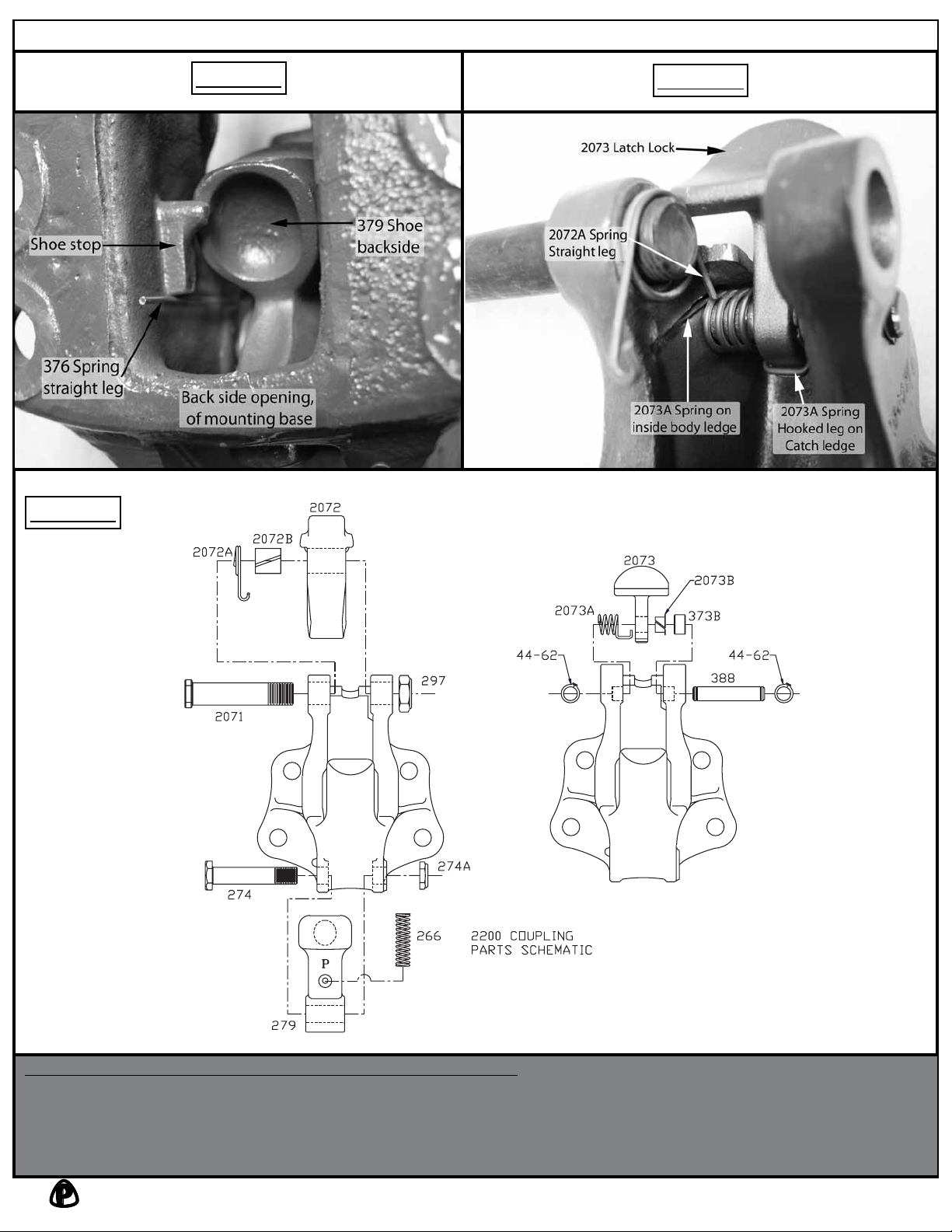
4) Hold the 2073A Spring so that the straight leg is
pointing upward on the left side of the spring and
the hooked leg is on the right. Place the spring
on the left side of the 2073 Latch Lock, aligning
it with the body hole on the left side and the 388
Pin on the right. The straight spring leg should
be along the top ledge, pointing toward you.
5) Rotate the 2073 Latch Lock forward toward you
and capture the hooked end of the spring with
the front part of the catch ledge on the bottom of
the 2073 Latch Lock. Keeping the 2073 Latch
Lock in the forward position, push the 388 Pin
through the 2073A Spring and out the left side of
the coupling body.
6) Closely examine the left side’s interior body
sidewall, adjacent to the 2073A Spring, and
locate the catch ledge running at a 45 degree
angle. This is where the straight leg of the spring
needs to be placed. Using a flat bladed screw
driver, pry the straight leg away from the top
interior ledge of the coupling and rotate it until it
engages with the catch ledge. Please Note: Do
not over stress the 2073A Spring when engaging
either end and also MAKE CERTAIN both the
straight end and hooked end are completely
engaged with the catch site locations (see Image
#4).
7) Rotate the 2073 Latch Lock backwards, to the
opened position. If spring is installed correctly,
smooth increasing spring resistance should be
felt when rotated. If no resistance or binding
is felt, the spring and/or parts are not installed
correctly.
8) Using snap ring pliers, install both 44-62 Snap
Rings into the grooves on the 388 Pin. Verify
that both snap rings are fully seated into their
grooves.
9) Insert the 2071 Bolt from the left side into
the coupling body until the threaded end is
approximately 1/8” past the left side interior
body sidewall. Place the 2072A Spring onto the
protruding 2071 Bolt’s threaded end. The hook
end of the spring should be pointing toward you
and the straight leg facing downward, captured
by the top interior ledge of the coupling (see
Image #4).
10) Place the 2072B Bushing into the hole in the
2072 Latch. With one hand rotate the 2073
Latch Lock back to the opened position and hold.
With the other free hand grasp the 2072 Latch
and lower into position, catching the hooked
end of the spring on the left side sidewall of
the 2072 Latch. Once in position, gently allow
the 2073 Latch Lock to rotate forward, into the
closed position. Now align the 2072 Latch hole
with the 2071 Bolt and slide the bolt to the right
until fully seated. Due to the snug fit caused by
the bushing, it is possible that while pushing the
bolt into place, you may have to twist the bolt
and wiggle the latch to get everything to line up
properly. Do not hammer or tap the bolt through.
This action could possibly damage the bushing.
Secure the bolt with the 297 Locknut on the right
side.
11) Rotate the 2073 Latch Lock to the opened
position and hold. Rotate the 2072 Latch to
the opened position. If the spring is installed
correctly, smooth increasing spring resistance
should be felt when rotated. If no resistance or
binding is felt, the spring and/or parts are not
installed correctly. Reassemble correctly.
12) Once the coupling is assembled it should be
opened and closed several times, testing for
smooth and correct operation. DO NOT use the
coupling if it does not operate properly. Call for
assistance.
13) Use only new fasteners torqued to SAE
specifications when mounting the assembled
coupling to its mounting structure.