ASTRO QAM BOX User manual

Version 01-2013A

Contents
Betriebsanleitung QAM BOX - Version 01-2013ASeite 2
Contents
Device description......................................................................................................................page 03
Guarantee conditions............................................................................................................. ...page 03
Description of performance........................................................................................................page 04
Disposal.....................................................................................................................................page 04
Important!...................................................................................................................................page 04
Installation and connection........................................................................................................page 05
First steps using the web browser interface..............................................................................page 08
Configuring input properties......................................................................................................page 11
Configuring output properties....................................................................................................page 12
NIT Processing..........................................................................................................................page 17
Sorting programmes - the LCN table.........................................................................................page 18
Network settings........................................................................................................................page 19
Checking individual processes - the system logbook................................................................page 20
Expert mode..............................................................................................................................page 21
Software update and configuration files....................................................................................page 25
Troubleshooting........................................................................................................................page 28
Maintenance and repair............................................................................................................page 28
Signal flow diagramme..............................................................................................................page 29
Technical data...........................................................................................................................page 30

Seite 3
Device description
Betriebsanleitung QAM BOX - Version 01-2013A
Device description
/05&: This operating manual was created to provide the most important information
for operating the QAM BOX. We expressly recommend reading this manual before installing
or operating the device.
The ASTRO company confirms the information in this manual to be correct at the time of
printing, but it reserves the right to make changes, without prior notice, to the specifications,
the operation of the device and the operating manual.
The delivery consists of the following parts:
SAT input sockets:
[1] Vertical / Low
[2] Horizontal / Low
[3] Vertical / High
[4] Horizontal / High
SAT output or loop-through sockets:
[5] Horizontal / High
[6] Vertical / High
[7] Horizontal / Low
[8] Vertical / Low
[9] Test point -20 dB
[10] Output socket for RF signal
[11] Earth terminal
[12] Mains power cable
[13] Operating status lamps for the
16 QAM channels
[14] LAN connection socket (RJ 45)
[15] Bus connection socket 1
[16] Bus connection socket 2
QAM BOX
4 screws (M4) with wall plugs (6 mm)
Operating manual
Figure 1: QAM BOX - Terminal assignment
CThe QAM BOX features a CE marking. This confirms thatthe product conforms to the relevant EC direc-
tives and adheres to the requirements specified therein.
Warranty conditions
The general terms and conditions of ASTRO Strobel GmbH apply. You will find these in the current
catalogue or on the Internet under www.astro-kom.de.

Description of performance
Betriebsanleitung QAM BOX - Version 01-2013ASeite 4
Description of performance
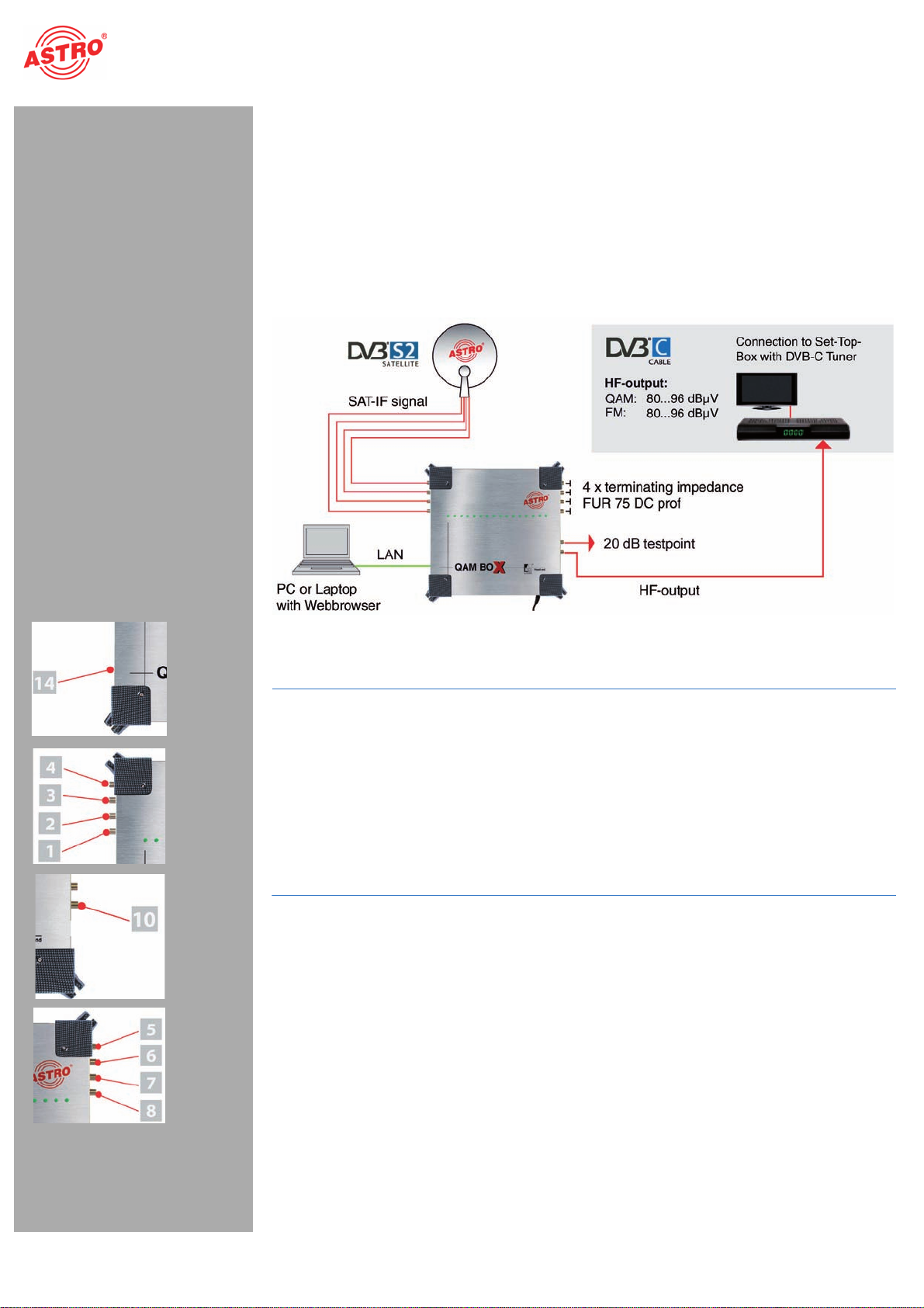
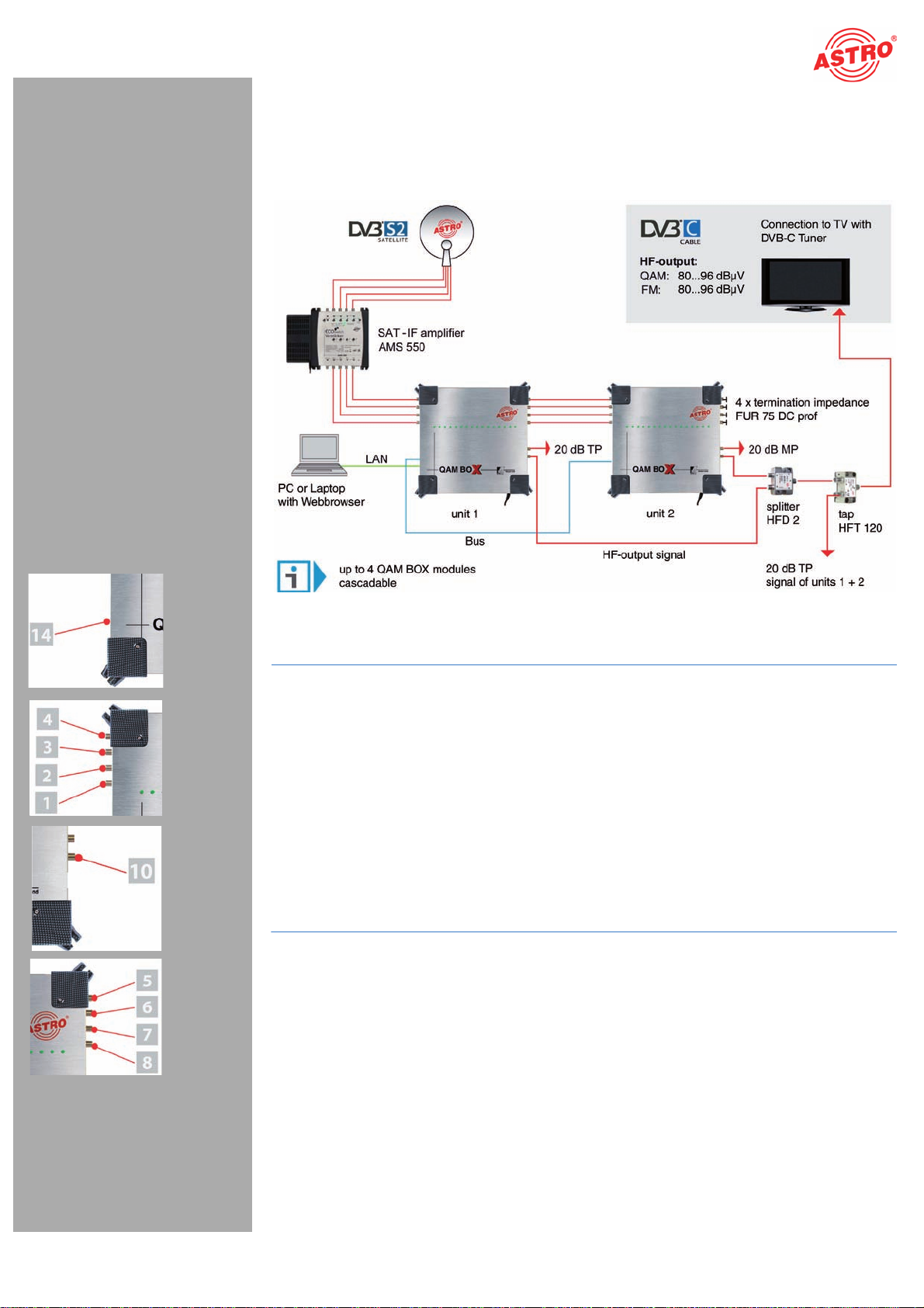
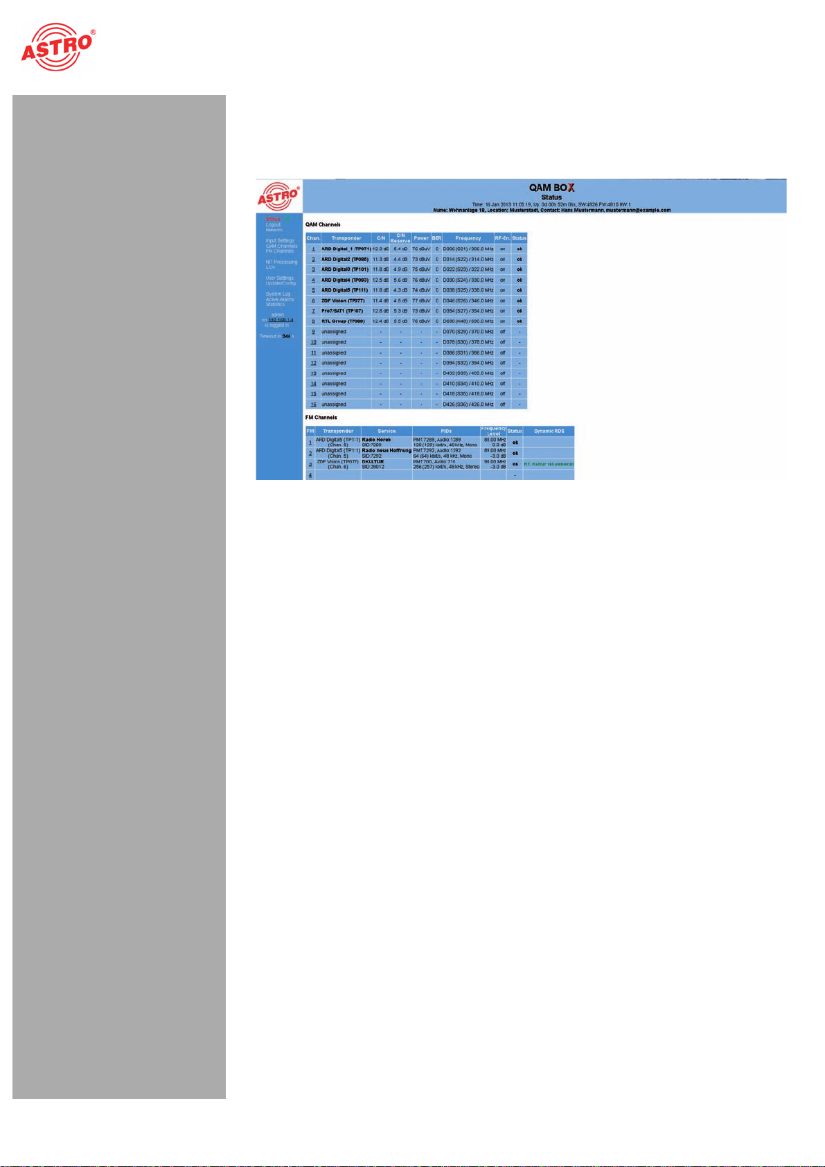
The QAM BOX compact headend is used for converting a DVB-S2 input signal into 16 independent
QAM output channels, as well as 16 FM channels.
To use the device properly, carefully read the following safety and operating instructions.
The QAM BOX compact headend features the following performance characteristics:
4 SAT levels for selection for 16 QAM output channels (DVB-S2)
16 x DVB-S in FM
HDTV-compatible (MPEG-2 and MPEG-4)
Low power consumption (typically 50 W)
Easy to configure using the web browser interface
Disposal
CAll of our packaging material (cardboard boxes, accompanying papers, plastic film and bags) is
completely recyclable. Electronic devices must not be disposed of with household waste, but rather –
according to DIRECTIVE 2002/96/EC OF THE EUROPEAN PARLIAMENT AND OF THE COUNCIL
from January 27, 2003, on waste electrical and electronic equipment – must be properly disposed of.
When it is no longer of use, please bring the device for disposal to one of the public collection points
for this purpose.
ASTRO Strobel is a member of the Elektro system solution for the disposal of packaging materials. Our
contract number is 80395.
Important!
Before using the device, read the operating manually carefully and store it for future reference.
A55&/5*0/: Disconnect the power plug before opening the device!
To avoid any hazardous situations as far as possible, you must adhere to the following:
To operate the device (protection class I), it is essential that it is connected to a mains socket with
protective earth.
The mains plug functions as a mains disconnect and must therefore be accessible and functional
at all times. The device is operational when connected to the mains power.
The device must be connected to a power supply with an earth contact, and should be positioned
close to the mains socket.
The electrical system supplying current to the device, e.g. a house installation, must incorporate
safety devices against excessive current, short-circuiting and earth leakages in accordance with
EN 60950-1.
The device may only be installed and operated by qualified persons (in accordance with EN
60065) or by persons who have been instructed by qualified persons. Maintenance work may only
be carried out by qualified service personnel.
The operating display only shows whether theDC current,which suppliesthe devicecomponents,
has been disconnected. However, operating displays (on the power supply unit or the device) that
are not lit up in no way indicate that the device is completely disconnected from the mains.
The subscriber network must be earthed in accordance with EN 50083-1, and must remain
earthed even when the device is removed. The earth connection on the device (≤4mm2)can also
be used, or the earth connection on the back of the device. Devices within hand's reach must be
integrated into the potential equalisation together.
Operating the device without an earth conductor, without earthing the device or using device
potential equalisation is not permitted!

Seite 5
Installing and connecting
Betriebsanleitung QAM BOX - Version 01-2013A
The device may only be operated and connected in dry rooms. It must not be exposed to spraying
or dripping water, or to similar influences. The device must be assembled on level, non-flammable
materials and substrates.
Operating position: Device vertical, with mains cable outlet at the bottom.
Observe all safety conditions described in the standard IEC 60728-11 when assembling the
device. The device should be operated away from heat radiation and other heat sources. The
device and power supply unit may only be installed in rooms in which the permissible ambient
temperature can be maintained should climatic conditions vary.
To avoid trapped heat, ensure there is good ventilation on all sides (minimum interval of 20 cm to
other objects). Installing the device in recesses or covering the installation location, e.g. with
curtains, is not permitted.
There may be no sources of heat below the device which could have an adverse effect on the
device.
No objects may be placed on the device.
Ventilation openings may not be covered.
If the device is installed in a cabinet, ensure adequate air convection is possible to avoid
exceeding the maximum permitted ambient temperature. The permitted ambient temperatures
specified in the technical data must be complied with.
The device may only be repaired by sending it to ASTRO along with a precise description of the
fault.
Read carefully: EN 50 083 – Part 1, Safety requirements / No service tasks during electrical
storms!
A55&/5*0/: The power supply unit is enclosed in plastic housing. Operating the device
without an intact power supply unit housing, or without the power supply unit housing being
fully intact, is not permitted!
Installing and connecting
Observe all instructions about installation and mains connection described in the section “Important!”.
Start by holding the device in front of the installation location and align it using a spirit level. Then draw
markings for the bore holes through the holes in the feet of the device.
Use a drill bit with a diameter of 6 mm to drill the holes. Insert the wall plugs provided with the device
and use the screws to screw the device in place.
Ensure that the mains voltage, signal sources etc. are properly connected to the device using the
appropriate connections. The local mains voltage must be the same as the supply voltage specified for
operating the device (see the section “Technical Data”).

Installing and connecting
Betriebsanleitung QAM BOX - Version 01-2013ASeite 6
A55&/5*0/: SAT inputs which are not used must each be connected to a terminating
impedance FUR 75 DC prof (required due to the remote feed of galvanic isolation!)
Connecting the QAM BOX to a set-top box with a DVB-C tuner
/05&: Your PC or laptop must be configured accordingly using the network settings in
the operating system! As soon as the QAM BOX is connected to your PC or laptop using your
network connection, you can start with configuration using the web browser interface.
Figure 2: Connecting the QAM BOX
5BTL
1. In order to configure the device using the web browser interface, connect your network, or
laptop/PC, to the RJ 45 socket on the QAM BOX (see position [14] in the figure at the left).
2. Connect the SAT input sockets (see positions [1] - [4] at the left) to the corresponding SAT levels
of the SAT-IF signal using a coaxial cable (see figure 2). When doing so, observe the labelling on
the inputs on the device.
3. Connect the RF output socket (see position [10], left) on the QAM BOX with a set-top box or a TV
set with DVB-C tuner or with several tuners or set-top boxes by interconnecting the corresponding
distributors and splitters.
4. Seal the SAT output sockets (see positions [5] - [8]) with 4 terminal impedances (FUR 75 DC prof).
3FTVMU
The QAM BOX module is now connected, and you can start with the configuration using the web brows-
er interface.

Seite 7
Installing and connecting
Betriebsanleitung QAM BOX - Version 01-2013A
Connecting cascading QAM BOX modules
You can cascade up to 4 QAM BOX modules. An example of a cascade circuit with 2 modules can be
seen in figure 3 below:
Figure 3: connecting several cascading QAM BOX modules
5BTL
1. In order to configure the device using the web browser interface, connect your network, or
laptop/PC, to the RJ 45 socket on the QAM BOX (see position [14] in the figure at the left).
2. Connect the SAT input sockets (see positions [1] - [4] at the left) to the corresponding SAT levels
of the SAT-IF signal using a coaxial cable (see figure 2). When doing so, observe the labelling on
the inputs on the device.
3. Connect the bus connection sockets on the QAM BOX modules to each other.
4. Connect the RF output socket (see position [10], left) on the QAM BOX with set-top boxes or a TV
sets with DVB-C tuners by connecting the corresponding distributors and splitters to each other.
5. Connect each of the SAT output sockets (see positions [5] - [8]) to the SAT input sockets of the
subsequent module.
6. Seal the SAT output sockets of the last QAM BOX module (see positions [5] - [8]) using 4 terminal
impedances (FUR 75 DC prof).
3FTVMU:
The QAM BOX module is now connected, and you can start with the configuration using the web brows-
er interface.
/05& If cascading QAM BOX devices are configured using a switch, then all cascaded
devices must have an IP address of their own.
IP addresses can be changed under the menu item “Network” providing you are logged on as
the administrator.

First steps using the web browser interface
Betriebsanleitung QAM BOX - Version 01-2013ASeite 8
First steps using the web browser interface
General information on the web browser interface layout
The configuration interface is divided into the following sub-areas:
Status line (header): shows general information about the QAM BOX.
SW: Software version
FW: current version of the firmware installed
HW: Hardware version
Up: Duration of connection since booting the system
Time: Date and time
Name, location, contact: corresponds to the settings entered in the configuration area “User”.
Navigation menu (left column): shows the individual configuration areas which can be
selected byclicking the mouse. Adetaileddescriptionofthese areas can be found onthe following
pages of this chapter.
Content area (middle): the respective configuration screen is shown here in accordance with
the menu item selected.
Logging in
To log in, enter the IP address of the QAM BOX (169.254.1.1) in the address line of the browser. You
should then be able to see the input screen for the user authentication (see figure 4, below).
When the device is still in its delivery state, you must use the following log-in data:
User name: “user” or “admin” (input without inverted commas)
Password: astro
HINWEIS: Should you wish to change the IP address, then the settings for the PC also need
to be changed accordingly.
Figure 4: Log in
Once log in is successful, the menu item “log in” changes to “log out”. You will now see the start page
for the QAM BOX with all the relevant system information. The navigation menu and the log-in status
display can be seen on the left-hand side.
The device status is indicated by a green or red circle. If a green circle is displayed, the device is op-
erational. If the circle is red, then a fault has occurred.
Only one user can be logged into the user interface of the QAM BOX at a time. The current user is
displayed in the left-hand column, below the menu.
/05&: For security reasons, you should change the access data valid upon delivery (user
name and password) to prevent unauthorised access!
Logging out
Click on the item “Log out” in the menu on the left.
Figure 5: Logging out
Click on the “Yes” button in the content area to log out of the system as a user.

Seite 9
First steps using the web browser interface
Betriebsanleitung QAM BOX - Version 01-2013A
Changing user data
Click on the menu item “User settings” in the menu at the left to have the corresponding input screen
displayed. You will now see the input screen from figure 6.
Figure 6: User administration
You can create up to four users for the user interface of theQAM BOX. When the device is in its delivery
state, three users exist:
user
admin
controller
The password for all three users is “astro”.
To change the access data for a user account, or to create a new one, enter the required user name in
the input field User name. Then enter the password of your choice in the input field New Password
and confirm it by entering the password again in the input field Retype New Password.
/05&: A password must have at least 5 characters!
To delete a user account, tick the corresponding checkbox Delete in the right-hand column of the ta-
ble.
You can also make the following settings:
Timeout: you can enter a length of time, in minutes, for the automatic log out in this input field.
Should no more activity occur in the user interface, then you will be automatically logged out once
the time entered here has elapsed.
The time remaining until the automatic log out is shown in the left-hand column, under the menu.
Name, location, contact:you can store a name for the system, the location and the contact
data for a person in these input fields.
Language: choose English or German as the menu language here.
Expert mode: activate this option to obtain additional setting options.
*.1035"/5: All changes will only be applied after you have clicked the “Submit” button
below the input screen! Click on the “Reset form” button to delete the values which have been
entered.

First steps using the web browser interface
Betriebsanleitung QAM BOX - Version 01-2013ASeite 10
Monitoring the device status
To display the current settings for the 16 QAM channels and FM stations, click on the entry Status in
the menu at the left. You can now see the overview shown in figure 7:
Figure 7: Status display
QAM channel properties in the display:
Channel: channel number (1 - 16)
Transponder: transponder currently selected
C/N: signal-to-noise ratio
C/N Reserve: reserve until the tuner switches off
Power: input power
BER: bit error rate of the input signal
Frequency: output frequency set for the QAM channel
RF-En: activated or deactivated (on/off)
Status: OK (no errors) or error message
FM station properties in the display:
FM: channel number (1 - 16)
Transponder: transponder currently selected
Service: station selected
PIDs: packet identifier of the station selected
Frequency / level: set output frequency and level reduction
Status: OK (no errors) or error message
Dynamic RDS: current radio data service (if available)

Seite 11
Configuring input properties
Betriebsanleitung QAM BOX - Version 01-2013A
Configuring input properties
Setting SAT inputs
To configure the SAT inputs for the QAM BOX, click on theentry Input settings in the menu at the
left. You can now see the input screen shown in figure 8:
Figure 8: Configuring SAT inputs
Selecting the external unit
Start by selecting the preferred LNC type from the drop-down list. The following options are available:
Quatro-Switch: Select this value if you wish to use a power supply unit with an integrated mult-
iswitch.
Other: Select this value if you wish to use a quatro universal power supply unit.
Once you have selected the preferred value, click on “Submit” to save the selection. Click on the “Reset
form” button to delete the values which were entered beforehand.
Entering input assignment
You can make the settings for the four SAT inputs in the “Input settings” table (see figure 9, below).
Figure 9: Input settings
The following setting options can be selected for each input:
Satellite: selection of the satellite for reception from the drop-down list
Polarisation: Selection of the polarisation level from the drop-down list
Voltage (18 V): LNC voltage supply: for inputs 1 and 3 only; activate this setting by clicking
the radio button “on”; deactivate this setting by clicking the radio button “off”.
Voltage (14 V): LNC voltage supply: for inputs 2 and 4 only; activate this setting by clicking
the radio button “on”; deactivate this setting by clicking the radio button “off”.

Configuring output properties
Betriebsanleitung QAM BOX - Version 01-2013ASeite 12
Frequency (22 kHz): 22 kHz generator: activate this setting by clicking the radio button “on”;
deactivate this setting by clicking the radio button “off”.
Status: shows the operating status; when functioning properly, “OK” is displayed.
Once you have selected the preferred option, click on “Submit” to save the selection. Click on the “Re-
set form” button to delete the values which were entered beforehand.
/05&: If you selected “Quatro-switch” as a value in the “Configuration of the external
unit” table, then only the drop-down list for the satellite for input 1 is available for selection.
Configuring output properties
Setting QAM channels
To configure the QAM channels, click on the entry QAM Channels in the menu at the left. You can
now see the input screen shown in figure 10:
Figure 10: Configuring QAM channels
You can make the settings for the 16 QAM channels in the “QAM Channels” table (see figure 11, be-
low).
Figure 11: Setting output properties

Seite 13
Configuring output properties
Betriebsanleitung QAM BOX - Version 01-2013A
The following setting options can be selected for each channel:
Transponder: selection of a transponder (frequency, input, TS-ID, ON-ID) from the drop-down
list
C/N: display of the signal-noise ratio
Channel-Frequency: selection of a channel from the drop-down list; you can select channel
settings from the channel list provided here. If a value is selected from the drop-down list, then the
input screen for the output frequency remains inactive in the detailed view and the corresponding
channel centre frequency is displayed. If the option “manual” is selected, then you have the option
of entering a channel centre frequency.
Modulation: setting the modulation; the options “64 QAM” and “256 QAM” are available for
selection.
Level: you can set the level of the output signal here. Enter the preferred signal level in dB in the
input field. The input can be made in increments of 0.1 dB. The range which can be set depends
onthe type ofmodulation selected (QAM 64up to +3dB,QAM 256upto +3dB).If aninadmissably
high value is set, an error message appears. As soon as the error message is confirmed by
clicking the “OK” button, the maximum value will be entered. This will only be saved once the
“Submit” button under the table has been clicked.
RF ENABLE: Activate this output by clicking the radio button “on”; deactivate this setting by
clicking the radio button “off”.
Status: shows the operating status; when functioning properly, “OK” is displayed.
Onceyou haveselectedthe preferred option,clickon “Submit”to save theselection.Click onthe“Reset
form” button to delete the values which were entered beforehand.
You can have a detailed view of the settings for a QAM channel displayed by clicking on the channel
number in the first column of the “QAM channels” table. You will then see the following overview:
Figure 12: QAM channels - Detailed view
SAT input properties
The “SAT Input Selection” table allows you to set the following properties manually, provided a manual
selection was made beforehand:
Frequency: enter the frequency in MHz in the input field.
Symbol rate: you can modify the input symbol rate here by entering the required value (in
kBaud) in the input field.
TS-ID: enter the required transport stream ID (decimal) in the input field.
ON-ID: enter the required ON-ID (decimal) in the input field.
Save the changes by clicking on the “Submit” button. Delete any settings entered previously by clicking
on the “Reset Form” button.

Configuring output properties
Betriebsanleitung QAM BOX - Version 01-2013ASeite 14
Output properties
You can enter the following properties manually in the “Output Settings” table:
Modulation: select the required modulation from the drop-down list; the options available are
“64 QAM”, “256 QAM” (see the “QAM channels” table further above).
Symbol rate: you can modify the output symbol rate here by entering the required value (in
kBaud) in the input field.
Apply settings to all channels:tick the checkboxif you wish to applythe values entered
to all the QAM channels.
Save the changes by clicking on the “Submit” button. Delete any settings entered previously by clicking
on the “Reset Form” button.
Setting FM channels
To configure the FM channels, click on the entry FM Channels in the menu at the left. You can now
see the input screen shown in figure 13:
Figure 13: Setting FM channels
You can make the settings for the 16 radio stations in the “FM Channels” table (see figure 14, below).
Figure 14: Setting FM channels (excerpt)

Seite 15
Configuring output properties
Betriebsanleitung QAM BOX - Version 01-2013A
The following setting options can be selected for each channel:
Radio-Service: select a radio service from the drop-down list.
Frequency: enter the frequency in MHz in the input field.
Level: enter the preferred signal level in dB in the input field.
RF ENABLE: activate this output by clicking the radio button “on”; deactivate this setting by
clicking the radio button “off”.
Status: shows the operating status; when functioning properly, “OK” is displayed.
Onceyou haveselectedthe preferred option,clickon “Submit”to save theselection.Click onthe“Reset
Form” button to delete the values which were entered beforehand.
You can have a detailed view of the settings for an FM channel displayed by clicking on the channel
number in the first column of the “FM Channels” table. You will then see the following overview:
Figure 15: FM channels - Detailed view
Service settings
In the “Service Settings” overview, you can enter detailed settings for a radio station. The following, spe-
cific options are available:
Transport Stream: select the required transport stream here.
SID: enter the required SID in the input field.
Audio: enter the required PID in the input field (the service ID must be set to 0).
RDS: enter the required PID in the input field.
Onceyou haveselectedthe preferred option,clickon “Submit”to save theselection.Click onthe“Reset
Form” button to delete the values which were entered beforehand.

Configuring output properties
Betriebsanleitung QAM BOX - Version 01-2013ASeite 16
Modulation
Figure 16: Modulation settings
In the “Modulation” overview, you can set the following modulation properties:
Audio: enter the preferred audio hub (dB) in the input field.
Radio Data System (RDS): activate RDS by clicking the radio button “on”; deactivate the
output by clicking the radio button “off”.
Programme Service Name (PS): activate dynamic generation of the channel name when the
PS information is provided in the transport stream. To do so, click on the radio button “dynamic”.
Activate static generation if no PS is provided in the transport stream. To do so, click on the radio
button “static”.
Then enter the information to be displayed in alternation (up to 8 characters) in the individual input
fields. In the input field “PS change time”, you can enter a time value in seconds, after which the
respective display of information will change.
If PS data is provided in the transport stream, then the transport stream data will be processed
with priority.
Programme Identification (PI): if the PI is transmitted by the station, then this will also
be transmitted on the output side if the radio button “dynamic” is activated here.
If you activate the radio button “static” and enter a station ID in the adjacent field, then this setting
will be transmitted until a PI is provided by the station.
Programme Type (PTY): set the transmission of the channel type ID here.
Activate dynamic generation of the channel type ID when the information is provided in the trans-
port stream. To do so, click on the radio button “dynamic”.
Activate static generation if no channel type ID is provided in the transport stream. To do so, click
on the radio button “static” and enter a station ID in the adjacent input field.
If data for the station type ID is provided in the transport stream and the radio button “dynamic”
has been activated at the same time, then the transport stream data will be processed with priority
in this case as well.
Traffic Programme Identification (TP):activate transmission ofthe trafficprogramme
ID by activating the checkbox “on”.
Music Speech Switch (MS): if available on the station side, an ID can be transmitted which
provides information about whether speech or music is being broadcast. Some terminal devices
can adapt the volume control automatically using this ID.
Activate dynamic generation of the music ID when the information is provided in the transport
stream. To do so, click on the radio button “dynamic”.
Activate static generation if no music ID is provided in the transport stream. To do this, click either
the radio button “speech” or “music”.
If data for music identification is provided in the transport stream, then the transport stream data
will be processed with priority.

Seite 17
NIT Processing
Betriebsanleitung QAM BOX - Version 01-2013A
Radiotext (RT): if provided by the station, then radio text can be transmitted.
Activate dynamic generation of the radio text when the information is provided in the transport
stream. To do so, click on the radio button “dynamic”.
Activate static generation if no radio text is provided in the transport stream. To do so, click on the
radio button “static”. Enter the preferred radio text in the input field next to it. As soon as radio text
data is transmitted by the transport stream, it will be given priority in the display.
Clock Time and Date (CT): activate the radio button “on” to allow the current time to be
displayed in the reception device. Activate the radio button “off” if the current time should not be
displayed in the reception device.
Onceyou haveselectedthe preferred option,clickon “Submit”to save theselection.Click onthe“Reset
Form” button to delete the values which were entered beforehand.
NIT Processing
NIT Processing
To display the input screen “NIT Processing”, click on the entry “NIT Processing” in the menu at the left.
You will see the following table:
Figure 17: NIT Processing
The interface for NIT processing is divided into the following sub-areas:
Edit network information
Enter the network ID and the network name in the respective input field here.
Onceyou haveselectedthe preferred option,clickon “Submit”to save theselection.Click onthe“Reset
Form” button to delete the values which were entered beforehand.

Sorting programmes - the LCN table
Betriebsanleitung QAM BOX - Version 01-2013ASeite 18
Add external transport streams
Should you wish to integrate other devices, made by other manufacturers, in your system in addition
to the QAM BOX, then you can add the transport stream for these devices manually. The following op-
tions are provided here:
TS-ID: enter the transport stream ID of the device in the input field.
ON-ID: enter the ON-ID in the input field.
Frequency: enter the frequency in MHz in the input field.
Modulation: select the required modulation from the drop-down list; the options available are
“64 QAM”, “256 QAM”.
Symbol Rate: enter the symbol rate in MS/s in the input field.
Click on the “Add” button one you have made all the settings. The transport stream will then be added
to the NIT (see table “NIT”).
NIT
The NIT is automatically generated using the transponders which have been set. If several QAM BOX
modules are being cascaded using the bus connection, then the NIT will be displayed for all cascaded
modules. In the “Info” column, “local” will no longer be displayed, but rather the IP address for the re-
spective module.
If external transport streams are added to the NIT, then a checkbox will be displayed in the “Remove
(external TS)” column for these streams. Tick this box if you wish to remove an external transport
stream from the NIT.
Once you have selected the preferred option, click on “Submit” to save the selection. Click on the “Re-
set Form” button to delete the values which were entered beforehand.
Sorting programmes - the LCN table
If receivers with LCN support are being used in your system, you can define the station sequence with
the help of the input screen “LCN table”. To do so, start by clicking on the entry “LCN” in the menu at
the left. You will see the following table:
Figure 17: LCN table
Service selection for creation of the LCN table
In the left column, enter the LCN digit which you wish to add to the LCN table. Select the preferred serv-
ice from the drop-down list in the right column.
Once you have selected all services which you wish to add to the LCN table, click on the “Add selected
services to LCN Table” button.
/05&: When cascading QAM BOX modules which are already connected by bus, the
service information for all devices will be displayed and can be selected.

Seite 19
Network settings
Betriebsanleitung QAM BOX - Version 01-2013A
LCN table
Use the arrow buttons in the “Sort” column to move individual services further up or down in the list.
Onceyou haveselectedthe preferred option,clickon “Submit”to save theselection.Click onthe“Reset
Form” button to delete the values which were entered beforehand.
Network settings
To have the network settings displayed, click on “Network” in the menu at the left. You will then see the
following overview:
Figure 19: Network settings
You can check or set the following properties in detail:
IP Interface settings
MAC: shows the MAC address.
Mode: displays the available bandwidth (100 Mbit/s).
Address: shows the IP address (can only be edited when logged in as Admin).
Subnet: shows the subnet mask (can only be edited when logged in as Admin).
Broadcast: broadcast address of the subnet. This may not be used as the IP address of the
device.
Gateway: interface to the internet (e.g. IP address of the router).
DNS: name server; input required when e.g. updates are to be deployed using the FTP server
(“ftp.astro-firmware.de”).
/05&: Input fields shown in grey can only be edited when you are logged in as Admin-
istrator.

Checking individual processes - the system log
Betriebsanleitung QAM BOX - Version 01-2013ASeite 20
Time setting
Select a station as a time source from the drop-down list.
Once you have selected the preferred option, click on “Submit” to save the selection. Click on the “Re-
set Form” button to delete the values which were entered beforehand.
Default settings / reboot
To reset the system to the factory default settings, click the “Load factory settings” button.
/05&: Once you have clicked the “Load factory settings” button, all settings made up
to this point will be deleted, except for the network and user settings!
Click on “Restart QAM BOX” to perform a reboot.
Checking individual processes - the system log
To have the system log displayed, click on “System Log” in the menu at the left. You will then see the
following overview:
Figure 20: System log
You can check, or set, the following properties in detail:
System log settings
You can activate or deactivate the filter used for displaying the system log entries here. To have mes-
sages
from a corresponding category displayed, tick the checkbox allocated to the category.
This manual suits for next models
1
Table of contents
Other ASTRO TV Tuner manuals