ASTUTE Astute140 Meter User manual

©Astute Medical, Inc. 2017 PN 300153 Rev G 2017/01/16
ASTUTE14 0 ® METER
STUTE
14 0
M
ETER
USER MANUAL

©Astute Medical, Inc. 2017 PN 300153 Rev G 2017/01/16
Astute140®Meter
2
CONTACT INFORMATION:
Astute Medical, Inc.
3550 General Atomics Ct.
Building 2
San Diego, CA 92121 USA
Phone: +1 (855) 317-2788 (Monday thru Friday, 8am – 5pm PST)
Fax: +1 (858) 332-0690
Email: technicalsupport@astutemedical.com
Website: www.astutemedical.com
Manufactured for Astute Medical, Inc.
3550 General Atomics Ct.
Building 2
San Diego, CA 92121
USA

©Astute Medical, Inc. 2017 PN 300153 Rev G 2017/01/16
Astute140®Meter
3
Table of Contents
Introduction ............................................................................................................................................... 5
Intended Use ........................................................................................................................................... 5
Principles of Operation ........................................................................................................................ 5
Astute140®Meter Kit Contents ....................................................................................................... 6
Materials Required But Not Provided ............................................................................................ 7
Optional Accessories ........................................................................................................................... 7
Contacting Astute Medical, Inc. (Technical Support) .............................................................. 7
Product Specications ........................................................................................................................ 8
Warnings, Hazards, Precautions and Limitations .................................................................... 9
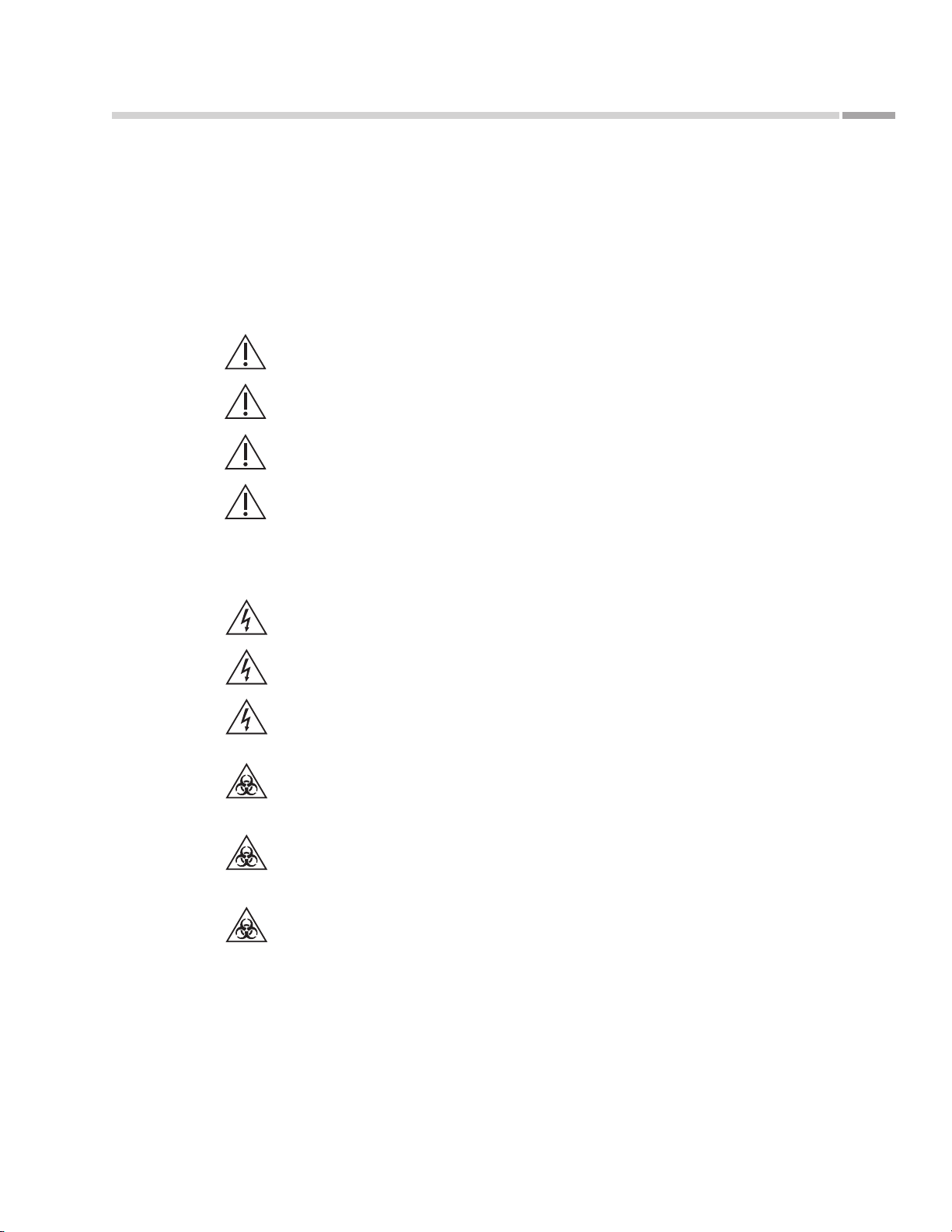
Safety Symbols ................................................................................................................................ 9
Safety Information .......................................................................................................................... 9
FCC Testing ...................................................................................................................................... 10
Electromagnetic Capability (EMC) .......................................................................................... 10
Limitations ......................................................................................................................................... 11
Astute140®Meter Features .............................................................................................................. 12
User Types .............................................................................................................................................. 15
Operator ............................................................................................................................................. 15
Supervisor ......................................................................................................................................... 16
Installation ................................................................................................................................................ 17
AC Power Supply .................................................................................................................................. 17
Installation and Replacement of Batteries ................................................................................ 18
Installation and Replacement of Paper ....................................................................................... 21
Powering On the Astute140®Meter ............................................................................................ 22
Supervisor Instructions: Conguration and Settings ........................................................... 23
Adding the First Supervisor User ........................................................................................... 23
Setting or Changing Time .......................................................................................................... 26
Setting or Changing Date .......................................................................................................... 27
Setting or Changing the Language ....................................................................................... 28
Updating System Software ....................................................................................................... 29
Updating Astute140®Meter Languages ............................................................................. 29
Operator Registering Permissions ........................................................................................ 29
Quality Control Settings .............................................................................................................. 31
LIS Settings ..................................................................................................................................... 32
Network Settings .......................................................................................................................... 34
PC Mode ........................................................................................................................................... 36
Printer Settings .............................................................................................................................. 37
Managing Users ............................................................................................................................ 38
Astute140®Meter Information ................................................................................................ 40
Error Log ........................................................................................................................................... 42

©Astute Medical, Inc. 2017 PN 300153 Rev G 2017/01/16
Astute140®Meter
4
Table of Contents (Continued)
Astute140®Meter Operation .................................................................................................... 45
Startup ..................................................................................................................................................... 45
Powering On the Astute140®Meter ...................................................................................... 45
Logging In ........................................................................................................................................ 46
Non-Permanent Settings .......................................................................................................... 46
RFID Cards for Device and Lot Registration ............................................................................ 48
Astute140®EQC Device Registration ......................................................................................... 48
Astute140®Electronic Quality Control (EQC) .......................................................................... 50
Test Lot Registration .......................................................................................................................... 52
Liquid Control Lot Registration ..................................................................................................... 54
External Liquid Quality Control (LQC) ........................................................................................ 56
Calibration Verication Testing .................................................................................................... 60
Testing a Patient Sample ................................................................................................................. 62
Review and Management of Test Results ................................................................................ 65
Patient Results ............................................................................................................................... 65
LQC Results ..................................................................................................................................... 67
EQC Results .................................................................................................................................... 68
Calibration Verication Results .............................................................................................. 69
Send Results to LIS ...................................................................................................................... 70
Shutdown ............................................................................................................................................... 70
Maintenance and Troubleshooting ......................................................................................... 71
Cleaning and Decontamination ...................................................................................................... 71
Replacing the Paper ........................................................................................................................... 72
Replacing the Batteries ..................................................................................................................... 72
Disposing of the Batteries ............................................................................................................... 72
Disposing of the Astute140®Meter ............................................................................................. 72
Labels and Symbols ........................................................................................................................... 73
Troubleshooting Tips ......................................................................................................................... 74
Error Messages .................................................................................................................................... 76
End User License Agreement .................................................................................................... 89
Glossary of Terms (Listed Alphabetically) ....................................................................... 90
Index ............................................................................................................................................................ 92
Appendix .................................................................................................................................................. 94
Main Menu Structure ........................................................................................................................ 94
Review Data Menu Structure ......................................................................................................... 95
Operator Menu Structure ................................................................................................................ 96
Supervisor Menu Structure ............................................................................................................. 97

©Astute Medical, Inc. 2017 PN 300153 Rev G 2017/01/16
Astute140®Meter
5
Introduction
Intended Use
The Astute Medical NephroCheCk®Test System is intended to be used in conjunction
with clinical evaluation in patients who currently have or have had within the past 24
hours acute cardiovascular and or respiratory compromise and are ICU patients as an aid
in the risk assessment for moderate or severe acute kidney injury (AKI) within 12 hours of
patient assessment. The NephroCheCk®Test System is intended to be used in patients 21
years of age or older.
Please read these instructions carefully before using the Astute140®Meter.
Please refer to the assay-speci c Product Insert for detailed test information.
Principles of Operation
The Astute140® Meter uses an optical system to measure the fl uorescent signal
generated from the test sample in the NephroCheCk®Test cartridge. After the addition
of the sample, the NephroCheCk®Test cartridge containing the patient sample is
inserted into the Astute140® Meter. The meter then converts the fl uorescent signal
from each of the two immunoassays (TIMP-2 and IGFBP-7) into a concentration and
then multiplies these concentrations into a single numerical test result and displays
this result to the user. The results from the individual biomarkers are not displayed—
only the single numerical test result is displayed. Multiple quality control procedures
are performed to ensure that the test results are accurate (See “Astute140®Electronic
Quality Control (EQC)” on p. 50 and “External Liquid Quality Control (LQC)” on p. 56
for details).
Results of the test are displayed on the Astute140®Meter’s LCD screen and may be
printed using the meter’s internal printer, or electronically transmitted to a connected
laboratory information system (LIS).

©Astute Medical, Inc. 2017 PN 300153 Rev G 2017/01/16
Astute140®Meter
6
Introduction
Astute140®Meter Kit Contents
Inspect the shipping container for obvious shipping damage prior to opening. Unpack
the shipping container and inspect the contents for damage. Following are components
included in the Astute140®Meter Kit along with part numbers for items that can be
ordered separately:
Astute140®Meter Kit Component Part Number for Re-ordering
Astute140®Meter (1)
Power adapter pack (includes AC power cord, switching
power supply and country specic adapter) (1)
USB cable (1)
Astute140®Electronic Quality Control (EQC) Device
with RFID card* 400016
Astute140®User Manual (1)
Printer paper rolls (2) 100000
AA batteries (4) (1)
(1) This component is only available as part of the Astute140®Meter Kit. Additional
Astute140®Meter Kits can be ordered using Part Number 500017.
*Packaged and shipped in a separate box.
If the shipping container or its contents are damaged, or if any components are missing,
contact Astute Technical Support (See “Contacting Astute Medical, Inc.” on p. 7 for
contact information).
To avoid damaging the Astute140®Meter, DO NOT use any power adapter
other than the one provided.
Batteries are not intended to be used as the main power source for operation
of the Astute140®Meter and should only be used as a backup power source
if there is no electrical output available (See “Installation and Replacement of
Batteries” on p. 18 for further details).

©Astute Medical, Inc. 2017 PN 300153 Rev G 2017/01/16
Astute140®Meter
7
Introduction
Materials Required But Not Provided
The following materials are required for testing patient samples and may be purchased
and shipped separately from Astute Medical, Inc:
NephroCheCk®Test Kits (PN: 500011)
NephroCheCk®Liquid Control Kits (PN: 500013)
For a list of approved tests and corresponding liquid controls for use with the
Astute140®Meter, go to www.astutemedical.com or consult your Astute Medical, Inc.
sales representative.
Optional Accessories
Optional accessories that may be used with the Astute140®Meter include the
NephroCheCk® Calibration Verication Kit, an external barcode reader and an external
keyboard. A numeric or alphanumeric barcode reader with a PS2 interface will work with
the Astute140®Meter, such as the DataLogic DLC6065-M1, Opticon OPR-2001, or the
Honeywell 3800G (others have not been tested).
A keyboard with a PS2 interface will work with the Astute140®Meter. Wireless
keyboards are not compatible with the Astute140®Meter.
Contacting Astute Technical Support
Installation, service and maintenance are the responsibility of the End User. For
technical support, please contact Astute Technical Support at:
Astute Medical, Inc.
3550 General Atomics Ct.
Building 2
San Diego, CA 92121 USA
Phone: +1 (855) 317-2788 (Monday thru Friday, 8am – 5pm PST)
Fax: +1 (858) 332-0690
Email: technicalsupport@astutemedical.com
Website: www.astutemedical.com

©Astute Medical, Inc. 2017 PN 300153 Rev G 2017/01/16
Astute140®Meter
8
Introduction
Product Specications
Astute140®Meter Information
Product Number: 500017
Dimensions: 9.8" Length x 6.8" Width x 4.6" Height
Weight: 2.6 lbs. (without batteries or paper roll)
Power Requirements
AC Power Supply Output Voltage: 6 V DC and 4.16 A
AC Power Supply Input Voltage/
Voltage Range: 100V – 240 V, 47Hz – 63 Hz
Battery Operation: 4 x LR6 — AA batteries
Operating Environment
Temperature: 59°F – 86°F
Humidity: 30% – 80% rH, non-condensing at 59°F operating temperature
15% – 80% rH, non-condensing at 86°F
Storage Environment
Temperature: -4°F to 140°F
Humidity: 20% – 85% rH, non-condensing

©Astute Medical, Inc. 2017 PN 300153 Rev G 2017/01/16
Astute140®Meter
9
Introduction
Warnings, Hazards, Precautions, and Limitations
Refer to the Symbols Glossary for more information
Safety Information
Operate the Astute140®Meter on a level, dry surface.
Do not move the Astute140®Meter while a test is running.
Do not drop the Astute140®Meter.
The Astute140®Meter is designed to provide safe and reliable operation
when used according to this User Manual. If the meter is used in a manner not
specied in the User Manual, the protection provided by the equipment will be
impaired.
Use only the AC power adapter supplied with the Astute140®Meter.
Do not immerse the Astute140®Meter in water or any other liquids.
Unplug the AC power adapter from the power supply before cleaning.
Handle and dispose of test cartridges and patient specimens in accordance
with federal, state, and local requirements regarding biohazardous materials.
Handle the Astute140®Meter in accordance with federal, state and local
requirements regarding biohazardous materials.
Due to potentially infectious nature of the samples used with the Astute140®
Meter, users should wear gloves.

©Astute Medical, Inc. 2017 PN 300153 Rev G 2017/01/16
Astute140®Meter
10
Introduction
FCC Testing
This device complies with Part 15 of the FCC Rules. Operation is subject to the
following two conditions:
1. This device may not cause harmful interference, and
2. This device must accept any interference received, including interference
that may cause undesired operation.
Changes or modications not expressly approved by the party responsible for
compliance could void the user’s authority to operate the equipment.
NOTE: This equipment has been tested and found to comply with the limits for a
Class A digital device, pursuant to part 15 of the FCC Rules. These limits are designed
to provide reasonable protection against harmful interference when the equipment
is operated in a commercial environment. This equipment generates, uses, and can
radiate radio frequency energy and, if not installed and used in accordance with
the instruction manual, may cause harmful interference to radio communications.
Operation of this equipment in a residential area is likely to cause harmful interference
in which case the user will be required to correct the interference at his own expense.
Electromagnetic Capability (EMC)
The electromagnetic environment should be evaluated prior to operation of the
Meter. The Meter generates radio frequency (RF) energy. Do not use this device
in close proximity to sources of strong electromagnetic radiation (e.g. unshielded
intentional RF sources), as these may interfere with proper operation.
Any equipment connected to data ports must be certied to EC61010. If any
equipment is connected that is not recommended it must comply with this
standard. For questions or additional information, please contact Astute Technical
Support (See “Contacting Astute Medical, Inc.” on p. 7 for contact information).
The Astute140®Meter complies with the emission and immunity requirements
described in IEC 61326-2-6.

©Astute Medical, Inc. 2017 PN 300153 Rev G 2017/01/16
Astute140®Meter
11
Introduction
Limitations
The Astute140®Meter does not contain a “batch mode” function. The Astute140®
Meter times the incubation period for the test, and only one test can be run at a time;
therefore, each NephroCheCk®Test cartridge must be run immediately after being
loaded with the patient sample or liquid control. The time delay in testing that would
result from loading more than one cartridge at a time may lead to inaccurate test
results.

©Astute Medical, Inc. 2017 PN 300153 Rev G 2017/01/16
Astute140®Meter
12
Introduction
Astute140®Meter Features
13
12
11
1
2
3
4
5
6
7
8
9
10
Feature Function
1Printer Cover Covers the printer
2LCD Display User interface—displays screens for navigating, entering data, and reviewing data
3Paper Feed Key Advances the paper roll
4Eject Key Opens the drawer
5Main Menu Key Used to return to the Main Menu
6Navigation Keys Used to navigate up, down, left, and right within menu screens
7Left Soft Key Used to select the menu option displayed above the key
8Right Soft Key Used to select the menu option displayed above the key
9Numeric Keypad Used to enter numerical values into menus and screens
10 Decimal Point Used to add decimal points to numerical values
11 Backspace Key Deletes the character to the left of the cursor
12 Drawer Used to insert a NephroCheCk®Test cartridge and the Electronic Quality Control (EQC)
device into the Astute140®Meter
13 Battery Cover Covers the battery compartment
Figure 1.
Astute140®Meter

©Astute Medical, Inc. 2017 PN 300153 Rev G 2017/01/16
Astute140®Meter
13
Introduction
Astute140®Meter Features (Continued)
123
4
5
Feature Function
1PS/2 Port Used to connect the optional external barcode reader or keyboard to the
Astute140®Meter
2Ethernet Port Used to connect the Astute140®Meter to an LIS or to a computer network to
download software
3AC Power Adapter Port Used to connect the AC power adapter to the Astute140®Meter
4USB Port Used to connect the Astute140®Meter to a computer to download new software
5On/Off Switch Used to power the Astute140®Meter on and off
Figure 2.
Astute140®
Meter — back

©Astute Medical, Inc. 2017 PN 300153 Rev G 2017/01/16
Astute140®Meter
14
Introduction
Astute140®Meter Features (Continued)
2
1
3
Feature Function
1Battery Cover Covers the battery compartment
2Serial Number Unique number used to identify the Astute140®Meter
3In Vitro Diagnostic Regulatory labels and symbols used to provide information about the
device labels Astute140®Meter and its proper use (See “Labels and Symbols” on p. 73
and symbols for denitions)
Figure 3.
Astute140®
Meter — bottom

©Astute Medical, Inc. 2017 PN 300153 Rev G 2017/01/16
Astute140®Meter
15
Introduction
Astute140®Meter Features (Continued)
1 2 3
4 5 6
All Astute140®Meter functions are grouped under six icons found on the Main Menu
(For menu structures, see the Appendix):
Feature Function
1Run Patient Select to run patient tests
2Run LQC Select to run high and low liquid controls
3Review Data Select to manage patient, LQC and EQC test results
4Run EQC Select to run EQC
5Operator Select to manage (register or delete) test lots, liquid control lots, and EQC devices;
temporarily change non-permanent settings, and view error logs
6Supervisor Select to set/change general settings, manage users, obtain Astute140®Meter
information, or view error logs
User Types
There are two types of users dened for the Astute140®Meter, Supervisor and
Operator. Supervisors and Operators are permitted to perform dierent functions, as
described below.
Operator
Users logged in as Operators may perform the following functions:
Power the Astute140® Meter on/o
Run electronic quality control (EQC)
Figure 4.
Main Menu screen

©Astute Medical, Inc. 2017 PN 300153 Rev G 2017/01/16
Astute140®Meter
16
Introduction
Run liquid quality control (LQC)
Run Calibration Veri cation
Test patient samples
Review and print data (Patient test results, QC test results)
View error log
Operators may perform the following functions only if a Supervisor grants permission
in the default settings:
Manage (register/delete/print) test lots
Manage (register/delete/print) LQC lots
Manage (register/delete/print) EQC devices
The Operator may change the following settings temporarily while using the
Astute140®Meter; the settings will return to the default settings programmed by the
Supervisor when the meter is switched o or the Operator is logged out:
Date format
Time format
Language
Beeper (On/O )
Supervisor
Users logged in as Supervisors may perform all of the Operator functions and the
following additional functions:
Set or change all default system settings (Time, Date, Language, Log On Setup,
registering lot/control permissions, QC settings)
Set or change LIS settings
Set PC Mode (On/O )
Set or change network settings
Set or change print headers
Manage Users (change/add/delete)
View Astute140® Meter information (hardware/ rmware/bootware/serial
number/IP address)

©Astute Medical, Inc. 2017 PN 300153 Rev G 2017/01/16
Astute140®Meter
17
Installation
AC Power Supply
The Astute140®Meter is generally meant to be powered by plugging the AC power
adapter into a power source; however, power may be supplied temporarily by four
AA batteries when an electrical power source is unavailable (See “Installation and
Replacement of Batteries” on p. 18). NOTE: If the AC power adapter is in use and the
electrical power fails or the power adapter becomes disconnected, the meter will power
o even if batteries are installed in the Astute140®Meter.
To connect the AC power adapter:
1. Locate the AC power adapter pack containing the AC power cord, the switching
power supply, and the country-speci c adapter, then connect them as shown:
2. Insert the end of the country-speci c adapter into a power source.
Figure 5.
Connecting power cords

©Astute Medical, Inc. 2017 PN 300153 Rev G 2017/01/16
Astute140®Meter
18
Installation
3. Insert the cylindrical end of the switching power adapter into the AC power
adapter port on the back of the Astute140®Meter.
To avoid damage to the Astute140®Meter from a potential power surge, always
plug the AC power adapter into the electrical power source prior to connecting it
to the meter. When removing power, disconnect the AC power adapter from the
Astute140®Meter prior to unplugging it from the electrical power source.
Installation and Replacement of Batteries
The Astute140®Meter is generally meant to be powered by plugging the AC power
adapter into an electrical power source (See “AC Power Supply” on p. 17); however,
power may be supplied for a limited period of time by four AA batteries when an
electrical power source is unavailable (for example, in the event of electricity failure
or if the meter must be operated in a location where there is no electric output).
NOTE: If the AC power adapter is in use and the electrical power fails or the power
adapter becomes disconnected, the meter will power o even if batteries are installed in
the Astute140®Meter.
When using alkaline or lithium batteries under a temperature operating range of
20oto 25oC, the Astute140®Meter will allow approximately 10 user tests to be
performed before requiring battery replacement.
Figure 6.
Connecting AC power
adapter to Astute140®
Meter

©Astute Medical, Inc. 2017 PN 300153 Rev G 2017/01/16
Astute140®Meter
19
Installation
The Astute140®Meter includes a battery strength indicator.
The batteries should be changed when the battery strength indicator is displayed as
empty and blinking.
When the battery strength indicator is displayed as empty and blinking, the Astute140®
Meter can run one additional test within one hour under the same operating conditions
before the batteries will need to be replaced.
To install four AA batteries into the Astute140®Meter or to change the batteries:
1. Press the key to the left of the LCD display to open the Astute140®Meter
drawer and ensure there is not a cartridge in the meter.
2. Power o the Astute140®Meter.
Figure 7.
Battery strength
indicator — full
Figure 8.
Battery strength
indicator — empty and
blinking

©Astute Medical, Inc. 2017 PN 300153 Rev G 2017/01/16
Astute140®Meter
20
Installation
3. Gently turn the Astute140®Meter over so the bottom is facing up and place it on a
fl at surface.
4. Open the battery cover by pressing your thumb rmly on the center of the battery
cover and sliding it in the direction shown below:
5. If replacing the batteries, remove the old batteries and properly discard them
(See “Disposing of the Batteries” on p. 72).
Figure 9.
Astute140®Meter —
bottom facing up
Figure 10.
Removing battery cover
Other manuals for Astute140 Meter
1
Table of contents
Other ASTUTE Medical Equipment manuals