Asus OC STATION User manual

English
Français
Deutsh
Italiano
Español
Português
Русский
简体中文
日本語
한국어
Quick Installation Guide
Second Edition
May 2009
Copyright © 2009 ASUSTeK COMPUTER INC.
All Rights Reserved
Q4775
OC Station
ROG OC Controller

ASUS contact information
ASUSTeK COMPUTER INC.
Address 15 Li-Te Road, Peitou,Taipei,Taiwan 11259
Telephone +886-2-2894-3447
Fax +886-2-2890-7798
E-mail [email protected]
Web site www.asus.com.tw
Technical Support
Telephone +86-21-38429911
Online support support.asus.com
ASUS COMPUTER INTERNATIONAL (America)
Address 800 Corporate Way, Fremont, CA 94539, USA
Telephone +1-510-739-3777
Fax +1-510-608-4555
Web site usa.asus.com
Technical Support
Telephone +1-812-282-2787
Support fax +1-812-284-0883
Online support support.asus.com
ASUS COMPUTER GmbH (Germany and Austria)
Address Harkort Str. 21-23, D-40880 Ratingen, Germany
Fax +49-2102-959911
Web site www.asus.de
Online contact www.asus.de/sales
Technical Support
Component Telephone +49-1805-010923
System/Notebook/Eee/ +49-1805-010920
LCD Telephone
Support Fax +49-2102-9599-11
Online support support.asus.com

English
OC Station
ROG OC Controller
Quick Installation Guide

2 ASUS OC Station
English
Specications summary
Display 3” TFT LCD
Key features - Pure hardware-based overclocking support
- Adjustable system voltages, frequencies and fan speeds
on-the-y
- Real time display of system information
- Photo slideshow
- Stylish design with 30-degree-tilt movable faceplate
- Seamless integration with ROG exclusive CPU Level
Up and ASUS EPU
* To work well with CPU Level Up and ASUS EPU,
ensure that you’ve updated AI Suite to S1.05.27 and
EPUto1.01.11orlaterversion,andlaunchthermware
update utility to achieve data processing.
Other features - Boot debug code: Post and String
- Alarm thresholds with audio alerts
- 8setsofprolesettingsavailable
I/O ports POWER: 1 x ATX 4-pin power connector
GP: 1 x 20-pin data connection port
FAN: 4 x 3-pin extra fan connectors
Power Voltage: +12V, +5V, +5VSB
Power consumption: 5A
Installation requirements 2 x 5.25” drive bays required for installation
1 x 4-pin power cable from the system power supply
Compatibility Rampage II Extreme, Crosshair III Formula, and ROG
GENE series motherboards
* Visit the ASUS website at www.asus.com for the latest
motherboard support/compatibility lists.
** Update the motherboard BIOS to the latest version for
better compatibility.
* Specications are subject to change without notice.

ASUS OC Station 3
English
Hardware introduction
Front view
Rear view
1. Display:showsthecongurationoptions.
2. Control knob: rotates to go to the desired item or adjust the values.
3. Power button: once connected to the motherboard, press to turn on/off the
OC Station display.
4. BACK button: press to return to the previous page or abort settings.
5. OK button: press to select the desired item or apply settings.
6. Panel button: press to open the OC Station panel to a 30° angle.
12
1
65
4
3
1. POWER connector: connects to an ATX 4-pin power plug.
2. FAN connectors: connects to the extra fans.
3. GP connector: connects to the compatible motherboard.
12
3

4 ASUS OC Station
English
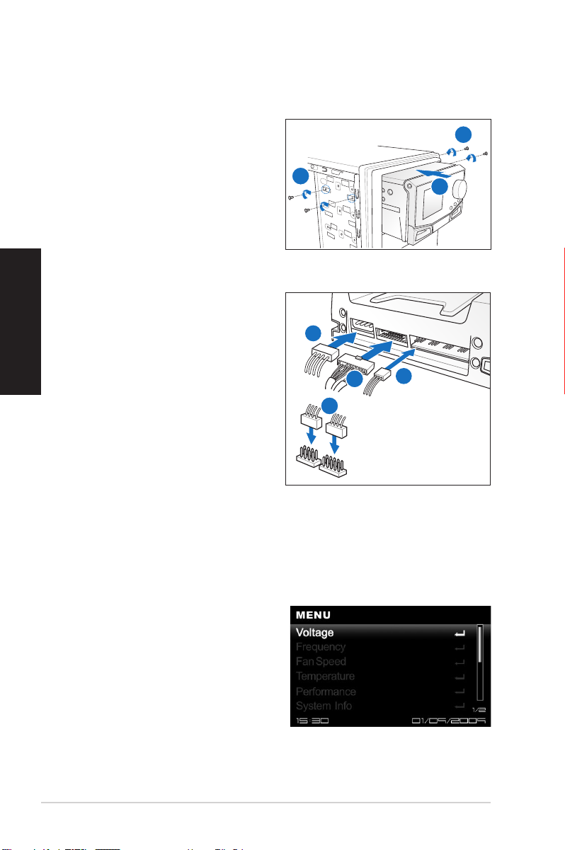
Hardware installation
OC Station installation
1. Insert the OC Station to the empty
5.25” drive bays.
2. Secure the OC Station with four
screws.
Cable connection
1. Connect one end of the supplied
data cable to the GP connector on
the OC Station.
2. Connect the other end of the
supplied data cable to the GP
and USB1112/GP_OC_Station
connectors on the motherboard.
3. Connect an ATX 4-pin power plug
from the system power supply to
the POWER connector.
4. You may connect the extra fans
to the fan connectors on the OC
Station.
Using the OC Station
1. After connecting the OC Station to the motherboard, press the Power buttonAfter connecting the OC Station to the motherboard, press the Power button
to turn on the OC Station display.
2. Rotate the Control knob to go to theRotate the Control knob to go to the
desired item, and then press OK to
enter its submenu.
3. After selecting an item, rotateAfter selecting an item, rotate
clockwise or counter-clockwise to
increase of decrease the value.
4. Press OK to apply settings or
BACK to return to the previous
page and discard the changes.
4
3
1
2
2
21

Français
OC Station
Contrôleur d’overclocking ROG
Guide d’installation rapide

2 ASUS OC Station
Franàais
Résumé des spécications
Écran LCD TFT 3”
Caractéristiques
principales
- Pur support d’overclocking matériel
- Ajustement dynamique des Voltages, fréquences et
vitesses de ventilation
- Afchagedesinformationssystèmeentempsréel
- Diaporama photo
- Design attrayant avec une façade détachable
- IntégrationuideavecROG“CPULevelUp”et“ASUS
EPU”
* Pour travailler dans des conditions optimales avec CPU
Level Up et ASUS EPU, assurez-vous d’avoir mis à jour
AI Suite sur la version S1.05.27 et EPU sur la version
1.01.11 ou ultérieure, puis lancez l’utilitaire de mise à
jourdurmwarepourtraiterlesdonnées.
Autres fonctionnalités - Code de déboguage au démarrage : Post et String
- Systèmed’alarmepournotierlesexcès
- 8prolsdecongurationdisponibles
Autres fonctionnalités - Codes de déboguage de démarrage : Post et String
- Paliers d’alerte avec alarme audio
- 8prolsdeparamètresdisponibles
Ports E/S Alimentation : 1 x connecteur ATX 4 broches
GP : 1 x port de connexion de données 20 broches
Ventilation : 4 x connecteurs 3 broches pour ventilateurs
additionnels
Alimentation Voltage : +12V, +5V, +5VSB
Consommation électrique : 5A
Pré requis pour
l’installation
2 x baies 5.25” requises pour l’installation
1 câble d’alimentation 4 broches pour le bloc
d’alimentation du PC
Compatibilité CartesmèresRampageIIExtreme,CrosshairIIIFormula,
et ROG GENE
* Visitez le site Web d’ASUS sur www.asus.com pour la
dernièredescartesmèrescompatibles.
**MettezàjourleBIOSdelacartemèredanssaversion
la plus récente pour une meilleure compatibilité.
* Les spécications sont sujettes à modication sans avis préalable.

ASUS OC Station 3
Français
Introduction du matériel
Vue avant
Vue arrière
1. Écran :afchelesoptionsdeconguration.
2. Molette de contrôle : permet de sélectionner un élément ou ajuster une
valeur.
3. Bouton Marche/Arrêt :unefoisconnectéàlacartemère,appuyezsurce
bouton pour allumer ou éteindre l’écran OC Station.
4. Bouton BACK: appuyez pour retourner à la page précédente ou annuler un
réglage.
5. Bouton OK : appuyez pour sélectionner l’élément désiré ou appliquer un
réglage.
6. Bouton de façade : appuyez pour ouvrir la façade dans un angle de 30°.
12
1
65
4
3
1. Connecteur d’alimentation : se connecte à une prise ATX 4 broches.
2. Connecteurs de ventilation : se connecte aux ventilateurs additionnels.
3. Connecteur GP :seconnecteàunecartemèrecompatible.
1
2
3

4 ASUS OC Station
Franàais
Installation du matériel
Installation de OC Station
1. Insérez OC Station sur les baies
5.25” de votre ordinateur.
2. Sécurisez OC Station à l’aide de
quatre vis.
Connexion des câbles
1. Connectez une extrémité du câble
fourni au connecteur GP d’OC
Station.
2. Connectez l’autre extrémité du
câble aux connecteurs GP et
USB1112/GP_OC_Station de la
cartemère.
3. Connectez l’une des prises ATX 4
broches du bloc d’alimentation au
connecteur POWER.
4. Vous pouvez connecter des
ventilateurs additionnels via les
connecteurs appropriés d’OC
Station.
Utiliser OC Station
1. AprèsavoirconnectéOCStationàlacartemère,appuyezsurleboutonde
mise en route d’OC Station pour allumer l’écran.
2. Tournez la molette de contrôle pour
sélectionner un élément et appuyez
sur OK pour accéder à son sous-
menu.
3. Aprèsavoirsélectionnéunélément,
tournez la molette vers la droite
ou la gauche pour augmenter ou
baisser la valeur sélectionnée.
4. Appuyez sur OKpourappliquerlesmodicationsousurBACK pour
retourneràlapageprécédenteetannulerlesmodications.
4
3
1
2
2
21

Deutsch
OC-Station
ROG OC Controller
Schnellinstallationsanleitung

2 ASUS OC-Station
Deutsch
Technische Spezikationen
Anzeige 3” TFT LCD
Schlüsselfunktionen - Komplett Hardware-basierende Übertaktungsunterstützung
- Regelbare Systemspannungen, Frequenzen und
Lüftergeschwindigkeiten im laufenden Betrieb
- Anzeige der Systeminformationen in Echtzeit
- Diashow
- Modisches Design mit bis zu 30º kippbarer Frontblende
- Nahtlose Unterstützung von ROG exklusives CPU-Level-
Up und ASUS EPU
* Um ordnungsgemäß mit CPU-Level-Up und ASUS EPU
zu arbeiten, vergewissern Sie sich, dass Sie AI Suite
auf Version S1.05.27 und EPU auf Version 1.01.11
oder eine neuere Version aktualisiert haben und starten
Sie das Firmware-Aktualisierungsprogramm, um die
Datenverarbeitung durchzuführen.
Sonstige Funktionen - Boot-Debug-Code: Post und String
- Alarm für Grenzwerte durch Audio-Alarm
- Prolenstellungenin8Gruppenverfügbar
E/A-Anschlüsse POWER: 1 x ATX 4-pol. Stromanschluss
GP: 1 x 20-pol. Datenverbindung
FAN: 4 x 3-pol. Anschlüsse für zusätzliche Lüfter
Stromversorgung Spannung: +12V, +5V, +5VSB
Stromaufnahme: 5A
Systemanforderungen 2 x 5.25” Laufwerksschächte für Einbau erforderlich
1x 4-pol. Stromversorgungskabel vom Systemnetzteil
Kompatibilität Rampage II Extreme-, Crosshair III Formula- und ROG
GENE-Serie-Motherboards
* Besuchen Sie die ASUS-Webseite unter www.asus.
com für die neuste Liste der unterstützten/kompatiblen
Motherboards.
** Für eine bessere Kompatibilität aktualisieren Sie bitte das
Motherboard-BIOS auf die neuste Version.
* Die Spezikationen können ohne vorherige Ankündigung geändert werden.

ASUS OC-Station 3
Deutsch
Hardware-Einführung
Frontansicht
Rückseite
1. Anzeige:ZeigtdieKongurationsoptionenan.
2. Steuerknopf: Drehen, um das gewünschte Element auszuwählen oder die
Werte einzustellen.
3. Einschalter: Wenn mit dem Motherboard verbunden, drücken Sie diese
Taste, um die OC-Station-Anzeige ein- oder auszuschalten.
4. Zurück-Taste: Drücken, um zur vorherigen Seie zurückzukehren oder die
Einstellung abzubrechen.
5. OK-Taste: Drücken, um das gewünschte Element auszuwählen oder die
Einstellungen zu übernehmen.
6. Frontblendentaste: Drücken, um, die OC-Station-Frontblende um 30°
anzukippen.
12
1
65
4
3
1. Stromanschluss: Anschluss für einen 4-pol. ATX-Stecker.
2. Lüfteranschlüsse: Anschlüsse für zusätzliche Lüfter.
3. GP-Anschluss: Verbindung zu einen kompatiblen Motherboard.
1
2
3

4 ASUS OC-Station
Deutsch
Hardware-Installation
OC-Station-Installation
1. Schieben Sie die OC-
Station in zwei leere 5.25”
Laqufwerksschächte.
2. Sichern Sie die OC-Station mit vier
Schrauben.
Kabelverbindung
1. Verbinden Sie ein Ende des
mitgelieferten Datenkabels mit dem
GP-Anschluss an der OC-Station.
2. Verbinden Sie das andere
Ende des Datenkabels mit den
Anschlüssen GP und USB1112/
GP_OC_Station Auf dem
Motherboard.
3. Verbinden Sie einen 4-pol. ATX-
Stromversorgungstecker vom
Systemnetzteil mit den POWER-
Anschluss.
4. Sie können über die zusätzlichen
Lüfteranschlüsse der OC-Station noch mehrere Lüfter anschließen.
Benutzen der OC-Station
1. Nachdem Sie die OC-Station mit dem Motherboard verbunden haben,Nachdem Sie die OC-Station mit dem Motherboard verbunden haben,
drücken Sie auf den Einschalter, um die Anzeige der OC-Station
einzuschalten.
2. Drehen Sie den Steuerknopf zumDrehen Sie den Steuerknopf zum
gewünschten Element und drücken
Sie dann auf OK, um dieses
Untermenü aufzurufen.
3. Nachdem Sie ein ElementNachdem Sie ein Element
ausgewählt haben, drehen Sie
den Knopf in oder entgegen der
Uhrzeigerrichtung, um die Werte zu
erhöhen oder zu verringern.
4. Drücken Sie auf OK, um die einstellungen zu übernehmen oder auf Zurück,
um zur vorherigen Seite zurückzukehren und die Einstellungen zu verwerfen.
4
3
1
2
2
21

Italiano
OC Station
ROG OC Controller
Guida Rapida

2 ASUS OC Station
Italiano
Speciche Tecniche
Display LCD TFT da 3”
Caratteristiche
Principali
- Supporto overclock solo su base hardware
- Regolazione tensioni,frequenze e velocità ventola del
sistemaon-the-y.
- Visualizzazione info sul sistema in tempo reale
- Presentazionefotograca
- Design di stile con protezione frontale mobile reclinabile
a 30 gradi.
- Perfetta integrazione con esclusiva funzionalità ASUS
EPU e CPU Level Up per ROG.
* Per un comodo funzionamento di CPU Level Up e ASUS
EPU, assicurarsi di aver aggiornato AI Suite a S1.05.27 e
EPU a 1.01.11 o versioni successive, ed avviare l’utilità di
aggiornamentodelrmwareperl’elaborazionedati.
Altre caratteristiche - Codice debug avvio: Post and String
- Soglie di allarme con avvertimenti audio.
- 8setdiimpostazioniprolodisponibili
Porte I/O POWER: 1 x connettore alimentazione a 4-pin ATX
GP: 1 x Porta connessione dati a 20-pin
FAN: 4 x connettori ventola extra a 3-pin
Alimentazione Voltaggio: +12V, +5V, +5VSB
Consumo: 5A
Requisiti di installazione 2 x alloggi da 5.25” necessari per l’installazione
1 x cavo di alimentazione 4-pin dall’ unità di
alimentazione del PC.
Compatibilità Schede madri serie: Rampage II Extreme, Crosshair III
Formula e ROG GENE
* Visitare il sito web ASUS www.asus.com per gli elenchi
aggiornati supporto/compatibilità schede madri.
** Aggiornare il BIOS della scheda madre all’ultima
versione, per una migliore compatibilità.
* Le speciche sono soggette a modiche senza obbligo di preavviso.

ASUS OC Station 3
Italiano
Descrizione Hardware
Lato Frontale
Lato Posteriore
1. Display:mostraleopzionidicongurazione.
2. Manopola di Controllo: da ruotare per selezionare le voci prescelte o per
regolare i valori.
3. Pulsante di Accensione: non appena collegati alla scheda madre, premere
questo pulsante per attivare/disattivare il display di OC Station.
4. Pulsante BACK: da premere per ritornare alla pagina precedente o per
annullare le impostazioni.
5. Pulsante OK: da premere per selezionare le voci prescelte o per applicare le
impostazioni.
6. Pulsante del PannelloPannello: da premere per aprire il pannello di OC Station ad
un angolo di 30°.
12
1
65
4
3
1. Connettore POWER: collega ad una spina per l’alimentazione a 4-pin ATX.
2. Connettori FAN: collegano a ventole aggiuntive.
3. Connettore GP: collega alla scheda madre compatibile.
12
3

4 ASUS OC Station
Italiano
Installazione Hardware
Installazione di OC Station
1. Inserire OC Station negli alloggi
drive vuoti da 5.25”.
2. Fissare OC Station con quattro viti.
Connessione dei Cavi
1. Collegare un’estremità del cavo in
dotazione al connettore GP su OC
Station.
2. Collegare l’estremità del cavo
in dotazione ai connettori GP e
USB1112/GP_OC_Station sulla
scheda madre.
3. Collegare una spina per
l’alimentazione ATX a 4-pin
dall’alimentazione del sistema al
connettore POWER.
4. Si possono collegare ventole
aggiuntive ai connettori per le
ventole su OC Station.
Utilizzo di OC Station
1. Dopo aver collegato OC Station alla scheda madre, premere il pulsante diDopo aver collegato OC Station alla scheda madre, premere il pulsante di
accensione per accendere il display di OC Station.
2. Ruotare la manopola di controlloRuotare la manopola di controllo
per selezionare la voce desiderata
e premere OK per accedere al
relativo sottomenu.
3. Dopo aver selezionato una voce,Dopo aver selezionato una voce,
ruotare la manopola in senso
orario o antiorario per aumentare o
diminuire il valore .
4. Premere OK per applicare le impostazioni o BACK per tornare alla pagina
precedenteeignorarelemodiche.
4
3
1
2
2
21

Español
OC Station
Controlador ROG OC
Guía de instalación rápida

2 ASUS OC Station
Español
Resumen de especicaciones
Pantalla LCD TFT de 3”
Características
principales
- Compatibilidad con aumento de la velocidad de reloj
basado puramente en hardware
- Ajuste del voltaje del sistema, frecuencias y velocidad de
ventilador sobre la marcha.
- Visualización de temperaturas en tiempo real
- Presentación de diapositivas de las fotografías
- Diseño elegante. La placa frontal se puede mover e
inclinar hasta 30 grados
- Integración transparente con tecnología CPU Level Up
(Actualización de CPU) de ROG y ASUS EPU (Unidad
de Procesamiento de Energía)
* *Para obtener un óptimo rendimiento con CPU Level Up
y ASUS EPU, asegúrese de que ha actualizado AI Suite
con la versión S1.05.27 y EPU con la versión 1.01.11
ó posterior, e inicie la utilidad de actualización del
rmwareparaprocederalprocesamientodedatos.
Otras características - Código de depuración de arranque: Post y String
- Umbrales de alarma con alerta acústica
- 8conjuntosdeconguracionesdeperldisponibles
Puertos de E/S ALIMENTACIÓN: 1 conector de alimentación de 4
contactos ATX
GP: 1 puerto de conexión de datos de 20 contactos
VENTILADOR: 4 conectores de 3 contactos para
ventiladores adicionales
Alimentación Voltaje: +12 V, +5 V, +5 VSB
Consumo de energía: 5 A
Requisitos de
instalación
Se requieren 2 bahías de disco de 5,25” para la
instalación
1 Cable de alimentación de 4 pines para alimentación del
sistema
Compatibilidad Placas base de la serie Rampage II Extreme, Crosshair III
Formula y ROG GENE
* Visite el sitio Web de ASUS en www.asus.com paraVisite el sitio Web de ASUS en www.asus.com paraVisite el sitio Web de ASUS en www.asus.com para
obtener la listas de placas base compatibles más
recientes.
** Actualice el BIOS de la placa base a la última versiónActualice el BIOS de la placa base a la última versiónActualice el BIOS de la placa base a la última versión
para mejorar la compatibilidad.
*Las especicaciones están sujetas a cambio sin previo aviso.
Table of contents
Other Asus Controllers manuals
Popular Controllers manuals by other brands

Calpeda
Calpeda IDROMAT Series Original operating instructions

Sonos
Sonos Controller CR100 Quick setup instructions

Siemens
Siemens SIPART DR19 quick reference

Madas
Madas RG/2MBLZ DN 80 Technical manual

Dungs
Dungs hiltbrand DGAI. 69F Customer's operating and assembly instructions

COMECO
COMECO PSF210 Series Operation manual