Manual Contents
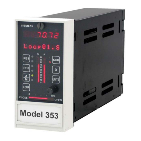
SIPART DR22 6DR2210
C79000-G7476-C154-03 5
Conents
Page
1 Technical Description 7...................................................
1.1 Safety notes and scope of delivery 7..................................................
1.2 Range of Application 8..............................................................
1.3 Design (Hardware) 9...............................................................
1.4 Function principle 12................................................................
1.4.1 Standard controller 12.................................................................
1.4.2 Description of the option modules 13....................................................
1.4.3 CPU self-diagnostics 20...............................................................
1.4.4 Data storage, User program memory 21.................................................
1.5 Functional description of the structure switches 22.......................................
1.5.1 Analog input signal processing permanently connected 22..................................
1.5.2 Analog input signal processing freely connected (S4 = 1) 25.................................
1.5.2.1 Arithmetic Ar1 to Ar6 27...............................................................
1.5.2.2 Function transmitter Fu1 and Fu2 27....................................................
1.5.2.3 Maximum value selection MA1 to MA3 27................................................
1.5.2.4 Minimum value selection Mi1 to Mi3 28...................................................
1.5.2.5 Correction computer for ideal gases rE1 28...............................................
1.5.2.6 Switch for analog variables AS1 to AS5 33...............................................
1.5.2.7 Comparator with adjustable hysteresis Co1, Co2 33........................................
1.5.2.8 AND NOT function (NAND) nA1, nA2 33.................................................
1.5.2.9 OR NOT function (NOR) no1, no2 33....................................................
1.5.3 Digital input signal processing 34.......................................................
1.5.3.1 Digital inputs BE1 to BE14 34..........................................................
1.5.3.2 Assignment and direction of effect of the digital inputs 35....................................
1.5.3.3 Linking the digital inputs BE1 bis BE14 to the control signals via the SES 35...................
1.5.3.4 Functional explanation of the digital control signals 39......................................
1.5.4 Controller types (S1, S49 to S53) 40.....................................................
1.5.4.1 General, recurrent functions 40.........................................................
1.5.4.2 S1 = 0: Fixed setpoint controller with 2 independent setpoints 48...........................
1.5.4.3 S1= 1: Fixed setpoint controller with 2 dependent setpoints 51.............................
1.5.4.4 S1 = 2: DDC fixed setpoint controller 52................................................
1.5.4.5 S1 = 3: Follow-up controller, synchronized controller, SPC-controller 58.....................
1.5.4.6 S1 = 4: commanded ratio controller 64.................................................
1.5.4.7 S1 = 5: Cascade control 69..........................................................
1.5.4.8 S1 = 6: Ratio-cascade control 74......................................................
1.5.4.9 S1 = 7/8: Override control 77...........................................................
1.5.4.10 S1 = 9: Process display 83...........................................................
1.5.4.11 S1 = 10: Fixed setpoint controller with 1 setpoint (control system coupling) 84.................
1.5.4.12 S1 = 11: Follow-up controller without Int/Ext switching (control system coupling) 85.............
1.5.4.13 S1=12: Double fixed setpoint/follow-up controller 86......................................
1.5.5 Control algorithm, parameter control, adaptation 89........................................
1.5.5.1 Control algorithm 89..................................................................
1.5.6 Controller output structures (S2, S61 to S68) 99...........................................
1.5.6.1 S2 = 0: Continuous (K) controller 99...................................................
1.5.6.2 S2 = 1: Three-position step (S) -controller with internal feedback 104.........................
1.5.6.3 S2 = 2: Three-position step (S) -- controller with external feedback 107.......................
1.5.7 Analog output signal processing (S69 to S75, S247 to S257) 120..............................
1.5.8 Digital output signal processing (S76 to S93 and S258 to S266) 121...........................
1.5.9 Limit value alarms (S94 to S100, S267 to S268) 124........................................
1.5.10 Restart conditions (S99, S100) 126.......................................................
1.5.11 Serial interface and PROFIBUS-DP (S101 to S107) 126.....................................
1.6 Technical Data 127...................................................................
1.6.1 General data 127......................................................................
1.6.2 Standard Controller 129................................................................
1.6.3 Technical data of the options modules 133.................................................
