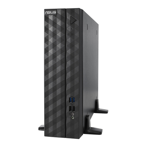
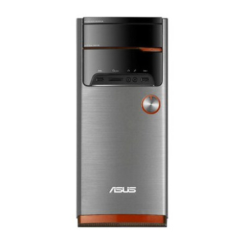
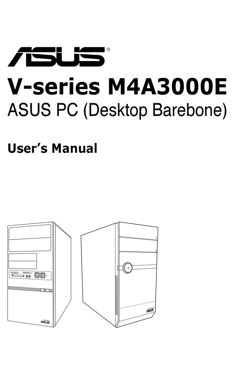
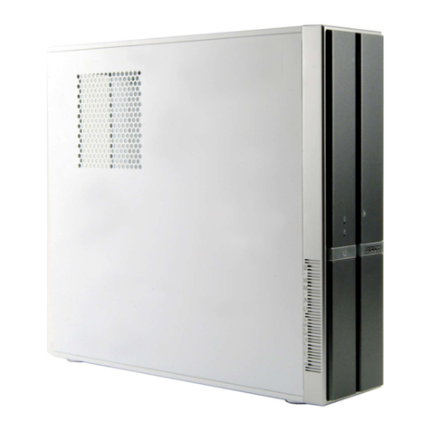
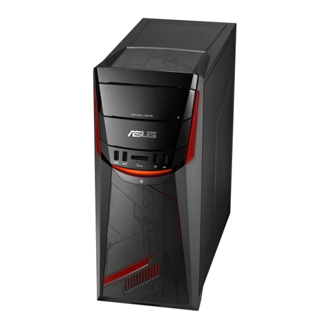
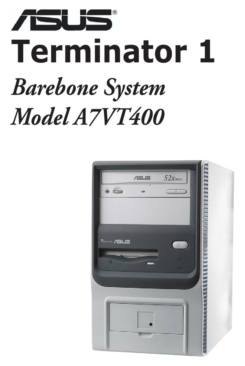
Asus T2-AE1 User manual

English
®
T2-AE1
Barebone System
Quick Installation Guide
Copyright © 2005 ASUSTeK COMPUTER INC. All Rights Reserved.Copyright © 2005 ASUSTeK COMPUTER INC. All Rights Reserved.
Copyright © 2005 ASUSTeK COMPUTER INC. All Rights Reserved.

iiii
iiii
ii
English
System package contents
Check your T2-AE1 system package for the following items. Contact your
retailer immediately if any of the items is damaged or missing.
Item descItem desc
Item descItem desc
Item desc
riptionription
riptionription
ription
1.1.
1.1.
1. ASUS Terminator 2 barebone systemASUS Terminator 2 barebone system
ASUS Terminator 2 barebone systemASUS Terminator 2 barebone system
ASUS Terminator 2 barebone system with
• ASUS motherboard
• 200 W PFC power supply unit
• 10/100 Mbps Ethernet LAN port
• CPU fan and heatsink assembly
• 2 x 5.25” drive bays
• 1 x 3.5” floppy disk drive bay
• 1 x 3.5” hard disk drive bay
• 6 x USB 2.0 ports
• 2 x IEEE 1394a ports
• S/PDIF out port
2.2.
2.2.
2. CablesCables
CablesCables
Cables
• AC power cable
• Serial ATA cable
• Serial ATA power cable
• 2-in-1 disk drive cable
• Floppy disk drive cable
3.3.
3.3.
3. Support CDSupport CD
Support CDSupport CD
Support CD
4.4.
4.4.
4. User guideUser guide
User guideUser guide
User guide
5.5.
5.5.
5. Optional itemsOptional items
Optional itemsOptional items
Optional items
• Optical drive
(CD-ROM/CD-RW/DVD-ROM/DVD-RW)
• Floppy disk drive
Features
Front panel (external)Front panel (external)
Front panel (external)
33
33
3
Optical drive doorOptical drive door
Optical drive door
Floppy drive doorFloppy drive door
Floppy drive door
Second optical driveSecond optical drive
Second optical drive
doordoor
doordoor
door
Eject buttonEject button
Eject button
Power buttonPower button
Power button
Power LEDPower LED
Power LEDPower LED
Power LED
HDD LEDHDD LED
HDD LEDHDD LED
HDD LED
Front panel I/O doorFront panel I/O door
Front panel I/O door

iiiiii
iiiiii
iii
English
Front panel (internal)Front panel (internal)
Front panel (internal)
Floppy disk driveFloppy disk drive
Floppy disk drive Optical driveOptical drive
Optical driveOptical drive
Optical drive
(optional)(optional)
(optional)
USB 2.0 portsUSB 2.0 ports
USB 2.0 ports
Headphone portHeadphone port
Headphone port
Microphone portMicrophone port
Microphone port
4-pin IEEE 1394a port4-pin IEEE 1394a port
4-pin IEEE 1394a port
6-pin IEEE 1394a port6-pin IEEE 1394a port
6-pin IEEE 1394a port
Rear panelRear panel
Rear panel
GAME/MIDI portGAME/MIDI port
GAME/MIDI port
Optical S/PDIF portOptical S/PDIF port
Optical S/PDIF port
Serial portSerial port
Serial port
PS/2 mouse portPS/2 mouse port
PS/2 mouse port
PS/2 keyboard portPS/2 keyboard port
PS/2 keyboard port
VGA portVGA port
VGA portVGA port
VGA port
Parallel portParallel port
Parallel port
Line Out portLine Out port
Line Out port
Line In portLine In port
Line In port
Microphone portMicrophone port
Microphone port
USB 2.0 portsUSB 2.0 ports
USB 2.0 ports
LAN (RJ-45) portLAN (RJ-45) port
LAN (RJ-45) port
Expansion slotExpansion slot
Expansion slot
coverscovers
coverscovers
covers
Chassis fan ventChassis fan vent
Chassis fan vent
Power supply unitPower supply unit
Power supply unit
fan ventfan vent
fan ventfan vent
fan vent
Voltage selectorVoltage selector
Voltage selector
Power connectorPower connector
Power connector
Expansion card lockExpansion card lock
Expansion card lock

iviv
iviv
iv
English
Installation
IMPORTANT!IMPORTANT!
IMPORTANT! Refer to the system user guide for installation details
and other system information.
Removing the coverRemoving the cover
Removing the cover
1. Locate and remove three
cover screws.
AA
AA
A
AA
AA
A
BB
BB
B
2. Pull the cover toward the rear
panel (A), then lift (B).
Removing the power supply unitRemoving the power supply unit
Removing the power supply unit
1. Disconnect all power plugs
from the system components
and the motherboard, then
remove the PSU screw.
2. Slide the PSU to the left (A)
until the side hook is
disengaged. Push the PSU
toward the front panel (B),
then lift (C).
AA
AA
A
BB
BB
B
CC
CC
C
IMPORTANT!IMPORTANT!
IMPORTANT! When removing the PSU, make sure to hold or support it
firmly. The unit might accidentally drop and damage the other system
components.

vv
vv
v
English
Installing the CPUInstalling the CPU
Installing the CPU
1. Press the CPU
socket lever
sideways, then lift.
2. Insert the CPU into
the socket until it
fits in place.
3. Push down the
socket lever to
secure the CPU.
IMPORTANT!IMPORTANT!
IMPORTANT! Make sure to install the CPU fan and heatsink assembly
on top of the installed CPU.
Installing the CPU fan and heatsink assemblyInstalling the CPU fan and heatsink assembly
Installing the CPU fan and heatsink assembly
11
11
1
22
22
2
1. Place the CPU fan
and heatsink
assembly on top
of the installed
CPU, making sure
it fits the
retention module.
2. Connect the CPU
fan cable to the
CPU fan
connector on the
motherboard.
3. Align the metal
clips to the side
rail of the CPU fan
and heatsink
assembly, with
the locking levers
in the reverse
orientation.
4. Snap the hook of
each metal clip
into the hole of
the retention
module.
33
33
333
33
3
44
44
444
44
4
5. Carefully press
down each locking
lever and hook its
end into the hole
of the retention
module.
55
55
5
55
55
5
IMPORTANT!IMPORTANT!
IMPORTANT! Make sure to turn off your computer and unplug the
cable from the power source before installing the CPU fan and heatsink
assembly.

vivi
vivi
vi
English
Installing memory module(s)Installing memory module(s)
Installing memory module(s)
1. Press the
retaining clips of
the DIMM socket
outward.
2. Align a DIMM on
the socket.
3. Insert the DIMM
firmly to the
socket until the
retaining clips snap
back in place.
CAUTION!CAUTION!
CAUTION!CAUTION!
CAUTION! A DDR DIMM is keyed with a notch so that it fits in only one
direction. Do not force a DIMM into a socket to avoid damaging the DIMM!
Installing expansion cardsInstalling expansion cards
Installing expansion cards
1. Pull the expansion card lock to
the direction of the arrow.
2. Remove the metal bracket
opposite the slot you intend to
use.
3. Align the card connector
with the slot, then press
firmly.

viivii
viivii
vii
English
Installing a hard disk driveInstalling a hard disk drive
Installing a hard disk drive
1. Remove the HDD tray lock
screw.
2. Slide the HDD tray outward.
3. Place a hard disk drive on the
tray, then secure it with four
screws.
4. Reinstall the HDD tray inside
the chassis, then secure the
HDD tray with the lock screw.
5. Connect the power and signal
cables to the connectors at
the back of the drive.
NOTE.NOTE.
NOTE.NOTE.
NOTE. Refer to the User
Guide for details on installing a
Serial ATA HDD.

viiiviii
viiiviii
viii
English
Selecting the voltage
The PSU has a 115 V/230 V voltage selector
switch located beside the power connector. Use
this switch to select the appropriate system
input voltage according to the voltage supply in
your area.
NOTE.NOTE.
NOTE.NOTE.
NOTE. The voltage selector is set to
230 V by default.
If the voltage supply in your area is 100-127 V,
set the switch to 115 V. If the voltage supply in
your area is 200-240 V, set the switch to 230 V.
WARNING!WARNING!
WARNING!WARNING!
WARNING! Setting the switch to 115 V in a 230 V environment will
seriously damage the system!
Replacing the coverReplacing the cover
Replacing the cover
1. Fit the cover tabs with the
chassis rail and the front panel
tabs (A), then lower the rear
edge of the cover as shown
(B).
2. Secure the cover with three
screws.
AA
AA
AAA
AA
A
BB
BB
BBB
BB
B

Français
®
T2-AE1
Système barebone
Guide d’installation rapide
Copyright © 2005 ASUSTeK COMPUTER INC. Tous droits réservés.Copyright © 2005 ASUSTeK COMPUTER INC. Tous droits réservés.
Copyright © 2005 ASUSTeK COMPUTER INC. Tous droits réservés.

iiii
iiii
ii
Français
Contenu du carton
Vérifiez que les éléments suivants accompagnent bien votre T2-AE1.
Contactez votre revendeur immédiatement si l’un d’entre eux était
manquant ou endommagé.
Caractéristiques
Façade (externe)
Trappe du lecteur optiqueTrappe du lecteur optique
Trappe du lecteur optique
Trappe du lecteur deTrappe du lecteur de
Trappe du lecteur de
disquettesdisquettes
disquettes
Seconde trappe deSeconde trappe de
Seconde trappe de
lecteur optiquelecteur optique
lecteur optique
Bouton d’éjectionBouton d’éjection
Bouton d’éjection
Bouton d’alimentationBouton d’alimentation
Bouton d’alimentation
LED d’alimentationLED d’alimentation
LED d’alimentation
LED du disque durLED du disque dur
LED du disque dur
Trappe d’E/S en façadeTrappe d’E/S en façade
Trappe d’E/S en façade
LEDsLEDs
LEDsLEDs
LEDs
Description des élémentsDescription des éléments
Description des éléments
1.1.
1.1.
1. Système barebone ASUS Terminator 2Système barebone ASUS Terminator 2
Système barebone ASUS Terminator 2Système barebone ASUS Terminator 2
Système barebone ASUS Terminator 2 avec
•Carte mère ASUS
•Alimentation 200 W PFC
•Port Ethernet LAN 10/100 Mbps
•Assemblage dissipateur/ventilateur pour CPU
•2 x baies 5.25”
•1 x baie pour lecteur de disquettes 3.5”
•1 x baie pour disque dur 3.5”
•6 x ports USB 2.0
•2 x ports IEEE 1394a
•Port de sortie S/PDIF
2.2.
2.2.
2. CâblesCâbles
CâblesCâbles
Câbles
•Câble d’alimentation
•Câble Serial ATA
•Câble d’alimentation Serial ATA
•Câble 2-en-1 pour lecteur
•Câble pour lecteur de disquettes
3.3.
3.3.
3. CD de supportCD de support
CD de supportCD de support
CD de support
4.4.
4.4.
4. ManuelManuel
ManuelManuel
Manuel
5.5.
5.5.
5. Eléments optionnelsEléments optionnels
Eléments optionnelsEléments optionnels
Eléments optionnels
•Lecteur optique
(CD-ROM/CD-RW/DVD-ROM/DVD-RW)
•Lecteur de disquettes

iiiiii
iiiiii
iii
Français
Façade (interne)Façade (interne)
Façade (interne)
Lecteur de disquettesLecteur de disquettes
Lecteur de disquettes Lecteur optiqueLecteur optique
Lecteur optiqueLecteur optique
Lecteur optique
(optionnel)(optionnel)
(optionnel)
Ports USB 2.0Ports USB 2.0
Ports USB 2.0
Port CasquePort Casque
Port Casque
Port MicrophonePort Microphone
Port Microphone
Port IEEE 1394a 4 brochesPort IEEE 1394a 4 broches
Port IEEE 1394a 4 broches
Port IEEE 1394a 6 brochesPort IEEE 1394a 6 broches
Port IEEE 1394a 6 broches
ArrièreArrière
ArrièreArrière
Arrière
Port GAME/MIDIPort GAME/MIDI
Port GAME/MIDI
Port S/PDIF optiquePort S/PDIF optique
Port S/PDIF optique
Port SériePort Série
Port Série
Port souris PS/2Port souris PS/2
Port souris PS/2
Port clavier PS/2Port clavier PS/2
Port clavier PS/2
Port VGAPort VGA
Port VGAPort VGA
Port VGA
Port ParallèlePort Parallèle
Port Parallèle
Port Line OutPort Line Out
Port Line Out
Port Line InPort Line In
Port Line In
Port MicrophonePort Microphone
Port Microphone
Ports USB 2.0Ports USB 2.0
Ports USB 2.0
Port LAN (RJ-45)Port LAN (RJ-45)
Port LAN (RJ-45)
Couverture desCouverture des
Couverture des
slots d’extensionslots d’extension
slots d’extension
Ventilation châssisVentilation châssis
Ventilation châssis
VentilationVentilation
Ventilation
alimentationalimentation
alimentation
Sélecteur de tensionsSélecteur de tensions
Sélecteur de tensions
Connecteur d’alimentaitonConnecteur d’alimentaiton
Connecteur d’alimentaiton
Verrou des cartesVerrou des cartes
Verrou des cartes
d’extensiond’extension
d’extension

iviv
iviv
iv
Français
Installation
IMPORTANT !IMPORTANT !
IMPORTANT ! reportez-vous au manuel pour plus de détails
d’installation et autres informations système.
Ouvrir le châssisOuvrir le châssis
Ouvrir le châssis
1. Localisez et dévissez les trois
vis de châssis.
AA
AA
A
AA
AA
A
BB
BB
B
2. Tirez vers l’arrière (A), puis
levez (B).
Enlever l’alimentationEnlever l’alimentation
Enlever l’alimentation
1. Déconnectez toutes les prises
d’alimentaiton du système et
des composants puis enlevez
la vis de l’alimentation.
2. Glissez l’alimentation vers la
gauche (A) jusqu’à ce que les
crochets soient désengagés.
Poussez l’alimentation vers la
façade (B), puis soulevez (C).
AA
AA
A
BB
BB
B
CC
CC
C
IMPORTANT !IMPORTANT !
IMPORTANT ! lorsque vous enlevez l’alimentation assurez-vous de
bien la tenir car elle pourrait tomber et endommager les autres
composants du système.

vv
vv
v
Français
Installer le CPUInstaller le CPU
Installer le CPU
1. Pressez le levier
du socket du CPU
latéralement, puis
souvevez.
2. Insérez le CPU
dans le socket
jusqu’à ce qu’il
soit bien en place.
3. Rabaissez le levier
du CPU pour le
verrouiller.
IMPORTANT !IMPORTANT !
IMPORTANT ! Assurez-vous de bien installer le système de ventilation
sur le CPU installé.
Installer le système de refroidissement du CPUInstaller le système de refroidissement du CPU
Installer le système de refroidissement du CPU
11
11
1
22
22
2
1. Placez le système
de refroidissement
du CPU sur le CPU
installéen vous
assurant qu’il entre
dans le module de
rétention.
2. Connectez le câble
du ventilateur du
CPU au connecteur
de la carte mère.
3. Alignez les clips
métalliques sur
les rails latéraux
de l’ensemble
dissipateur-
ventilateur, avec
les leviers de
verrouillage
ouverts.
4. Accrochez le
crochet de
chaque clip
métallique dans le
trou du module de
rétention.
33
33
333
33
3
44
44
444
44
4
5. Rabaissez avec
soin chaque levier
de verrouillage et
accrochez-en
l’extrémitéau trou
du module de
rétention.
55
55
5
55
55
5
IMPORTANT!IMPORTANT!
IMPORTANT! Assurez-vous d’éteindre l’ordinateur et de débrancher le
câble d’alimentation avant d’installer l’ensemble dissipateur/ventilateur.

vivi
vivi
vi
Français
Installer des modules de mémoireInstaller des modules de mémoire
Installer des modules de mémoire
1. Pressez les clips
de rétention des
sockets DIMM
vers l’extérieur.
2. Alignez un module
sur le socket.
3. Insérez le module
DIMM dans le
socket jusqu’à ce
que lec clips
reviennent en
place.
ATTENTIONATTENTION
ATTENTIONATTENTION
ATTENTION !!
!!
! Un module DIMM DDR est verrouillépar une encoche de
sorte qu’il ne puisse entrer que dans un seul sens. Ne forcez pas
inutilement sur un module pour ne pas l’endommager.
Installer les cartes d’extensionInstaller les cartes d’extension
Installer les cartes d’extension
1. Tirez le verrou de cartes
d’extension dans le sens de la
flèche.
2. Enlevez la protection
métallique du slot que vous
voulez utiliser.
3. Positionnez le connecteur de
la carte sur le slot, puis
pressez fermement.

viivii
viivii
vii
Français
Installer un disque durInstaller un disque dur
Installer un disque dur
1. Dévissez le plateau du disque
dur.
2. Sortez le plateau.
3. Placez le disque dur sur le
plateau puis fixez-le avec
quatre vis.
4. Reinstallez le plateau du
disque dur dans le châssis puis
remettez la vis de fixation.
5. Connectez les câbles de signal
et d’alimentation aux prises à
l’arrière du disque.
NOTE.NOTE.
NOTE.NOTE.
NOTE. reportez-vous au
manuel pour plus de détails sur
l’installation d’un disque dur
Serial ATA.

viiiviii
viiiviii
viii
Français
Refermer le châssisRefermer le châssis
Refermer le châssis
1. Alignez les onglets du capot
avec le rail du châssis et les
onglets de la façade (A), puis
baissez le bord arrière comme
indiqué(B).
2. Fixez le capot avec trois vis.
C oisir le voltage
L’alimentation est équipée d’un sélecteur de
tension 115 V/230 V situéprès du connecteur
d’alimentation. Utilisez cet interrupteur pour
choisir la tension d’entrée appropriée àvotre
région.
NOTE.NOTE.
NOTE.NOTE.
NOTE. le sélecteur de tension est placé
sur 230 V par défaut.
Si la tension dans votre région est de 100-127
V, passez l’interrupteur sur 115 V. Si la tension
dans votre région est de 200-240 V, passez l’interrupteur sur 230 V.
ATTENTION !ATTENTION !
ATTENTION ! Paser l’interrupteur sur 115 V dans une région à230 V
endommagera gravement le système !
AA
AA
AAA
AA
A
BB
BB
BBB
BB
B

Deutsch
®
T2-AE1
Barebone-System
Schnellinstallationsanleitung
Copyright © 2005 ASUSTeK COMPUTER INC. Alle Rechte vorbehalten.Copyright © 2005 ASUSTeK COMPUTER INC. Alle Rechte vorbehalten.
Copyright © 2005 ASUSTeK COMPUTER INC. Alle Rechte vorbehalten.

iiii
iiii
ii
Deutsch
Systempaketinhalt
Die folgenden Artikel gehören zum Lieferumfang des T2-AE1-Systems. Wenden
Sie sich bitte an Ihren Händler, wenn irgendein Artikel beschädigt ist oder fehlt.
Komponenten
Fronttafel (extern)Fronttafel (extern)
Fronttafel (extern)
Tür des optischenTür des optischen
Tür des optischen
LaufwerksLaufwerks
LaufwerksLaufwerks
Laufwerks
Tür desTür des
Tür desTür des
Tür des
DiskettenlaufwerksDiskettenlaufwerks
Diskettenlaufwerks
Tür des zweitenTür des zweiten
Tür des zweiten
optischen Laufwerksoptischen Laufwerks
optischen Laufwerks
AuswurftasteAuswurftaste
Auswurftaste
StromschalterStromschalter
Stromschalter
Betriebs-LEDBetriebs-LED
Betriebs-LED
HDD-LEDHDD-LED
HDD-LEDHDD-LED
HDD-LED
Fronttafel-E/A-TürFronttafel-E/A-Tür
Fronttafel-E/A-Tür
LED-TafelLED-Tafel
LED-TafelLED-Tafel
LED-Tafel
ArtikelbeschreibungArtikelbeschreibung
Artikelbeschreibung
1.1.
1.1.
1. ASUS Terminator 2 Barebone-SystemASUS Terminator 2 Barebone-System
ASUS Terminator 2 Barebone-SystemASUS Terminator 2 Barebone-System
ASUS Terminator 2 Barebone-System mit
•ASUS-Motherboard
•200 W PFC Netzteil
•10/100 Mbps Ethernet LAN-Anschluss
•CPU-Lüfter-Kühlkörper-Einheit
•2 x 5,25" Laufwerkfächer
•1 x 3,5" Diskettenlaufwerkfach
•1 x 3,5" Festplattenfach
•6 x USB 2.0-Anschlüsse
•2 x IEEE 1394a-Anschlüsse
•S/PDIF-Ausgangsanschluss
2.2.
2.2.
2. KabelKabel
KabelKabel
Kabel
•Netzkabel
•Serial ATA-Kabel
•Serial ATA-Stromkabel
•2-in-1 Laufwerkkabel
•Diskettenlaufwerkkabel
3.3.
3.3.
3. Support-CDSupport-CD
Support-CDSupport-CD
Support-CD
4.4.
4.4.
4. BenutzerhandbuchBenutzerhandbuch
BenutzerhandbuchBenutzerhandbuch
Benutzerhandbuch
5.5.
5.5.
5. Optionale ArtikelOptionale Artikel
Optionale ArtikelOptionale Artikel
Optionale Artikel
•Optisches Laufwerk
(CD-ROM/CD-RW/DVD-ROM/DVD-RW)
•Diskettenlaufwerk

iiiiii
iiiiii
iii
Deutsch
Fronttafel (intern)Fronttafel (intern)
Fronttafel (intern)
DiskettenlaufwerkDiskettenlaufwerk
Diskettenlaufwerk OptischesOptisches
OptischesOptisches
Optisches
LaufwerkLaufwerk
LaufwerkLaufwerk
Laufwerk
(optional)(optional)
(optional)
USB 2.0-AnschlüsseUSB 2.0-Anschlüsse
USB 2.0-Anschlüsse
KopfhöreranschlussKopfhöreranschluss
Kopfhöreranschluss
MikrofonanschlussMikrofonanschluss
Mikrofonanschluss
4-pol. IEEE 1394a-4-pol. IEEE 1394a-
4-pol. IEEE 1394a-
AnschlussAnschluss
AnschlussAnschluss
Anschluss
6-pol. IEEE 1394a-6-pol. IEEE 1394a-
6-pol. IEEE 1394a-
AnschlussAnschluss
AnschlussAnschluss
Anschluss
RücktafelRücktafel
RücktafelRücktafel
Rücktafel
GAME/MIDI-AnschlussGAME/MIDI-Anschluss
GAME/MIDI-Anschluss
Optischer S/PDIF-AnschlussOptischer S/PDIF-Anschluss
Optischer S/PDIF-Anschluss
Serieller AnschlussSerieller Anschluss
Serieller Anschluss
PS/2-MausanschlussPS/2-Mausanschluss
PS/2-Mausanschluss
PS/2-TastaturanschlussPS/2-Tastaturanschluss
PS/2-Tastaturanschluss
VGA-AnschlussVGA-Anschluss
VGA-Anschluss
Paralleler AnschlussParalleler Anschluss
Paralleler Anschluss
Line Out-AnschlussLine Out-Anschluss
Line Out-Anschluss
Line In-AnschlussLine In-Anschluss
Line In-Anschluss
MikrofonanschlussMikrofonanschluss
Mikrofonanschluss
USB 2.0-AnschlüsseUSB 2.0-Anschlüsse
USB 2.0-Anschlüsse
LAN (RJ-45)-AnschlussLAN (RJ-45)-Anschluss
LAN (RJ-45)-Anschluss
ErweiterungssteckplatzblendenErweiterungssteckplatzblenden
Erweiterungssteckplatzblenden
Gehäuselüfter-Gehäuselüfter-
Gehäuselüfter-
LüftungsöffnungenLüftungsöffnungen
Lüftungsöffnungen
Netzteilgebläse-Netzteilgebläse-
Netzteilgebläse-
LüftungsöffnungenLüftungsöffnungen
Lüftungsöffnungen
SpannungsschalterSpannungsschalter
Spannungsschalter
StromanschlussStromanschluss
Stromanschluss
ErweiterungssteckplatzriegelErweiterungssteckplatzriegel
Erweiterungssteckplatzriegel

iviv
iviv
iv
Deutsch
Installation
WICHTIG!WICHTIG!
WICHTIG!WICHTIG!
WICHTIG! Sehen Sie bitte im Systembenutzerhandbuch für
Installationsdetails und sonstige Informationen nach.
Entfernen der AbdeckungEntfernen der Abdeckung
Entfernen der Abdeckung
1. Suchen und entfernen Sie die
drei Abdeckungsschrauben.
AA
AA
A
AA
AA
A
BB
BB
B
2. Ziehen Sie die Abdeckung in
Richtung der Rücktafel (A) und
heben sie dann hoch (B).
Entfernen des NetzteilsEntfernen des Netzteils
Entfernen des Netzteils
1. Trennen Sie alle Stromstecker
von den Systemkomponenten
und dem Motherboard und
entfernen dann die
Netzteilschraube.
2. Schieben Sie das Netzteil nach
links (A), bis der seitliche Hake
ausrastet. Drücken Sie das
Netzteil in Richtung der
Fronttafel (B) und heben es
dann hoch (C).
AA
AA
A
BB
BB
B
CC
CC
C
WICHTIG!WICHTIG!
WICHTIG!WICHTIG!
WICHTIG! Achten Sie beim Entfernen des Netzteils darauf, dass Sie das
Netzteil gut festhalten. Das Netzteil kann aus Versehen herunterfallen
und die anderen Systemkomponenten beschädigen.
Table of contents
Languages:
Other Asus Desktop manuals

Asus
Asus T5 Series User manual

Asus
Asus Essentio CG8270 User manual

Asus
Asus P6-M4A3000E User manual

Asus
Asus Pundit P3-PE5 User manual

Asus
Asus Essentio CM1745 User manual

Asus
Asus CM1831-US-3AB User manual

Asus
Asus Essentio CM6730 User manual

Asus
Asus ET2221I/A6410 Series User manual

Asus
Asus AS-D765 User manual

Asus
Asus G22CH User manual

Asus
Asus PUNDIT P2-AE2 User manual

Asus
Asus Essentio ES5100 User manual

Asus
Asus Essentio CG8580 User manual

Asus
Asus P3-PH5 User manual

Asus
Asus ET1602C User manual

Asus
Asus BT1AG User manual

Asus
Asus Vintage-PE2 User manual

Asus
Asus Vintage V2-AH2 User manual

Asus
Asus ET2410IUTS User manual

Asus
Asus BS5000 User manual