Asus VX2Se User manual

Notebook PC
Hardware User’s Manual
E3096 / Jun 2007

2
Contents
Tableof Contents
1. Introducing the Notebook PC
About This User’s Manual ������������������������������������������������������������������������������������������ 6
Notes For This Manual�������������������������������������������������������������������������������������������6
Preparing your Notebook PC�������������������������������������������������������������������������������������� 9
2. Knowing the Parts
Top Side��������������������������������������������������������������������������������������������������������������������12
Bottom Side��������������������������������������������������������������������������������������������������������������14
Right Side�����������������������������������������������������������������������������������������������������������������16
Left Side �������������������������������������������������������������������������������������������������������������������18
Front Side�����������������������������������������������������������������������������������������������������������������20
Rear Side������������������������������������������������������������������������������������������������������������������21
Power Station (optional) ������������������������������������������������������������������������������������������� 22
3. Getting Started
Power System ����������������������������������������������������������������������������������������������������������30
Using AC Power��������������������������������������������������������������������������������������������������� 30
Using Battery Power ��������������������������������������������������������������������������������������������31
Battery Care��������������������������������������������������������������������������������������������������������� 31
Powering ON the Notebook PC ���������������������������������������������������������������������������32
The Power-On Self Test (POST)��������������������������������������������������������������������������32
Checking Battery Power ��������������������������������������������������������������������������������������33
Charging the Battery Pack����������������������������������������������������������������������������������� 33
Power Options ����������������������������������������������������������������������������������������������������� 34
Power Management Modes��������������������������������������������������������������������������������� 35
Sleep and Hibernate ��������������������������������������������������������������������������������������������35
Thermal Power Control���������������������������������������������������������������������������������������� 35
Special Keyboard Functions������������������������������������������������������������������������������������� 36
Colored Hot Keys�������������������������������������������������������������������������������������������������36
Microsoft Windows Keys�������������������������������������������������������������������������������������� 38
Keyboard as a Numeric Keypad ������������������������������������������������������������������������� 38
Keyboard as Cursors �������������������������������������������������������������������������������������������38
Table of Contents
<000>

3
Contents
Switches and Status Indicators �������������������������������������������������������������������������������� 39
Switches���������������������������������������������������������������������������������������������������������������39
Status Indicators �������������������������������������������������������������������������������������������������� 40
Multimedia Control Keys (on selected models) ���������������������������������������������������42
4. Using the Notebook PC
Pointing Device��������������������������������������������������������������������������������������������������������� 44
Using the Touchpad ��������������������������������������������������������������������������������������������� 44
Touchpad Usage Illustrations������������������������������������������������������������������������������� 45
Caring for the Touchpad���������������������������������������������������������������������������������������46
Automatic Touchpad Disabling����������������������������������������������������������������������������� 46
Storage Devices ������������������������������������������������������������������������������������������������������� 47
Expansion Card ��������������������������������������������������������������������������������������������������� 47
Optical Drive �������������������������������������������������������������������������������������������������������� 48
Flash Memory Card Reader ��������������������������������������������������������������������������������50
Hard Disk Drive���������������������������������������������������������������������������������������������������� 51
Memory (RAM)����������������������������������������������������������������������������������������������������� 52
Connections��������������������������������������������������������������������������������������������������������������53
Modem Connection���������������������������������������������������������������������������������������������� 53
Network Connection �������������������������������������������������������������������������������������������� 54
Wireless LAN Connection (on selected models) �������������������������������������������������55
Windows Wireless Network Connection �������������������������������������������������������������� 56
Bluetooth Wireless Connection (on selected models) ����������������������������������������� 57
Trusted Platform Module (TPM) (on selected models) ���������������������������������������� 58
Fingerprint Registration (on selected models) ����������������������������������������������������� 59
3G Watcher Software (on selected models)�������������������������������������������������������������61
Appendix
Optional Accessories
Optional Connections
Operating System and Software
Glossary
Declarations and Safety Statements
Notebook PC Information
Table of Contents (Cont.)
<000>

4
Contents
<000>

5
1. Introducing the Notebook PC
About This User’s Manual
Notes For This Manual
Safety Precautions
Preparing your Notebook PC
NOTE: Photos and icons in this manual are used for artistic purposes only and do not
show what is actually used in the product itself.
<000>

6
1Introducing the Notebook PC
About This User’s Manual
You are reading the Notebook PC User’s Manual. This User’s Manual provides informa-
tion on the various components in the Notebook PC and how to use them. The following
are major sections of this User’s Manuals:
1. Introducing the Notebook PC
Introduces you to the Notebook PC and this User’s Manual.
2. Knowing the Parts
Gives you information on the Notebook PC’s components.
3. Getting Started
Gives you information on getting started with the Notebook PC.
4. Using the Notebook PC
Gives you information on using the Notebook PC’s components.
5. Appendix
Introduces you to optional accessories and gives additional information.
Notes For This Manual
A few notes and warnings in bold are used throughout this guide that you should be aware of in order
to complete certain tasks safely and completely. These notes have different degrees of importance as
described below:
NOTE: Tips and information for special situations.
TIP: Tips and useful information for completing tasks.
IMPORTANT! Vital information that must be followed to prevent damage to data, com-
ponents, or persons.
WARNING! Important information that must be followed for safe operation.
Text enclosed in < > or [ ] represents a key on the keyboard; do not actually type the
< > or [ ] and the enclosed letters.
< >
[ ]
<000>

7
Introducing the Notebook PC 1
Safety Precautions
The following safety precautions will increase the life of the Notebook PC. Follow all precautions and
instructions. Except as described in this manual, refer all servicing to qualied personnel. Do not use
damaged power cords, accessories, or other peripherals. Do not use strong solvents such as thinners,
benzene, or other chemicals on or near the surface.
IMPORTANT! Disconnect the AC power and remove the battery pack(s) before clean-
ing. Wipe the Notebook PC using a clean cellulose sponge or chamois cloth dampened
with a solution of nonabrasive detergent and a few drops of warm water and remove
any extra moisture with a dry cloth.
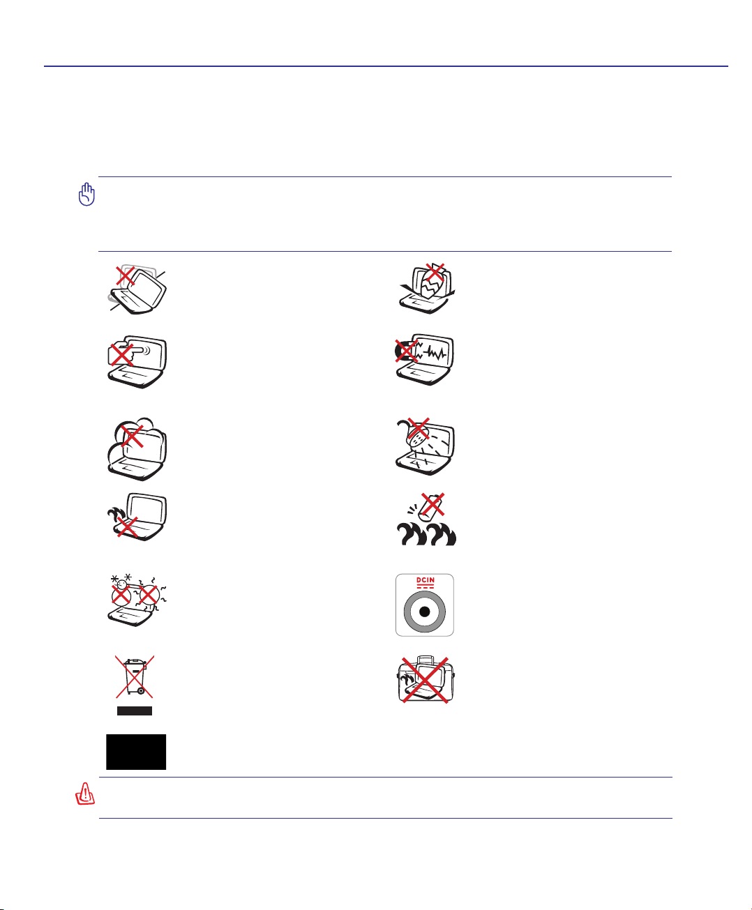
DO NOT expose to or use near liquids,
rain, or moisture. DO NOT use the
modem during an electrical storm.
DO NOT expose to dirty or dusty en-
vironments. DO NOT operate during
a gas leak.
SAFE TEMP: This Notebook PC
should only be used in environments
with ambient temperatures between
5°C (41°F) and 35°C (95°F)
Battery safety warning:
DO NOT throw the battery in re.
DO NOT short circuit the contacts.
DO NOT disassemble the battery.
DO NOT expose to strong magnetic
or electrical elds.
DO NOT place on uneven or unstable
work surfaces. Seek servicing if the
casing has been damaged.
DO NOT place or drop objects on top
and do not shove any foreign objects
into the Notebook PC.
DO NOT press or touch the display
panel. Do not place together with
small items that may scratch or enter
the Notebook PC.
DO NOT leave the Notebook PC on
your lap or any part of the body in
order to prevent discomfort or injury
from heat exposure.
DO NOT throw the Notebook PC
in municipal waste. Check local
regulations for disposal of electronic
products.
DO NOT carry or cover a Notebook
PC that is powered ON with any ma-
terials that will reduce air circulation
such as a carrying bag.
INPUT RATING: Refer to the rating
label on the bottom of the Notebook
PC and be sure that your power adapter
complies with the rating.
<000>
(1)
(See end of Section 4 for denition)
Models with 3G(1):Produces radio wave emissions that may cause electrical interferences
and must be used in places that do not prohibit such devices. Take precautions while using.
WARNING! The 3G function needs to be switched OFF in areas with potentially explosive atmo-
spheres such as petrol (gas) stations, chemical storage depots, and blasting operations.

8
1Introducing the Notebook PC
CAUTION! There are three main types of airport security devices: X-ray machines
(used on items placed on conveyor belts), magnetic detectors (used on people walking
through security checks), and magnetic wands (hand-held devices used on people or
individual items). You can send your Notebook PC and diskettes through airport X-ray
machines. However, it is recommended that you do not send your Notebook PC or
diskettes through airport magnetic detectors or expose them to magnetic wands.
Charge Your Batteries
If you intend to use battery power, be sure to fully charge your battery pack and any optional battery
packs before going on long trips. Remember that the power adapter charges the battery pack as long as
it is plugged into the computer and an AC power source. Be aware that it takes much longer to charge
the battery pack when the Notebook PC is in use.
Airplane Precautions
Contact your airline if you want to use the Notebook PC on the airplane. Most airlines will have restric-
tions for using electronic devices. Most airlines will allow electronic use only between and not during
takeoffs and landings.
Transportation Precautions
To prepare the Notebook PC for transport, you should turn it OFF and disconnect all external peripher-
als to prevent damage to the connectors. The hard disk drive’s head retracts when the power is turned
OFF to prevent scratching of the hard disk surface during transport. Therefore, you should not transport
the Notebook PC while the power is still ON. Close the display panel and check that it is latched securely
in the closed position to protect the keyboard and display panel.
CAUTION: The Notebook PC’s surface is easily dulled if not properly cared for. Be
careful not to rub or scrape the Notebook PC surfaces.
Cover Your Notebook PC
Purchase a carrying bag to protect the Notebook PC from dirt, water, shock, and scratches.

9
Introducing the Notebook PC 1
Preparing your Notebook PC
These are only quick instructions for using your Notebook PC. Read the later pages for detailed informa-
tion on using your Notebook PC.
1. Install the battery pack 2. Connect the AC Power Adapter
IMPORTANT! When opening, do not force
the display panel down to the table or else
the hinges may break! Never lift the Note-
book PC by the display panel!
E-SATA/
12
3
3. Open the Display Panel 4. Turn ON the Notebook PC
The power switch turns ON and OFF the Notebook
PC or putting the Notebook PC into sleep or hiber-
nation modes.Actual behavior of the power switch
can be customized in Windows Control Panel >
Power Options > System Settings.
1.3
MEGA
PIXELS

10
1Introducing the Notebook PC
<000>

11
2. Knowing the Parts
Basic sides of the Notebook PC
NOTE: Photos and icons in this manual are used for artistic purposes only and do not
show what is actually used in the product itself.
<000>

12
2Knowing the Parts
Top Side
Refer to the diagram below to identify the components on this side of the Notebook PC.
NOTE: The keyboard will be different for each territory.
2
1
1
11
12
9
3
6
5
4
7
8
10
2
Camera Indicator
The camera indicator shows when the built-in camera is in use. The camera may be auto-activated
by supported software.
Multi-Position Camera
The built-in camera allows picture taking or video recording. Can
be used with video conferencing and other interactive applications.
CAUTION: The lens can be adjusted facing forward or facing back-
ward but the lens can only ip through the bottom. Do not rotate the lens upward past 35 degrees.
Front
Back

13
Knowing the Parts 2
3
4
5
7
8
9
10
Power Switch
The power switch allows powering ON and OFF the Notebook PC and recovering from STD.
Use the switch once to turn ON and once to turn OFF the Notebook PC. In Windows XP, this
button can also be used to safely turn OFF the Notebook PC. The power switch only works
when the display panel is opened.
Instant Keys
Instant keys allow you to launch frequently used applications with one push of a button.
Details are described in section 3.
Audio Speakers
The built-in stereo speaker system allows you to hear audio without additional attachments.
The multimedia sound system features an integrated digital audio controller that produces
rich, vibrant sound (results improved with external stereo headphones or speakers). Audio
features are software controlled.
11
Status Indicators (front)
Status indicators represent various hardware/software conditions. See indicator details in section 3.
Status Indicators (top)
Status indicators represent various hardware/software conditions. See indicator details in section 3.
Keyboard
The keyboard provides full-sized keys with comfortable travel (depth at which the keys
can be depressed) and palm rest for both hands. Two Windows function keys are provided
to help ease navigation in the Windows operating system.
Microphone (Built-in)
The built-in mono microphone can be used for video conferencing, voice narrations, or simple
audio recordings.
12
6
Touchpad and Buttons
The touchpad with its buttons is a pointing device that provides the same functions as a desk-
top mouse. A software-controlled scrolling function is available after setting up the included
touchpad utility to allow easy Windows or web navigation.
Display Panel
The Notebook PC uses an active matrix TFT LCD, which provides excellent viewing like
that of desktop monitors. Unlike traditional desktop monitors, the LCD panel does not pro-
duce any radiation or ickering, so it is easier on the eyes. Use a soft cloth without chemical
liquids (use plain water if necessary) to clean the display panel.
Fingerprint Scanner (on selected models)
The built-in ngerprint scanner allows use of security software using your ngerprint as
your identication key.

14
2Knowing the Parts
Bottom Side
Refer to the diagram below to identify the components on this side of the Notebook PC.
NOTE: The bottom side may vary in appearance depending on model.
NOTE: The battery pack size will vary depending on model.
<000>
1
Battery Lock - Spring
The spring battery lock is used to keep the battery pack secured. When the battery pack is in-
serted, it will automatically lock. To remove the battery pack, this spring lock must be held in
the unlocked position.
CD/DVD
1 32
7
5
4
6
9
8
10
WARNING! The bottom of the Notebook PC can get very hot. Be careful when handling
the Notebook PC while it is in operation or recently been in operation. High tempera-
tures are normal during charging or operation. Do not use on soft surfaces such as
beds or sofas which may block the vents. DO NOT PUT THE NOTEBOOK PC ON YOUR
LAP OR OTHER PARTS OF THE BODY TO AVOID INJURY FROM THE HEAT.

15
Knowing the Parts 2
<000>
2
3
4
8
6
7
5
10
Shutdown Button (Emergency)
In case your operating system cannot properly turn OFF or restart, the shutdown button can
be pressed with a straightened paper clip to shutdown the Notebook PC.
Battery Lock - Manual
The manual battery lock is used to keep the battery pack secured. Move the manual lock to the
unlocked position to insert or remove the battery pack. Move the manual lock to the locked posi-
tion after inserting the battery pack.
Memory (RAM) Compartment
The memory compartment provides expansion capabilities for additional memory.Additional memory
will increase application performance by decreasing hard disk access. The BIOS automatically detects
the amount of memory in the system and congures CMOS accordingly during the POST (Power-On-
Self-Test) process.Thereisnohardwareorsoftware(includingBIOS)setuprequiredafterthememoryis
installed. Visit an authorized service center or retailer for information on memory upgrades for your Notebook PC. Only pur-
chase expansion modules from authorized retailers of this Notebook PC to ensure maximum compatibility and reliability.
Hard Disk Drive Compartment
The hard disk drive is secured in a compartment. Visit an authorized service center or retailer for
information on hard disk drive upgrades for your Notebook PC. Only purchase hard disk drives
from authorized retailers of this Notebook PC to ensure maximum compatibility and reliability.
Battery Pack
The battery pack is automatically charged when the Notebook PC is connected to an AC power source
and maintains power to the NotebookPCwhenACpower isnot connected.Thisallows use whenmoving
temporarily between locations. Battery time varies by usage and by the specications for this Notebook
PC. The battery pack cannot be disassembled and must be purchased as a single unit.
9
Cooling Fan
The cooling fan removes excess heat depending on temperature threshold settings.
IMPORTANT! Make sure that paper, books, clothing, cables, or other objects
do not block any of the air vents or else overheating may occur.
Module Lock
The Notebook PC has a user replaceable module. Visit an authorized dealer for com-
patible modules for this Notebook PC.
Optical Drive Module
The Notebook PC has an upgradeable optical drive module. Visit an authorized dealer
for upgrades.
CD/
DVD
Power Station Connector
The Power Station connector allows the Notebook PC to interface with the optional
Power Station.

16
2Knowing the Parts
1
5
<000>
ExpressCard Slot
One 26pin Express card slot is available to support one ExpressCard/34mm or one
ExpressCard/54mm expansion card. This new interface is faster by using a serial bus
supporting USB 2.0 and PCI Express instead of the slower parallel bus used in the PC
card slot. (Not compatible with previous PCMCIA cards.)
3
4
2
Right Side
Refer to the diagram below to identify the components on this side of the Notebook PC.
1 2 3 6 874 5 9 10
E-SATA/
Flash Memory Slot
Normally an external memory card reader must be purchased separately in order to use
memory cards from devices such as digital cameras, MP3 players, mobile phones, and
PDAs. This Notebook PC has a built-in high-speed memory card reader that can conveniently
read from and write to many ash memory cards as mentioned later in this manual.
SPDIF Output Jack
This jack provides connection to SPDIF (Sony/Philips Digital Interface) compliant de-
vices for digital audio output. Use this feature to turn the Notebook PC into a hi- home
entertainment system.
Headphone Output Jack
The stereo headphone jack (1/8 inch) is used to connect the Notebook PC’s audio out signal to
amplied speakers or headphones. Using this jack automatically disables the built-in speakers.
Combo
Microphone Input Jack
The mono microphone jack (1/8 inch) can be used to connect an external microphone or output
signals from audio devices. Using this jack automatically disables the built-in microphone. Use
this feature for video conferencing, voice narrations, or simple audio recordings.
2.0
E-SATA & USB (2.0/1.1) Combo Port (on selected models)
External SATA or eSATA allows external connection of Serial-ATA devices
originally designed for use inside the computer. It is up to six times faster than
existing USB 2.0, & 1394 for external storage solutions and is also hot plug-
gable using shielded cables and connectors up to two meters. (See “USB Port”
on other sides for description.)
E-SATA

17
Knowing the Parts 2
8
9
IEEE1394 Port (on selected models)
IEEE1394 is a high speed serial bus like SCSI but has simple connections and hot-
plugging capabilities like USB. The interface IEEE1394 has a bandwidth of 100-400
Mbits/sec and can handle up to 63 units on the same bus. IEEE1394 is also used in
high-end digital equipment and should be marked “DV” for Digital Video port.
7
6
<000>
2.0
USB Port (2.0/1.1) (on selected models)
The USB (Universal Serial Bus) port is compatible with USB 2.0 or USB 1.1 devices such as
keyboards, pointing devices, cameras, hard disk drives, printers, and scanners connected in a
series up to 12Mbits/sec (USB 1.1) and 480Mbits/sec (USB 2.0). USB allows many devices to
run simultaneously on a single computer, with some peripherals acting as additional plug-in sites or
hubs. USB supports hot-swapping of devices so that most peripherals can be connected or disconnected
without restarting the computer.
Modem Port
The RJ-11 modem port with two pins is smaller than the RJ-45 LAN port and supports
a standard telephone cable. The internal modem supports up to 56K V.90 transfers. The
built-in connector allows convenient use without additional adapters.
IMPORTANT! The built-in modem does not support the voltage used in digital
phone systems. Do not connect the modem port to a digital phone system or
else damage will occur to the Notebook PC.
10
Power (DC) Input
The supplied power adapter converts AC power to DC power for use with this jack. Power sup-
plied through this jack supplies power to the Notebook PC and charges the internal battery pack.
To prevent damage to the Notebook PC and battery pack, always use the supplied power
adapter. CAUTION: MAY BECOME WARM TO HOT WHEN IN USE. BE SURE
NOT TO COVER THE ADAPTER AND KEEP IT AWAY FROM YOUR BODY.
Cooling Fan
The cooling fan removes excess heat depending on temperature threshold settings.
IMPORTANT! Make sure that paper, books, clothing, cables, or other objects
do not block any of the air vents or else overheating may occur.

18
2Knowing the Parts
2
3
4
1
5
Left Side
Refer to the diagram below to identify the components on this side of the Notebook PC.
HDMI
12 3 54 6 7 8
2.0
USB Port (2.0/1.1) (on selected models)
The USB (Universal Serial Bus) port is compatible with USB 2.0 or USB 1.1 devices such as
keyboards, pointing devices, cameras, hard disk drives, printers, and scanners connected in a
series up to 12Mbits/sec (USB 1.1) and 480Mbits/sec (USB 2.0). USB allows many devices to
run simultaneously on a single computer, with some peripherals acting as additional plug-in sites or
hubs. USB supports hot-swapping of devices so that most peripherals can be connected or disconnected
without restarting the computer.
HDMI Port
HDMI (High-Denition Multimedia Interface) is an uncompressed all-digital audio/
video interface between any audio/video source, such as a set-top box, DVD player,
and A/V receiver and an audio and/or video monitor, such as a digital television
(DTV). Supports standard, enhanced, or high-denition video, plus multi-channel
digital audio on a single cable. It transmits all ATSC HDTV standards and supports 8-
channel digital audio, with bandwidth to spare to accommodate future enhancements or requirements.
HDMI
LAN Port
The RJ-45 LAN port with eight pins is larger than the RJ-11 modem port and supports a
standard Ethernet cable for connection to a local network. The built-in connector allows
convenient use without additional adapters.
TV-Out Port
The TV-Out port is an S-Video connector that allows routing the Notebook PC’s display
to a television or video projection device. You can choose between simultaneously or
single display. Use an S-Video cable (not provided) for high quality displays or use the
provided RCA to S-Video adapter for standard video devices. This port supports both
NTSC and PAL formats.
Display (Monitor) Output
The 15-pin D-sub monitor port supports a standard VGA-compatible device such as a monitor
or projector to allow viewing on a larger external display.

19
Knowing the Parts 2
Optical Drive Emergency Eject (location varies by model)
The emergency eject is used to eject the optical drive tray in case the electronic eject does
not work. Do not use the emergency eject in place of the electronic eject.
Optical Drive
The Notebook PC comes in various models with different optical drives. The Notebook
PC’s optical drive may support compact discs (CD) and/or digital video discs (DVD) and
may have recordable (R) or re-writable (RW) capabilities. See the marketing specica-
tions for details on each model.
Optical Drive Electronic Eject
The optical drive eject has an electronic eject button for opening the tray. You can also eject
the optical drive tray through any software player or by right clicking the optical drive in
Windows “Computer” and selecting Eject.
8
7
6

20
2Knowing the Parts
Front Side
Refer to the diagram below to identify the components on this side of the Notebook PC.
1
Infrared Port (IrDA) (front side or right side depending on model)
The infrared (IrDA) communication port allows convenient wireless data communication with
infrared-equipped devices or computers. This allows easy wireless synchronization with PDAs
or mobile phones and even wireless printing to printers. If your ofce supports IrDA networking,
you can have wireless connection to a network anywhere provided there is a direct line of sight to
an IrDA node. Small ofces can use IrDA technology to share a printer between several closely
placed Notebook PCs and even send les to each other without a network.
1
Table of contents
Other Asus Laptop manuals

Asus
Asus E17820 Guide

Asus
Asus Eee PC 900HD Series Operating manual

Asus
Asus G71G - Q2 - Core 2 Quad GHz User manual

Asus
Asus C403NA FQ0019 User manual

Asus
Asus ROG G Series Guide

Asus
Asus ROG Strix GL503VM-GZ128T User manual

Asus
Asus Eee PC X101H User manual

Asus
Asus FX504GM EN102T Guide

Asus
Asus S551LA Guide

Asus
Asus GX700V Guide

Asus
Asus Z96J Installation manual

Asus
Asus A55A User manual

Asus
Asus F3P Instructions for use

Asus
Asus M9A Instructions for use

Asus
Asus G51Jx User manual

Asus
Asus G70SG-A1 Instructions for use

Asus
Asus E10750 Guide

Asus
Asus ROG Zephyrus G14 User manual

Asus
Asus S7F User manual

Asus
Asus ROG G501VW FW106T Guide