Atag KD80122AF User manual

Installation instructions
Refrigerators and freezers for integrated use, door-on-door
KD80122AF
KD80140AF
KD80140BF
KD80178AF
KD80140CD
KD80178CD
KD80102AD
KD80140AD
700005496000

Contents
1 General safety information................................... 2
2 Transporting the appliance................................... 2
3 Installing the appliance......................................... 2
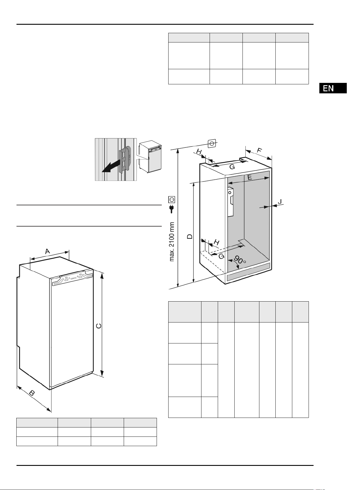
4 Appliance dimensions........................................... 3
5 Recess dimensions............................................... 3
6 Unit door................................................................. 4
7 Ventilation of the kitchen unit............................... 4
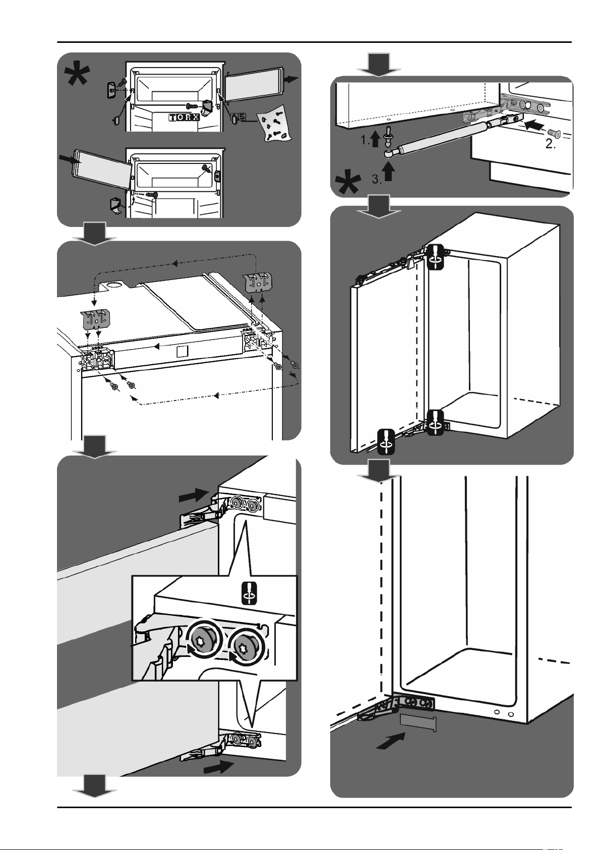
8 Changing over door hinges.................................. 5
9 Installing the appliance in the recess.................. 5
10 Disposing of packaging........................................ 5
11 Connecting the appliance..................................... 6
Illustrated installation instructions...................... 7
The manufacturer works constantly on the further development
of all the types and models. Therefore please understand that
we have to reserve the right to make design, equipment and
technical modifications.
To get to know all the benefits of your new appliance, please
read the information contained in these instructions carefully.
The instructions apply to several models. Differences may
occur. Text relating only to specific appliances is marked with
an asterisk (*).
Instructions for action are marked with a , the results of
action are marked with a .
1 General safety information
-Only install, connect and dispose of the appli-
ance according to the instructions. Take
particular note of “Recess dimensions” (see 5)
and “Ventilation of the kitchen unit” (see 7) .
-The socket must be easily accessible so that
the appliance can be quickly disconnected
from the supply in an emergency. It must be
outside the area of the rear of the appliance.
DANGER identifies a situation involving direct
danger which, if not obviated, may
result in death or severe bodily
injury.
WARNING identifies a dangerous situation
which, if not obviated, may result in
death or severe bodily injury.
CAUTION identifies a dangerous situation
which, if not obviated, may result in
minor or medium bodily injury.
NOTICE identifies a dangerous situation
which, if not obviated, may result in
damage to property.
Note identifies useful information and tips.
2 Transporting the appliance
CAUTION
Risk of injury and danger of damage as a result of incorrect
transport!
uTransport the appliance in a packed condition.
uTransport the appliance upright.
uDo not transport the appliance without assistance.
3 Installing the appliance
WARNING
Risk of fire due to short circuit!
If the mains cable/connector of the appliance or of another
appliance touch the rear of the appliance, the mains cable/
connector may be damaged by the appliance vibrations,
leading to a short circuit.
uStand the appliance so that it is not touched by connectors
or main cables.
uDo not plug the appliance or any others into sockets located
near the rear of the appliance.
WARNING
Fire hazard due to dampness!
If live parts or the mains lead become damp this may cause
short circuits.
uThe appliance is designed for use in enclosed areas. Do not
operate the appliance outdoors or in areas where it is
exposed to splash water or damp conditions.
uOnly use the appliance when it is installed.
WARNING
Fire hazard due to refrigerant!
The refrigerant R 600a is environmentally friendly but flam-
mable. Escaping refrigerant may ignite.
uDo not damage the piping of the refrigeration circuit.
WARNING
Fire hazard and danger of damage!
uDo not place appliances emitting heat e.g. microwaves,
toasters etc. on the appliance!
NOTICE
Risk of damage due to condensate!
uDo not install the appliance directly alongside a further
refrigerator/freezer.
NOTICE
Risk of damage due to condensation!
When stacking multiple appliances there is a risk of conden-
sation damage.
uDo not stack refrigerators or freezers.
WARNING
Blocked ventilation openings pose a risk of fire and damage!
uAlways keep the ventilation openings clear. Always ensure
that the appliance is properly ventilated!
qIn the event that the appliance is damaged, contact the
supplier immediately before connecting to the mains.
General safety information
2 * Depending on model and options

qThe floor at the site must be flat and level.
qDo not install the appliance in a location where it is exposed
to direct radiation of the sun, next to a cooker, heater and
similar.
qDo not install the appliance alone: it is best to work together
with two or more people.
qThe more R 600a refrigerant there is in the appliance, the
larger the room in which the appliance is standing needs to
be. In rooms that are too small, a flammable mix of gas and
air may be created if there is a leak. According to the EN 378
standard, every 11 g of R 600a refrigerant requires at least
1 m3 space in the room for the appliance. The amount of
refrigerant in your appliance is on the type plate inside the
appliance.
qIf the appliance is installed in a very damp environment,
condensed water may form on the outside of the appliance.
Always make sure that there is good ventilation - both at air
inlet and outlet - at the site of installation.
uPull off red transport lock.
After installation:
uRemove protective films, adhesive tapes and transport lock
parts etc.
Note
uClean the appliance (see Operating Instructions,
Chapter "Cleaning the appliance").
4 Appliance dimensions
Fig. 1
A (mm) B (mm) C (mm)
KD80102AD 559 544 1022
KD80122AF 559 544 1218
A (mm) B (mm) C (mm)
KD80140AF,
KD80140BF,
KD80140CD,
KD80140AD
559 544 1395
KD80178AF,
KD80178CD
559 544 1770
5 Recess dimensions
The appliance is built-in and therefore completely enclosed by
a kitchen unit. The kitchen unit concerned must be built exactly
to the prescribed dimensions and allow for sufficient ventilation,
both at air inlet and outlet, to ensure proper appliance opera-
tion.
Fig. 2
D
(mm
)
E
(mm
)
F (mm) G
(mm
)
H
(mm
)
J
(mm
)
KD80102AD 1024
—
1040
560
—
570
min.
550, 560
recom-
mended
min.
500
min.
40
max.
19
KD80122AF 1220
—
1236
KD80140AF,
KD80140BF,
KD80140CD
,
KD80140AD
1397
—
1413
KD80178AF,
KD80178CD
1772
—
1788
The specified energy consumption applies to a unit depth of
560 mm. The appliance will work properly at a unit depth of 550
mm, but at a slightly higher energy consumption.
uCheck the wall thickness of the adjoining cabinets: it must
be min. 16 mm thick.
Appliance dimensions
* Depending on model and options 3

uOnly install the appliance in robust, stable kitchen units.
Secure the units against tipping.
uAlign the kitchen unit using a spirit level and marking square
and if necessary compensate with shims.
uEnsure that the floor and walls of the unit are at right angles
to one another.
6 Unit door
-One door is required for the kitchen unit.
-The door must be minimum 16 mm and maximum 19 mm
thick.
-There must be a gap of minimum 3 mm width between the
door and the unit door located above it (if one exists).
-The width of the unit door depends on the style of the
kitchen and the gap size between the door panels of the
cabinet. Generally, there should remain a vertical gap of
3 mm between the unit doors.
-If other cabinets are present, the top edge of the unit door
should be on a level with the doors of the adjoining units.
-The unit door must be planar and mounted stress-free.
NOTICE
Risk of damage from over-heavy unit door!
If the unit door is too heavy, damage to the hinges and resulting
impairment of function cannot be excluded.
uBefore mounting the unit door, make sure that the door does
not exceed the approved unit door weight.
Appliance model Maximum cabinet
door weight (kg)
KD80102AD 13
KD80122AF 19
KD80140AD, KD80140AF,
KD80140BF, KD80140CD
21
KD80178AF, KD80178CD 26
7 Ventilation of the kitchen unit
Fig. 3
-There must be an effective ventilation shaft of at least
200 cm2 per appliance at the air inlet
Fig. 3 (A)
and outlet
Fig. 3 (B)
vent.
-The principle applies that the larger the ventilation shaft, the
more energy-saving the operation of the appliance.
-The depth of the ventilation shaft at the back of the cabinet
must be min. 40 mm.
Fig. 4
-The upper ventilation shaft can either be positioned directly
above the appliance with an optional ventilation grille
Fig. 4 (C)
, close to the ceiling above the unit
Fig. 4 (D)
or as
an air outlet opening in a false ceiling
Fig. 4 (E)
.
Unit door
4 * Depending on model and options

8 Changing over door hinges
CAUTION
Risk of injury if soft stop contracts!
uCarefully remove the soft stop mechanism.
CAUTION
Risk of injury if hinges fold!
uLeave hinges open.
WARNING
Risk of injury due to the door dropping out!
If the fastening parts are not screwed into place firmly enough,
the door may drop out. This may lead to severe injuries. What is
more, the door may not close and therefore the appliance may
fail to cool properly.
uScrew the hinges and the ball journal of the soft stop mecha-
nism firmly into place, with 4 Nm.
uScrew the holder of the soft stop mechanism firmly into
place, with at least 3 Nm.
uCheck all of the screws and retighten if necessary.
Note
The door hinges can only be changed over if there is sufficient
space towards the top to pull out the hinge mounting bracket
and to mount it again on the other side. This is generally not the
case after installation in the recess.
uChange the hinges over before the appliance is installed in
the recess.
There is a risk of injury during this stage! Please
observe the safety instructions!
The instructions apply to several models. Only carry
out this step if it is relevant for your appliance.
Choose between the alternatives given.
Loosen the screws only, do not undo them all the way.
Check the screws and tighten if necessary.
uWhile changing over the door hinges, observe the safety
instructions above and also the information in the symbols
key.
Change the hinges over as shown at the end
of the book.
9 Installing the appliance in the
recess
WARNING
Fire hazard from short-circuiting!
uWhen pushing the appliance into the recess, take care not to
crush, jam or damage the mains power cable.
uDo not operate the appliance with a defective mains power
cable.
NOTICE
Risk of damaging the hinges!
If when being pushed the appliance is held by the door, the
hinges could be damaged.
uWhen pushing or otherwise moving the appliance, always
hold it by the main body.
For installation in the recess, the following accessories
are available from Customer Service:
Set for limiting the door opening angle
to 90°
Set for fitting split furniture front
panels
Set with covers for concealed hinges
There is a risk of injury during this stage! Please
observe the safety instructions!
The instructions apply to several models. Only carry
out this step if the appliance is equipped with the
corresponding feature.
Choose between the alternatives given.
Loosen the screws only, do not undo them all the way.
Check the screws and tighten if necessary.
uPlease take note of the information in the symbols key
during installation.
Install the appliance in the recess as shown at
the end of the booklet.
10 Disposing of packaging
WARNING
Danger of suffocation due to packing material and plastic film!
uDo not allow children to play with packing material.
Changing over door hinges
* Depending on model and options 5

The packaging is made of recyclable materials:
-corrugated board/cardboard
-expanded polystyrene parts
-polythene bags and sheets
-polypropylene straps
-nailed wooden frame with polyethylene panel*
uTake the packaging material to an official collecting point.
11 Connecting the appliance
NOTICE
Failure to connect properly
Damage to the electronics.
uDo not use a standalone inverter.
uDo not use an energy saving plug.
WARNING
Failure to connect properly
Fire.
uDo not use an extension cable.
uDo not use distributor blocks.
The type of current (alternating current) and voltage at the
installation site have to conform with the data on the type plate
(see Appliance at a glance).
The socket must be properly earthed and fused. The tripping
current for the fuse must be between 10 A and 16 A.
The socket must be easily accessible so that the appliance can
be quickly disconnected from the supply in an emergency. It
must be outside the area of the rear of the appliance.
uCheck the electrical connection.
uPlug in the power plug.
Connecting the appliance
6 * Depending on model and options

7

8 * Depending on model and options

9

10 * Depending on model and options

11

12 * Depending on model and options

13

14 * Depending on model and options

15

gba 7086392 - 00
ATAG - www.atag.nl
This manual suits for next models
7
Table of contents
Other Atag Refrigerator manuals

Atag
Atag KS30122BUU/A03 User manual

Atag
Atag KD85122AF User manual

Atag
Atag KU2590A User manual

Atag
Atag KS24178B User manual

Atag
Atag KD63140B/A01 User manual

Atag
Atag KD8140CD User manual

Atag
Atag Refrigerator User manual

Atag
Atag KA2411R/A02 User manual

Atag
Atag KS30122AUU/A01 User manual

Atag
Atag KU1090BUU User manual