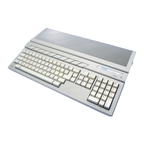
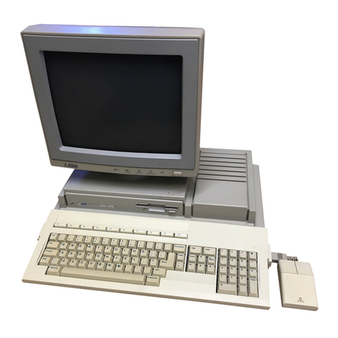
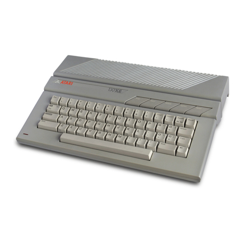
Atari 520STE Quick start guide


II
Atari STe 520/1040
Computer Field Service Manual
Part Number: C302481–001 Rev A
August 1991

III
TABLE OF CONTENTS
SECTION ONE: INTRODUCTION ...................................................................................1
1.0 Overview ..........................................................................................................1
1.1 Main Components ............................................................................................1
1.2 Case Design ....................................................................................................1
1.3 Power Supply ...................................................................................................3
1.4 Negative Supplies ............................................................................................3
SECTION TWO. THEORY OF OPERATION .................................................................. 4
2.0 Overview ..........................................................................................................4
2.1 Main System .................................................................................................... 4
2.2 Audio/Video Subsystem ...................................................................................4
2.3 InputlOutput Subsystems .................................................................................5
2.4 Microprocessing Unit ........................................................................................5
2.5 GSTMCU ..........................................................................................................5
2.6 Main Memory ................................................................................................... 6
2.7 Direct Memory Access .....................................................................................7
2.8 Multi–Function Peripheral Control ....................................................................7
2.9 Audio/Viideo Subsystem ..................................................................................8
2.10 Digitized Sound ................................................................................................10
2.11 Genlock and the STE .......................................................................................10
2.12 Input/Output Subsystems .................................................................................11
2.13 System Startup ................................................................................................ 21
2.14 System Errors .................................................................................................. 22
SECTION THREE: TESTING .......................................................................................... 24
3.1 Overview ..........................................................................................................24
3.2 Test Configuration ............................................................................................25
3.3 Troubleshooting a Dead Unit ........................................................................... 25
3.4 Diagnostic Cartridge ....................................................................................... 26
3.5 Power Up Sequence ....................................................................................... 26
3.6 Test Menu ....................................................................................................... 28
3.7 RAM Test ........................................................................................................ 28
3.8 ROM Test ........................................................................................................ 29
3.9 Color Test ........................................................................................................ 29
3.10 Keyboard Test ................................................................................................. 30
3.11 MIDI Tests ........................................................................................................31
3.12 RS232 Tests .................................................................................................... 31
3.13 Audio Test ........................................................................................................32
3.14 Timing Tests .................................................................................................... 33
3.15 DMA Tests ....................................................................................................... 34
3.16 FIoppy Disk Tests ............................................................................................ 34
3.17 Printer and Joystick Port Tests ........................................................................ 36
3.18 Monochrome Monitor .......................................................................................37
3.19 Hard Disk WriteIRead ...................................................................................... 37
3.20 Graphics Chip BLiT ..........................................................................................38
3.21 Error Codes (quick Reference)......................................................................... 38
SECTION FOUR: DISASSEMBLY/ASSEMBLY …………………………………………… 43
4.1 STE Disassembly .............................................................................................43
4.2 STE Reassembly ............................................................................................. 44
IV
SECTION FIVE: SYMPTOM CHECKLIST ………………………………………………….. 45
5.1 Display Problems .............................................................................................45
5.2 Disk Drive Problems .........................................................................................45
5.3 Keyboard Problems ..........................................................................................46
5.4 MIDI Problems ................................................................................................. 46
5.5 RS232 Problems ..............................................................................................46
5.6 Printer Port Problems .......................................................................................46
5.7 Hard Disk Port Problems ..................................................................................46
5.8 DMA Sound ......................................................................................................46
SECTION SIX: DIAGNOSTIC FLOWCHARTS ………………………………………….…..47
6.1 Replacement Procedures .................................................................................47
6.2 Handling of Integrated Circuits .........................................................................47
SECTION SEVEN: PARTS LIST ..................................................................................... 52
SECTION EIGHT: GLOSSARY ....................................................................................... 56
SECTION NINE: SCHEMATICS AND SILKSCREENS ...................................................58

V
Reproduction of all or any portions of this manual is not allowed without the specific
written consent of Atari Corporation.
Every effort has been made to ensure the accuracy of the product documentation in
this manual. However, because Atari Corporation is constantly improving and
updating its computer hardware and software, it is unable to guarantee the accuracy
of printed material after the date of publication and disclaims liability for changes,
errors. or omissions.
These documents are for repair service information only. Part numbers are for
reference only. Only parts on current dealer parts lists are available. No license is
given for any use by the possession of these documents and may not be reproduced
in any form without the written approval of Atari Corporation.
Atari, the Atari logo, STE, TOS, BLiTTER , SM124, SC1224, SF314, SF354,
PCF554, SLM804, CDAR504, Atari BASIC, and Atari SFP–004 are trademarks or
registered trademarks of Atari Corporation. Centronics is a registered trademark of
Centronics Data Computer Corporation. GEM and GEM Desktop are trademarks or
registered trademarks of Digital Research, Inc. MS–DOS is a registered trademark of
Microsoft Corporation. Epson is a registered trademark of Seiko–Epson Corporation.
VT and DEC are registered trademarks of Digital Equipment Corporation.
Copyright © 1991, Atari Corporation
Sunnyvale, CA 94089–1302
All rights reserved.

1
SECTION ONE: INTRODUCTION
1.0 OVERVIEW
The 520STE and 1040STE are designed as integrated units with keyboard,
processor, memory, and I/O control in one package. The 520STE has 520 kbytes
(524.280 bytes ) of RAM, and the 1040STE has 1040 kbytes (1,048,568 bytes) of
RAM. The 1040STE and 520STE both have a built–in 1 megabyte floppy disk drive
(unformatted). Both the 520STE and 1040STE come with a modulator for TV output.
The 520STE and 1040STE both have the power supply integrated into the case.
1.1 MAIN COMPONENTS
•524K RAM (1048K for the 1040STE)
•Main Board with modulator (except French Peritel)
•Keyboard Assembly
•RF Shield (upper and lower) and Power Supply
•Plastic Case (upper and lower)
•Mouse
•Power Supply
•Disk Drive
1.2 CASE DESIGN
The 520STE and the 1040STE are nearly identical. The upper case has openings for
the keyboard and a lens for both the power indicator LED (front left corner) and the
Disk Drive Activity LED (mid right side). (see Fig. 1–1)
Figure 1–1: 520STE Upper Case

2
Figure 1–2. 1040STE Upper Case
The left side panels of both machines have slots for the expansion cartridge, two
MIDI ports and two game controllers.
Figure 1–3. STE Left Side Panel
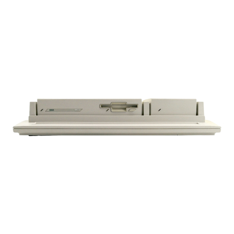
The right side panel has a slot for the floppy disk drive.
Figure 1–4. STE Right Side Panel
The STE back panel contains (left to right) the modem (RS232) connector, printer
connector, hard disk/DMA connector, external floppy disk connector, television
output, monitor connector, power switch, stereo output (right and left), AC power
input, and reset button. (see Fig. 1–5)

3
Figure 1–5. STE Back Panel
1.3 POWER SUPPLY
The 520STE and 1040STE have an integral switching power supply providing +5V
and +12V. There is a 2A fuse. Voltage should be adjusted to 5.1V. The power supply
has overcurrent protection; if the fuse is blown, a catastrophic failure is likely, such
as shorted primary
Power Supply Rating
Current out: 3A at 5V, 0.9A at +12V
Max. power in: 33.5W
Typical (in system) Demand.
Typical current: 1.75A at 5V, 86 mA at + 12V
Max. current: 2.2A at +5V, 90 mA at +12 (during disk access)
1.4 NEGATIVE SUPPLIES
The STE motherboard contains two small switching voltage regulators (the TL497 or
equivalent) that are used to provide additional voltages.
0204 is used to generate the positive and negative voltages for the RS232C line
drivers. These voltages are normally ±12 VDC.
U205 is used to generate a –5 VDC supply for the audio subsection. This output is
heavily filtered to reduce the switching noise that might otherwise appear in the
audio output.

4
SECTION TWO: THEORY OF OPERATION
2.0 OVERVIEW
The 520STE and 1040STE share a common architecture, using the same LSI chip
set. The most significant difference is the addition (to the 1040STE) of one bank of
512K of RAM, for a total of 1024K (1,048,568 bytes). Except for the additional RAM,
the differences between the 520STE and 1040STE are transparent to software. The
hardware can be considered as consisting of a main system (central processing unit
and support chips) and several Input/Output subsystems.
2.1 MAIN SYSTEM
•MC68000 running at 8 MHz
•256 kbyte ROM
•512/1024 kbyte RAM
•Direct Memory Access Support
•System Timing and Bus Control
•Interrupt Control
2.2 AUDIO/VIDEO SUBSYSTEM
The STE has bit–mapped video display, normally using 32,000 bytes of RAM,
relocatable anywhere in memory. There are three display modes available:
RGB, with the ability to be GenLocked:
1. 320 x 200 pixel, 16 color palette from 4096 selections
2. 640 x 200 pixel, 4 color palette from 4096 selections
Monochrome:
3. 640 x 400 pixel, monochrome monitor interface
2.2.1 Audio Output
The STE has a programmable sound chip and 8–bit stereo DMA at 4 playback
frequencies.
2.2.2 Television Interface
NTSC, PAL I and PAL B.

5
2.3 INPUT/OUTPUT SUBSYSTEMS
•Intelligent keyboard with 2 button mouse/joystick interface
•Parallel printer interface
•RS232C serial interface
•Floppy disk drive and connector for external drive
•Game controller ports
•Hard disk drive interface (ACSI)
•Musical instrument network communication: Musical Instrument Digital
Interface (MIDI)
2.4 MICROPROCESSING UNIT
The STE uses the Motorola MC68000 16–bit external/32–bit internal data bus. 24–bit
address bus microprocessor, running at 8 MHz.
2.5 GSTMCU
GSTMCU is such an important component that it is involved in nearly every operation in the
computer. The functions may be summarized as follows:
CLOCK DIVIDERS takes the 16 MHz clock and outputs 8 MHz, 4 MHz, and
500 kHz clocks.
VIDEO TIMING Blank, DE (Display Enable), Vsync and Hsync are used to generate
signals for the video display. There is a Read/Write register in GSTMCU which may
be written to configure for 50 or 60 Hz operation or 71 Hz monochrome operation
(done by the Operating System).
INTERRUPT PRIORITY interrupts from the MFP and video timing are coded into
four levels of priority on outputs IPLO and IPL1 to the 68000. These levels corres-
pond to no interrupts, MFP interrupts, VSYNC interrupt, HSYNC interrupt.
level 7 reserved
level 6 MFP
level 5 unused
level 4 VSYNC
level 3 unused
level 2 HSYNC
level 1 unused
SIGNAL AND BUS ARBITRATION GSTMCU decodes addresses to generate chip
selects to the 6850s, MFP, DMA Controller. Programmable Sound Generator,
Memory Controller, and ROMS. It receives signals from the MFP, DMA, Memory

6
Controller, to synchronize data transfer. It arbitrates the bus during DMA transfers to
prevent CPU and DMA devices from interfering with each other (see DMA below).
ILLEGAL CONDITION DETECTION GSTMCU asserts Bus Error (BERR) if certain
conditions are violated, such as writing to ROM, writing to system memory when the
processor is in user mode, or if no device responds within 64 cycles of the 8 MHz
clock (8Ns). For example, if the CPU tries to read from beyond the end of memory,
the Memory Controller will not assert DTACK, resulting in a bus error which will
terminate the memory cycle.
MEMORY CONTROLLER takes addresses from the address bus and converts to
Row Address Strobe (RAS) and Column Address Strobe (CAS). All RAM accesses
are controlled by this Atari proprietary chip, which is programmable for up to 4
Megabytes of memory. The Operating System determines how much memory is
present and configures the Memory Controller at power–up. The Memory Controller
refreshes the dynamic RAMs, loads the Video Shifter with display data, and gives or
receives data during direct memory access (DMA). The Memory Controller produces
all of the addresses for video, sound, and DMA on the multiplexed address bus.
These addresses never appear on the system address bus.
CHIP SELECTS Decodes addresses for RAM and ROM and asserts output signals
to enable these devices.
2.6 MAIN MEMORY
Main memory consists of 256 kbytes of ROM and one or two banks (512 kbyte each)
of dynamic RAM. In addition, the cartridge slot allows access to 128 kbytes of ROM.
All memory is directly addressable. The components of the memory system are:
ROM, RAM, GSTMCU and shifter. The Operating System resides mostly in ROM,
with optional segments loaded from disk into RAM.
Each bank of RAM in the STE is made up of a pair of 8–bit wide SIMMs to create the
16–bit wide system memory bus. All of the SIMMs in the system must be the same
size. It is not possible to mix 256 kbit SIMMs and 1 Mbit SIMMs in the same system.
All of the SIMMs used should have the same access time, which can be no greater
than 150 ns.
It is possible to use 9–bit wide SIMMs, with the hardware simply ignoring the ninth
bit.
RAM MEMORY MAP:
000008–000800 System Memory (privileged access)
000800–07FFFF Low Bank
080000–0FFFFF High Bank (1040 only)
Note: The first 8 bytes of ROM are mapped into addresses 0–7. These are reset
vectors which the 68000 uses on start–up.
The Operating System is located in two 128K x 8 ROM chips.
ROM MEMORY MAP.
E00000–E3FFFF

7
2. 7 DIRECT MEMORY ACCESS
A single direct memory access (DMA) channel is provided that is shared between
the internal floppy disk controller and external devices connected to the ACSI port.
Data can be transferred at up to 10 Megabits/sec (1.25 Megabytes/sec) across the
8–bit wide ACSI port.
For DMA to take place, the memory controller is programmed with the starting
address at the RAM buffer. The DMA controller is set up to select the source and the
number of 512 byte blocks to transfer, and then the FDC or external peripheral is
given the command to send or receive data. The entire block of data is then
transferred to or from memory
without intervention by the CPU. The FDC or peripheral generally asserts its interrupt
line to signal the completion of the transfer (and the availability of status information).
To access registers in the FDC or ACSI bus peripherals, the 68000 talks through the
DMA chip. The state of two address lines that are generated by the DMAC is set by
writing to the DMA control register. Then a 68000 read or write cycle causes the
corresponding cycle on the peripheral side of the DMAC.
2.8 MULTI–FUNCTION PERlPHERAL CONTROL
2.8.1 Interrupt Control
The 68901 MFP can generate up to 16 interrupts, 8 internally and 8 from external
sources. Each interrupt can be masked off or disabled by programming the MFP.
The 8 inputs are also directly readable by the CPU. When the MFP receives an
interrupt internally, if the interrupt is enabled, MFPINT will be driven low. When the
CPU is ready to respond, it signals interrupt acknowledge (FC2–FC0 high, A3–A1=6,
and R/W low) and GSTMCU will assert the MFPs IACK signal (interrupt
acknowledge). The MFP will assert DTACK and put a vector number on the data
bus, which the CPU will read and use to calculate the address of the interrupt
routine.
The interrupts controlled by the MFP are: monochrome monitor detect (MONOMON),
RS232 (including CTS, DCD, RI), disk (FDINT and HDINT), parallel port BUSY,
display enable (DE, equals the active part of a display line), 6850 IRQs for keyboard
and MIDI data, and MFP timers.
Not all I/O operations use interrupts. The CPU can also poll the MFP while waiting
for an operation to complete or to check the current status.
2.8.2 MFP Counter/Timers
The MFP clock runs at 2.4576 MHz. The MFP contains four timers:
Timer A Reserved for application software used in the original ST. In the STE, its
external event input is used to count DMA sound subsystem cycles.

8
Timer B External input can be used to count horizontal display lines.
Timer C Reserved for use by the operating system as a periodic interrupt (nominally
200 Hz when running TOS).
Timer D Baud rate generator for the MFP's RS232 port. Its output is used to drive
both the receiver and transmitter clock inputs. It will normally be
programmed to be 16 times the desired asynchronous baud rate.
2.9 AUDIO/VIDEO SUBSYSTEM
The video subsystem consists of the video display memory (an arbitrary block of
RAM starting on any word boundary), the GSTMCU, a graphics control chip (Video
Shifter), some discrete components to drive the video output, and an RF modulator.
The audio subsystem consists of a Programmable Sound Generator chip, DMA
sound circuit, and a programmable mixer (LMC 1992).
2.9.1 Video Shifter (GSTShifter)
There are 16 color palette registers in the shifter. All 16 may be used in low
resolution, 4 may be used in medium resolution, and only one is used in high
resolution (actually, only bit 0 of register 0 is used for inverse/normal video). Each
palette is programmed for 16 levels of intensity of red, blue, and green, so there are
16 x 16 x 16 = 4096 colors possible. For a given pixel, the color which is displayed is
taken from the palette pointed to by assembling the bits from each logical plane (see
description of video display memory below). The shifter will output the red, green and
blue levels specified by the palette. Note that there are four outputs for each color.
Each output is either on or off. Thus, the number of possible output levels is 2 to the
4th power = 16 levels. The four outputs are summed through a resistor network to
proportion the voltage level to give 16 equal steps. In monochrome mode, the color
palettes are bypassed and there is a separate output.
2.9.2 Video Display Memory
Display memory is part of main memory with the physical screen origin located at the
top left corner of the screen. Display memory is configured as 1, 2, or 4 (high,
medium, or low resolution) logical planes are interwoven as 16 bit words into
contiguous memory to form one 32,000–byte physical plane starting at any word
boundary. The starting address of display memory is placed in the Memory
Controller's Video Base Address register by the Operating System or application.
The Memory Controller will load display information into the Video Shifter 16 bits at a
time, and the Video Shifter will decode this information to generate a serial display
stream. In monochrome mode, each bit represents 1 pixel on or off. In color, bits are
combined from each plane to generate the correct level of red, green and blue.
For example, in low resolution (4 planes) 4 words are loaded into the Video Shifter
for each word (16 pixels displayed on the screen). The Video Shifter combines bit 0
from each word to form a four bit number (0 –15), and takes the color from the
palette referenced by that number (e.g. 0101 = 5, use color from palette register 5)

9
and outputs those levels, then takes bit 1 from each plane and outputs the color from
the palette referenced by those 4 bits, etc.
2.9.3 GSTMCU
GSTMCU provides timing control to the Memory Controller, video output, and
monitorIRF output. VSYNC input to the Memory Controller causes the starting
address of the display memory to be reloaded into the address counter during
vertical blanking. DISPLAY ENABLE (DE) tells the Memory Controller and Video
Shifter that a display line is being scanned and data should be loaded into the Video
Shifter. BLANK shuts off the video output from the Video Shifter during periods when
the scan is not in a displayable part of the screen. VSYNC and HSYNC both go to
the monitor output and RF modulator. These signals synchronize the monitor or TV
vertical and horizontal sweep to the display signal.
2.9.4 Memory Controller
In addition to the inputs from GSTMCU mentioned above, there are two output
control signals associated with video. DCYC strobes data from the display memory
into the Video Shifter. CMPCS (color map select) is active only when changing the
color attributes in the color palettes.
2.9.5 Sound Synthesizer
The YM2149 Programmable Sound Generator (PSG) produced music synthesis,
sound effects, and audio feedback (e.g. alarms and key clicks). The clock input is 2
MHz; the frequency response range is 30 Hz to 125 kHz. There are three sound
channels output from the chip, which are mixed and sent to the monitor speaker.
The PSG is also used in the system for various Il0 functions relating to printer port,
disk drive, and RS232.
2.9.6 Video Interface
The three types of video output interface provided by the STEs are analog RGB and
monochrome, composite and modulated RF. The presence of a monochrome
monitor is detected by the MONOMON input (when a monochrome monitor is
connected, it will be TTL low). The possible displays are:
MONOCHROME: single emitter follower amplifier driving the output of the Video
Shifter.
RGB: resistor network sums outputs for each color. The three colors each have an
emitter follower amplifier to drive output.
COMPOSITE: the outputs of the emitter followers are input to the modulator box,
where the vertical and horizontal sync signals are added to form the composite
signal.

10
TELEVISION: the composite signal is modulated onto an RF carrier. The signal is
locked onto the color burst frequency by the phase locked loop (PLL). Without the
PLL, the colors will shift or dance on the TV screen.
2.10 STE DIGITIZED SOUND
The Atari ST family of computers is equipped to reproduce digitized sound using
DMA (direct memory access; that is, without using the 68000). This section provides
the information required to understand and use this feature.
2.10.1 Overview
Sound is stored in memory as digitized samples. Each sample is a number, from
-128 to +127, which represents displacement of the speaker from the "neutral" or
middle position. During horizontal blanking (transparent to the processor) the DMA
sound chip fetches samples from memory and provides them to a digital–to–analog
converter (DAC) at one of several constant rates, programmable as (approximately)
50 kHz (kilohertz), 25 kHz. 12.5 kHz, and 6.25 kHz. This rate is called the sample
frequency.
The output of the DAC is then filtered to a frequency equal to 40% of the sample
frequency by a four–pole switched low–pass filter. This performs "anti–aliasing" of
the sound data in a sample–frequency–sensitive way. The signal is further filtered by
a twopole fixed frequency (16 KHz) low–pass filter and provided to a National LMX
1992 Volume/Tone Controller– Finally the output is available at an RCA–style output
jack on the back of the computer. This can be fed into an amplifier, and then to
speakers, headphones, or tape recorders.
There are two channels which behave as described above; they are intended to be
used as the left and right channels of a stereo system when using the audio inputs of
the machine. A monophonic mode is provided which will send the same sample data
to each channel.
The stereo sound output is also mixed onto the standard ST audio output sent to the
monitor's speaker. The ST's GI sound chip output can be mixed to the monitor and to
both stereo output jacks as well.
2.11 GENLOCK AND THE STE
The ST (and STE) chip set have the ability to accept external sync. This is controlled
by bit 0 at FF820A, as documented in the ST Hardware Specification. This is
provided to allow the synchronization of the ST video. In order to do this reliably the
system clock must also be phase–locked (or synchronized in some other way) to the
input sync signals. No way to achieve this was provided in the ST. As a result, the
only GENLOCKs available were internal modifications (usually for the MEGA).
The STE, on the other hand, allows this to be done without opening the case. To
inject a system clock ground pin three (GPO) on the monitor connector and then
inject the clock into pin 4 (mono detect). The internal frequency of this clock is
32.215905 MHz (NTSC) and 32.084988 MHz (PAL).

11
Note. DO NOT SWITCH CLOCK SOURCE WHILE THE SYSTEM IS ACTIVE.
As a result the GPO is no longer available.
MONITOR INPUTS:
HSYNC TTL level, negative, 3.3k ohm.
VSYNC TTL level, negative, 3.3k ohm.
Monochrome Digital 1.0 Vpp, 75 ohm.
RGB Analog 0–1.0 Vpp, 75 ohm. Audio 1 Vpp, 1 k ohm.
Monitor
1 – Audio Out
2 – Composite Video
3 – External Clock Select (Pull low
for external dock on pin 4)
4 – Monochrome Monitor Detect (when
used for GENLOCK becomes clock)
5 – Audio In
6 – Green
7 – Red
8 – +12 Volt Pullup
9 – Horizontal Sync
10 – Blue
11 – Monochrome
12 – Vertical Sync
13 – Ground
Figure 2–1: Monitor Ports
2.12 INPUT/OUTPUT SUBSYSTEMS
2.12.1 Musical Instrument Communication
The Musical Instrument Digital Interface (MIDI) allows the integration of the STE with
music synthesizers, sequencers, drum boxes and other devices possessing a MIDI
interface. High speed (31.25 kilobaud) asynchronous current loop serial
communication of keyboard and program information is provided by two ports, MIDI
OUT and MIDI IN (MIDI OUT also supports the optional MIDI THRU port). MIDI
specifies that data consist of 8 data bits preceded by one start bit and followed by
one stop bit.
Communication takes place via a 6850 ACIA. The CPU writes to the 6850 in
response to interrupts which are passed from the 6850 to the MFP interrupt

12
controller. The system is interfaced to the outside via two inverters on the transmit
side and an LED/photo–transistor chip on the input side. The input signal is also
routed around through two inverters to the output connector where it is called MIDI
THRU in order to allow chaining of multiple devices on the MIDI bus.
MIDI Out
1 – THRU Transmit Data
2 – Shield Ground,
3 – THRU Loop Return 3
4 – OUT Transmit Data
5 – OUT Loop Return
MIDI In
1 – Not Connected
2 – Not Connected 3
3 – Not Connected
4 – IN Receive Data
5 – IN Loop Return z
Figure 2–2. MIDI Ports
2.12.2 Intelligent Keyboard
The keyboard transmits make/break key scan codes, ASCII codes, mouse data, and
joystick data, in response to external events, and time–of–day (year, month, day,
hour, minute, second) in response to requests by the CPU. Communication is
controlled on the main board by a 6850 device and on the keyboard assembly by the
1 MHz 8 bit HD6301 Microcomputer Unit. The HD6301 has internal RAM and ROM.
Included in ROM are selftest diagnostics which are performed at power–up and
whenever the RESET command is sent over the serial communication line by the
CPU. The MC6850 is read from and written to by the CPU in response to interrupts
which are passed to the CPU by the MFP interrupt controller.
2.12.3 Mouse/Joysticks
The 2 Button Mouse is an opto–mechanical device with the following characteristics:
a resolution of 100 countslinch, a maximum velocity of 10 inches/second and a
maximum pulse phase error of 50 percent. The joystick/mouse port has inputs for up,

13
down, left, right, right button, left button. The right button equals the joystick trigger,
the left button is wired to the second joystick port trigger. The joystick has four
directions (up, down, etc.) and one trigger.
Note. The Atari CX24 joystick cannot be installed during initialization.
Mouse/Joystick
1 – Up/XB
2 – Down/XA
3 – Left/YA
4 – Right/YB
5 – Not Connected
6 – Fire/Left Button
7 – +5VDC
8 – Ground
9 – Joy1 Fire/Right Button
Joystick
1 – Up
2 – Down
3 – Left
4 – Right
5 – Reserved
6 – Fire Button
7 – +5 VDC
8 – Ground
9 – Not Connected
Figure 2–3: Mouse/Joystick Ports
2.12.4 Parallel lnterface
The parallel port is primarily intended as a Centronics type printer interface, but can
also be used as a general purpose I/O port. Centronics STROBE and BUSY are
supported. BUSY is read by the MFP chip. Data and strobe signals are output by the
YM2149 PSG chip. Not all Centronics printers are compatible with this port. The
current loading on the data lines should not exceed 2.3 mA. (This corresponds to a
2.2k ohm resistor pull–up on the printer side).
The port can be programmed to be input or output. The PSG chip is read directly by
the CPU, with GSTMCU doing address decode to provide chip select.

14
Printer
1 – STROBE
2 – Data 0
3 – Data 1
4 – Data 2
5 – Data 3
6 – Data 4
7 – Data 5
8 – Data 6
9 – Data 7
10 – Not Connected
11 – BUSY
12 – 17 – Not Connected
18 – 25 – Ground
Figure 2–4: Printer Port
2.12.5 RS232C Interface
The RS232C interface provides asynchronous serial communication with five
handshake control signals: Request to Send and Data Terminal Ready are output by
the PSG chip: Clear to Send, Data Carrier Detect, and Ring Indicator are input to the
MFP chip. The MFP contains a USART (Universal Synchronous/Asynchronous
ReceiverlTransmitter) which handles data transmission and reception. The 2.4576
MHz clock to the MFP is divided by the timer D (pin 16) output of the MFP to provide
the basic clock for receiver and transmitter. Data rate of 50 to 19200 bits per second
are supported. 1488 line drivers and 1489 line receivers with ±12V supply (supplied
by the TL947 DC:DC inverter) meet the EIA RS232C standard for electrical interface.
Modem
1 – Protective Ground
2 – Transmitted Data
3 – Received Data
4 – Request to Send
5 – Clear to Send
6 – Not Connected
7 – Signal Ground
8 – Data Carrier Detect
9 – 19 – Not Connected
20 – Data Terminal Ready
21 – Noi Connected
22 – Ring Indicaor
23 – 25 – Not Connected
Figure 2–5. RS232 Port

15
2.12.6 Disk Drive Interface
The STE computers have a built–in floppy disk controller and logic for selecting up to
two single or double sided drives. The 1040 STE has one built–in floppy disk drive
and provision for one external disk drive. A single 1772 Controller services both
drives. Drive and side selection is done by outputs on the YM2149 PSG chip. The
CPU reads and writes to the 1772 through the DMA Controller. The 1772 interrupts
the CPU on the INTR line, via the MFP interrupt controller. The 1772 accepts high
level commands, such as seek, format track, write sector, read sector, etc. and
passes data to the DMA Controller (see DMA controuer under Main system, above,
for details on DMA transfer). The 1772 interrupts the CPU when the operation is
complete. The CPU is freed from much of the overhead of disk I/O.
Note: Several of the 1772 output signals are externally buffered or inverted. See
Block Diagram.
Floppy Disk
1 – Read Data
2 – Side 0 Select
3 – Logic Ground
4 – Index Pulse
5 – Drive 0 Select
6 – Drive 1 Select
7 – Logic Ground
8 – Motor On
9 – Direction In
10 – Step
11 – Write Data
12 – Write Gate
13 – Track 00
14 – Write Protect
Figure 2–5: Floppy Port
2.12.7 Hard Disk Interface
The hard disk drive interface is provided through the DMA controller. The hard disk
controller is off–board and is sent commands via a SCSI–like (Small Computer
System Interface) command parameter block. Data is transferred via DMA. Writing to
the external controller causes HDCS (Hard Disk Chip Select) to go low and CA1 to
go high. DMA transfers are controlled by the external device. When data is available,
or the device is ready to accept data, HDRQ will be driven high by the external
controller. The DMA chip must respond within 250 nanoseconds with ACK (low) to
knowledge that data is on the bus or has been read from the bus. The Memory
Controller feeds data to or accepts data from the DMA Controller. Transfers can take
place at up to 1 Mbyte/sec.
This manual suits for next models
1
Table of contents
Other Atari Desktop manuals

Atari
Atari 130XE Instruction Manual

Atari
Atari 400 The Basic Computer User manual

Atari
Atari Mega 2 User manual

Atari
Atari TT030 User manual

Atari
Atari 130XE User manual

Atari
Atari 600XL Instruction manual

Atari
Atari 400 User manual

Atari
Atari 520ST User manual

Atari
Atari 2600 User manual

Atari
Atari 600XI Quick start guide