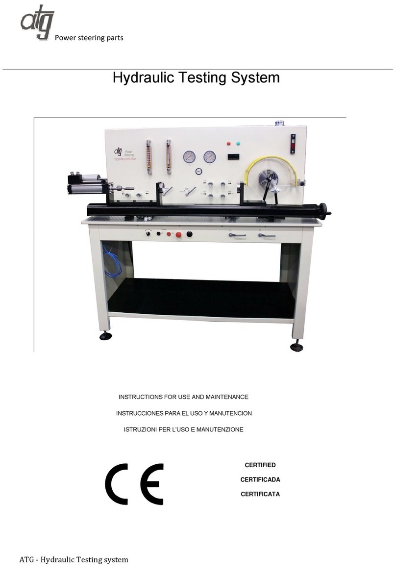
ATG EPS Specification sheet

Power steering parts
ATG - Eps Testing system
INDEX/INDEX/ INDICE/
ENGLISH
(EN)
.......................................................................................................................... 1
FRANCAIS
(ES)
......................................................................................................................2
ITALIANO
(IT)
...........................................................................................................................3

Power steering parts
ATG - Eps Testing system
INDEX
1 INTRODUCTION TO USE........................................
2 INSTALLATION ......................................................
3 INSTRUCTIONS .....................................................
1 INTRODUCTION TO USE
Before starting work with your machine, carefully read this
instructions manual so that you are familiar with the
machine and its uses and where it should not be used.
Keep this manual in a safe place. It is an integral part of
the machine and should be used for reference in operating
the machine correctly and in the proper safety conditions.
Use the machine only and exclusively for the uses
specified below, as recommended in this manual. The
machine should not in any way be tampered with, or
forced, or used for unsuitable purposes.
1.1 CONVENTIONAL SYMBOLS
Never underestimate the warnings “ATTENTION -
CAUTION” given in this manual. In order to draw the
user’s attention and to preserve safety, hazardous
operation are preceded by symbols and notes that point
out the danger and explain how to behave to avoid any
risk. These symbols and notes are divided in three
categories, identified by the following words:
WARNING: dangerous-behaviours that could
cause serious injuries.
CAUTION: behaviours that could cause slight
injuries or damages to things.
NOTE: the notes preceded by this symbols are
technical and are aimed at making operations
easier.
1.2 SAFETY AND RULES
The machine was designed and built according to the
Community Directives in force EC/2006/42 - EC/2006/95/
EC/2004/108.
Moreover, all technical standards relating to this type of
product have been complied with which provide warranty
of compliance with above mentioned directives.
The enclosed CE declaration of conformity together with
the CE brand on the product essentially comprise and are
an integral part of the machine : both guarantee product
conformity with the aforesaid safety Directives.
1.3 SAFETY PLATES/LABELS
The safety plates/labels and indicators present on the
machine, the location of which is shown in the Figure on
the inside cover, are as follows:
- Wear safety masks or goggles
- Do not insert hands in this area
with the tool operating.
Danger of dragging/cutting.
- Attention to dangerous voltage
- Read this manual
1.4 RECOMMENDED AND NOT RECOMMENDED
USAGE
This machine has been designed and developed for testing
electric power steering and EHPS.
1.5 STANDARD SAFETY PROCEDURS
• Do not use the machine in very damp places or in the
presence of inflammable liquids or gases.
• Do not use it in the open air when general weather and
environmental conditions are unfavourable (eg. explosive
atmospheres, during a storm or rain).
• Do not force the machine unnecessarily
• Wear suitable clothes, without wide sleeves or articles
such as scarves, chains and bracelets which could get
caught in the moving parts.
• Always use personal protection devices: protective
goggles as recommended by safety standards, gloves of
the right size, headphones or earplugs, and hairnets if
necessary.
• Use the tools recommended in this manual if you want
to achieve the best performance from your sawing
machine.
• Do not use the power supply cable to disconnect the plug
form the outlet. Protect it from sharp edges and do not
expose it to high temperatures.
• Any power cable extensions must be type approved abd
comply with safety standards.
• Avoid using the machine if your psycho-physical
condition are precarious or upset or under the effects of
alcohol or sedatives.
1.6 SAFETY PROCEDURS FOR FURTHER RISK
WARNING: Always keep hands away from the
working areas while the machine is moving: before
loading or unloading the part switch off the motor
working.
• Always keep clean area.
• The parts to be cut must always be held firmly using
proper bolts.
• Before carrying out any maintenance work, always
disconnect the power cable for the mains.
• Check that all safety guards are sound and positioned
correctly before starting any work.
1.7 NOISE CONDITIONS
The measurement of the noise level in compliance with
standards EN61029, EN3744 and EN11201 gave the
following results (value of 3 dB uncertain).
The surface sound pressure level Lp.
- Lp ˂ 70dB(A) during operation
The sound power level Lw.
- Lw ˂ 70dB(A) during operation
The frequency root mean RMS weighed for hand-arm

Power steering parts
ATG - Eps Testing system
acceleration does not exceed 2.5m/s².
The measurements are taken in accordance
with standards UNI7712, ISO3740, ISO 3746 and
EC/2006/42.
The emission levels indicated are not necessarily safety
levels. Although there is a relationship between the
emissions and exposure levels, the values shown cannot
be used for establishing the need for further precautions.
There are other factors which influence the exposure
levels of operators, such as the features of the work place,
presence of other sources of noise, number of machines
running, etc.
The exposure levels may also vary between countries.
This information is necessary for the user for better
evaluation of the risks and hazards deriving from noise.
1.8 INFORMATION ABOUT ELECTROMAGNETIC
COMPATIBILITY
The european regulations on safety and in particular
the EEC directive 2004/108 contemplate that all the
equipment be equipped with shielding devices against
radio interferences both from and towards the outside.
This machine is equipped with filters both on the motor
and on the power supply through which the machine is
safe and in compliance with above regulations.
Tests were carried out according to 61000-6-1, EN
61000-6-3, EN 55014-1, EN 55014-2 regulations.
1.9 DESCRIPTION OF THE MACHINE (Fig. 1)
The machine consists of a machine body D complete with
brake F and gear.
In the base N there are: EPS plate for B, and a plate for
electric rack C and a rack E.
The EPS and electric rack are fixed with the tool L. The
electrical connections are made with cables I, diagnosis by
means of the cable 6.
There are also a power supply G, a computer H, a monitor
A, a battery N.
A Monitor
B Eps plate
CElectric rack plate
D Machine body
E Rack
F Brake
G Power supply
H Computer
I Cables
L Tool
M Cable 6
N Battery
VERSIONE EPS
WEIGHT: ............................................................... 500 Kg.
SIZE:.............................................cm 1000x1500 x H 1800
PACKAGING SIZE: .....................cm 1770X1240 x H 1760
2 INSTALLATION
2.1 REMOVING THE PACKING
The machine is delivered inside a box suitable for the
purpose.
Therefore, the packing must be removed completely by
means of suitable tools and care must be take in order to
avoid damage to any part of the machine.
For packing disposal, please refer to 6.4 point.
2.2 HANDLING AND TRANSPORTION (Fig. 2)
The machine and must be moved only using suitable lifting
devices.
WARNING: Do not try to move or lift the
machine by hand even if more people are
present.
WARNING: The operations described in this
manual relative to sling, transport and lifting
by means of a fork lift or hoist must be carried
out only by skilled and qualified personnel
(EC/2006/42).
Move the machine carefully and avoid sudden movements
which could unbalance the load and make it drop.
To remove themachine from the plate after packing removal,
loosen the fixing screws but keep them should the machine
be transported for long stretches.
To move the machine while it is still inside the packing, use
a fork lift by inserting the two forks in the rooms provided
under the hearing board.
2.3 ELECTRICAL CONNECTIONS
Check that the mains to which the machine is connected is
earthed in accordance with current safety regulations and
that the power point is in good condition.
Connect a plug in compliance with safety rules to the
end of the mains cable of the machine, checking that the
yellow/green protective conductor is fitted into the relative
terminal marked.
Remember that there should be a magnetothermic
protective device fitted upstream of the mains to protect all
the conductors from short circuits and overloads.
This protective device should be selected according to the
electrical features of the machine stated on the motor.
The motor of your machine is equipped with a protective
heat circuit breaker which interrupts the power supply
when the temperature of the coils rises too high.
When the power supply is interrupted, wait for normal
reset.
UNIVERSAL VERSION (Fig. 4)
In case of power failure in mains, while you wait for power
to be restored there is no danger hazard may arise : in
fact, the electronic speed variator is also equipped with a
reset function which prevents the machine from re-starting
automatically. To start the machine, press the start push
button A on the handgrip twice.
WARNING: Never change setting to avoid
overloads which could damage the electric
circuits and other mechanical members.
Your machine is equipped with a motor protection
obtained through a amperometric limiter which prevents
the motor from absorbing a current higher than the set
one, expressed by the maximum prescribed value of
absorption.
2.4 POSITION/WORK STATION (Fig. 2)
Position the machine by moving it as described in
paragraph 2.2
Taking the ergonomic criteria into consideration, the ideal

Power steering parts
ATG - Eps Testing system
height shall be that which enables you to position the
table between 90 and 95 centimetres from the floor (see
Fig. 2).
CAUTION: Make sure that the machine is placed
in a working area with suitable
environmental conditions and lighting.
The general conditions of the working
environment are of fundamental
importance for accident prevention.
3 INSTRUCTIONS
3.1 DISPOSAL OF THE MACHINE AND
PACKAGING
INFORMATION FOR USERS
In accordance with art. 13 of Legislative
Decree
25th July 2005, no. 151 “Implementation
of
Directives 2002/95/EEC, 2002/96/EEC and 2003/108/
EEC, relative to reducing the use of hazardous
substances
in electrical and electronic appliances and the disposal of
waste”, please take note of the following:
• The crossed out wheelie bin symbol found on the
appliance or on the packaging, indicates that the product
must be disposed of separately from ordinary household
waste when it reaches the end of its working life.
• The user must consign the unwanted appliance to
an authorized differentiated waste disposal centre for
electrical and electronic goods, or alternatively, hand
it over to the relative dealer on purchasing a new
appliance of the same type on the basis of a one to
one ratio.
• Differentiated disposal, to enable possible recycling
or environmentally compatible elimination of the
appliance, helps to limit undesirable effects on health
and the environment and promotes the reuse and/or
recycling of the materials which went into making up
the appliance.
WARNING: Sanctions, in accordance with
the relative legislation in force in the
country of use, will be imposed on the user
if the appliance is disposed.

Power steering parts
ATG - Eps Testing system
Select in the upper menu -->Fiat-->Punto 188 ECU 1075
This is the main page that will be showed
Click the 'ON' button in the 'Power supply' box. The green light comes on, the main relay is engaged and the reading of brake and
chuck position will start itself.

Power steering parts
ATG - Eps Testing system
The testing bench verify if the DC voltage is inside the range from 12Volt to 15 Volt, if it is out of range the following two message will
appear (Low voltage or Over voltage):
The DC voltage is set by means of DC power supply unit and a 100Ah Battery. You can adjust the voltage acting on the potentiometer
located in the power supply unit. We suggest to set it between 13Volt and 13.5 Volt.
When you click over 'ON' button in the 'Ignition key' box the bench start the dialog with EPS ECU.
It checks first if there are errors so relevant to switch the red light in the car and this condition is showed in the 'Error' box. There can be
a red light or green light.
At the same time the reading of the total list of errors is showed in the 'Calibration' box.
In this box you can find a button that is used to delete the errors in the ECU. If the error after clicking over 'Delete' are showed again
means that they are actual error and they are
ACTIVE in this moment. All the errors are deleted but the ACTIVE errors comes back and are showed again.

Power steering parts
ATG - Eps Testing system
In the 'Receive' box you can see that the dialog is running.
If there are errors inside the ECU of the EPS they will be showed in the 'Calibration' window.
You can decide to use an external diagnostic tester (for example Texa, Bosh, Brain Bee), in this case you have to click over
'Internal/External diagnose'.
'Calibration' box will be disabled and the external tester will be enabled.

Power steering parts
ATG - Eps Testing system
If you decide to use an external diagnostic tester you have to plug it to the interface set inside the bench, near to the computer.
In the specific case of Punto 188 ECU 1075 you have to use 'Cable #6'
Using 'EPS testing system' you can apply a load to the Eps under test by means of an electromagnetic brake. You can activate it
clicking over 'ON' button in the 'Brake' box.
You can see the braking torque during the test, select different speed and test the EPS accordingly.

Power steering parts
ATG - Eps Testing system
Volkswagen GOLF V
Following you can find instruction for testing EPS of Golf V.
Assembly together the tool #1 (main plate) and the 2 pieces of tools #3 (vertical support for GolfV). Fit the EPS on the support locking
it with M8 bolt.
Put the chuck in the middle position and put in the middle also the Main Rack under the yellow guard.

Power steering parts
ATG - Eps Testing system
Select in the upper menu -->Volkswagen-->Golf V
This is the main page that will be showed.
Click the 'ON' button in the 'Power supply' box. The green light comes on, the main relay is engaged and the reading of brake and
chuck position will start itself.

Power steering parts
ATG - Eps Testing system
The testing bench verify if the DC voltage is inside the range from 12Volt to 15 Volt, if it is out of range the following two message will
appear (Low voltage or Over voltage):
The actual DC voltage is showed in the 'Power Supply' box.
The DC voltage is set by means of DC power supply unit and a 100Ah Battery. You can adjust the voltage acting on the potentiometer
located in the power supply unit. We suggest to set it between 13Volt and 13.5 Volt.

Power steering parts
ATG - Eps Testing system
When you click over 'ON' button in the 'Ignition key' box the bench start the dialog with EPS ECU.
It checks first if there are errors so relevant to switch the red light in the car and this condition is showed in the 'Error' box. There can be
a red light or green light.
At the same time the reading of the total list of errors is showed in the 'Calibration' box.
In this box you can find a button that is used to delete the errors in the ECU. If the error after clicking over 'Delete' are showed again
means that they are actual error and they are ACTIVE in this moment. All the errors are deleted but the ACTIVE errors comes back and
are showed again.
In the 'Receive' box you can see that the dialog is running and in the right box you can see the step procedure of reading errors.
In this window you can check the ABSOLUTE torque that is applied to the wheel, The current that is absorbed, and if there are relevant
active errors.
Table of contents
Languages:
Other ATG Test Equipment manuals