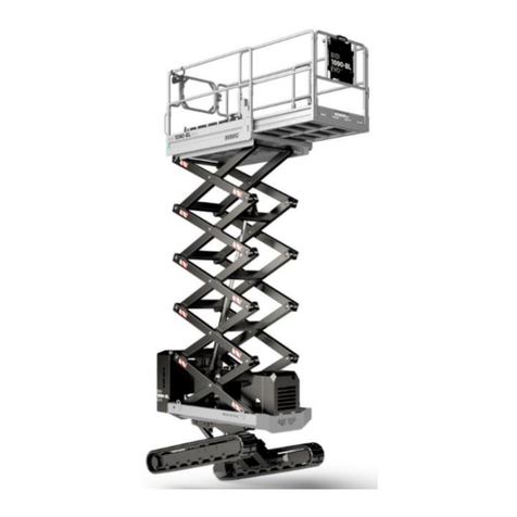
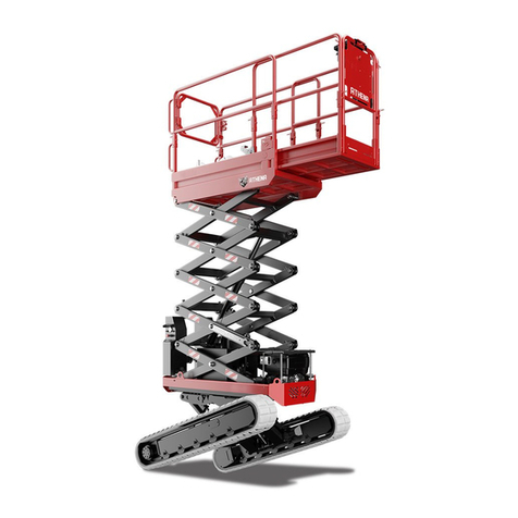
Athena 1470-HE EVO Setup guide

ATHENA1470-HEEVO
Translationoforiginalinstructions
Prior to commissioning the machine read carefully this Use and
Maintenance Manual
Note: table of contents at the end of the manual
Edition
Date
00
04/07/2017

PAGE 2
1GENERAL INFORMATION
1.1 Documents supplied with each machine
•CE Declaration of conformity
•Instruction Manual (this manual)
•Spare Parts Manual
•Wiring diagrams and hydraulic layouts
•Report register
1.2 Details of Manual
•Instruction manual for Elevating work platform
•Model Athena 1470-HE EVO
Note: Some of the photos and illustrations may not refer specifically to the
version of the machine in your possession, but provide indications concerning
the purpose for which they have been included.
RECIPIENTS OF THIS MANUAL
•User
•Maintenance technician
Warning: the servicing personnel must be properly trained and experienced.
CAREFULLY READ this manual before performing any operation on the machine.
If in doubt, do not improvise. Call the assistance service.

PAGE 3
1.3 Ownership of the information
This document contains confidential information. All rights reserved.
This manual may be neither partially nor totally duplicated without the prior
written authorization of ALMAC s.r.l.
This document may only be used by the customer to whom the manual has been
supplied along with the machine, and only for the purpose of use and
maintenance of the machine to which the manual refers.
ALMAC s.r.l. hereby declares that the information in this manual was congruent
with the technical and safety specifications of the machine to which the manual
refers. The manufacturer declines all liability for direct or indirect damage to
persons, things or animals deriving from use of the machine in conditions
differing from those envisaged.
ALMAC s.r.l. reserves the right to make changes or improvements, without prior
notice, to the documentary material and to the machines, including marketed
machines of the same model as that to which this manual refers but with a
different serial number.
The information contained in this manual refers in particular to the machines
specified in "Identification data of the M.E.W.P." and related documentation.
1.4 Manufacturer's identification data

PAGE 4
1.5 MEWP identification data
The machine named Athena 1470-HE EVO is defined according to technical
standards in force (ref. EN UNI EN 280:2015), as:
Mobile Elevating Work Platform (MEWP), belonging to group A, type 3 (point
1.4-EN 280)
Meanings:
GROUP A: Mobile elevating work platforms where the vertical projection of the
centre of the platform area in all platform configurations at the
maximum chassis inclination specified by the manufacturer is
always inside the tipping lines.
TYPE 3: mobile elevating work platforms where travelling with a raised
work platform is controlled from a point of control on the work
platform.

PAGE 5
ASPAC GROUP
ELEVATING WORK PLATFORM
MANUFACTURER ALMAC s.r.l.
CAUTION. THIS PLATFORM IS NOT VOLTAGE INSULATED
YEAR OF
MANUFACTURE
DATE OF TEST
RATED LOAD INC. 2 OCCUPANT & TOOLS
MAX ALLOWABLE SIDE FORCE
MAX WIND SPEED
MAX PLATFORM HEIGHT
MAX WORKING HEIGHT
MAX HORIZONTAL WORKING OUTREACH
MAX UPPER GRADIENT IN RUNNING DIRECTION
COUNTRY OF MANUFACTURE
HYDRAULIC PRESSURE (TRAVEL)
HYDRAULIC PRESSURE (ELEVATING)
BATTERY VOLTAGE
MAX ALLOWABLE INCLINATION OF CHASSIS
THIS MACHINE COMPLIES WITH
STATE DESIGN REGISTRATION NUMBERS
NSW: VIC: SA: QLD:
Designed and Manufactured by: Distributed by:
Almac s.r.l. ASPAC GROUP
Via Ruggeri 6/A 3/84 Hallam South Road
42016 Guastalla (RE) Hallam Vic 3803
Italy Australia
12,5 m/s
ITALY
190 bar
1,01 mt
150 bar
12 V
1°
AS 1418.10.2011
250 kg
5,99 mt
7,99 mt
25° (47%)
40 daN
UNLADEN WEIGHT
WITH TRACKS
MODEL SERIAL
NUMBER
Kg
Identification plate
Refer to the data on the identification plate for an exact identification of the
MEWP.
MEWP
ALM-000631
2018

PAGE 6
1.6 Performance
Below are the configurations that the mobile elevating work platform can have
during operation and transport.

PAGE 7

PAGE 8
Characteristic dimensions
Chassis length
A1
m
2,16
Machine length
With stabilisers open
A2
mt
3,18
Length of retracted work platform
A3
mt
2,62
Machine width
With stabilisers open
A4
mt
1,53
Width of crawler
A5
mm
250
Min height of floor surface
A6
mt
1,69
Minimum height
A7
mt
2,80
Width of work platform
A8
mt
1,14
Chassis width
A9
mt
1,15
Machine length
With stabilisers in line
A10
mt
3,35
Minimum height (transport only)
Railings closed
A11
mt
2.15
Length of extended work platform
A12
mt
4,00
Dismantle the railings only for special transport situations; before
commissioning, the machine must be reconfigured by skilled and
authorised personnel, according to the certified diagram, following the
manufacturer's instructions

PAGE 9
Work area on stabilisers in wide position.
Maximum inclination allowed: ± 0.5°
B9
B10B8
B12
B11
B4
B6 B7
B3
B5 B5
B2
B1

PAGE 10
Characteristic dimensions
Maximum work height
B1
mt
14,22
Min height of floor surface
B2
mt
12,22
Maximum work space in width
B3
mt
2,08
Maximum work space in length
B4
mt
5,02
Useful work distance in width
B5
mm
280
Useful work distance in length
B6
mm
140
Useful work distance in length
B7
mt
1,70
Distance between the stabilisers in width
B8
mt
1,4
Maximum height of track from ground
B9
mm
470
Distance between the stabilisers in length
B10
mt
2,83
Extension of work platform
B11
mt
1,37
Length of extended work platform
B12
mt
4,00

PAGE 11
Work area on stabilisers in narrow position.
Maximum inclination allowed: ± 0.5°
7160
9160
1000
1130
3230
3480
11°
10°
24°
2080 5020
4000 1370
10 1680
460
460
Warning! It is sufficient to position a single stabiliser in the narrow position to
have the work area on stabilisers in the narrow position.

PAGE 12
Work area on tracks.
Travel not allowed
Maximum inclination allowed: ± 2°
5020
5490
7500

PAGE 13
Work area on tracks.
Travel allowed at reduced speed.
Maximum inclination allowed: ± 2°
5020
4560
6560
Technical data
Capacity of work platform
kg
300
Number of operators on work platform
2
Lifting time (with 300Kg on the platform)
s
60
Lowering time
s
60
Hydraulic side-shift pressure
Bar
195 ± 5
Hydraulic lifting pressure
Bar
195 ± 5
Climb angle
°
25
Maximum side slope of the terrain
°
15
Maximum longitudinal slope of the terrain
°
25
Oil tank capacity
l
60
Maximum speed with platform lifted
km/h
0.4

PAGE 14
Technical data
Maximum travelling speed
km/h
2.2
Overall weight
kg
3480
Max wind force
m/s
12.5
Starter battery voltage and capacity
V/Ah
12/50
Weight of starter battery
kg
15
Sound power LwA
dBA
104
Sound level at operator position Lp (indoor industrial
environment)
dBA
84.5 ± 2.6
Sound level at operator position Lp (outdoor environment on
asphalt)
dBA
79.5 ± 2.6
Max peak level Lppeak
dBC
106.0
Vibrations transmitted to hand/arm system (operator hand
rest)
m/s2
< 2.5
Whole-body vibration (platform-measured on flat ground)
m/s2
0.52 ± 0.10 *
Vibrations transmitted to hand/arm system (operator hand
rest)
m/s2
0.59 ± 0.12 **
Max Manual Force
daN
40
* values refer to platform raised (operating height)
*** values refer to platform at the transport height limit
Standard equipment
Optional equipment
Electrohydraulic controls
Electrical engine 230 V / 50 Hz
Internal combustion engine (KUBOTA
Z602)
Sine wave inverter 1000W
Automatic accelerator
Cable remote control
CANBUS display to manage working
hours and alarms
Dual speed gear motors
Warning buzzer
Anchorage points for lifting-lowering
Harness anchorage points
Electric starter on work platform
Overload control

PAGE 15
Electronic tilt control
Electronic anti-shearing protection
Engine specifications
Z602-E3B TIER 4
Dry weight
60 kg
Type of engine
4 TIMES – LIQUID COOLING - DIESEL
Swept volume
599 cm3
Net power
12.5 kW @ 3600 rpm
Net torque
38 Nm @ 2500 rpm
Q.ty engine oil
3 Lt
Fuel tank capacity
30 Lt
Engine specifications
Electrical
Dry weight
14 kg
Installed power
2.2 kW
Torque
10.2 Nm
Rpm
1400
Power supply
230 V / 50 Hz
IEC Size
90

PAGE 16
1.7 CE Declaration of Conformity
See facsimile of CE declaration of conformity enclosed with this manual.
The machine described in this manual complies with the following standards:
•Directive 2006/42/EC – Machinery Directive that amends Directive
95/16/EC
•Legislative Decree D.Lgs 17/2010 – Implementation of Machinery Directive
2006/42/EC
•UNI EN 280:2015 - Mobile elevating work platforms - Design calculations -
Stability criteria - Construction - Safety - Examinations and tests
•*UNI EN 349:2008 – Minimum gaps to avoid crushing parts of the human
body
•EN ISO 12100:2010 Safety of machinery -General principles for design -
Risk assessment and reduction
All parts available on the market and “partly completed machinery” installed on
the platform conform to the aforementioned Directives and those that
specifically govern the product.
*For the scissor lifting devices, the anti-shearing function has been used, as
provided for in Point 5.4.3 of UNI EN 280:2015 with permanent warning signs.
1.8 Warranty
ALMAC S.r.l. guarantees the equipment it manufactures and undertakes to
replace, free of charge and within the shortest possible time, those parts that,
in its opinion, possess manufacturing and/or material defects.
Work under guarantee must only be performed by workshops authorized by
ALMAC S.r.l. and only when the Customer is up to date with the payments.
The Customer will not be entitled to work under guarantee unless he consigns
the equipment for repair within 30 days from the date of the first complaint, to
be made in writing.
With the exception of fraud or gross negligence, ALMAC S.r.l. is relieved of all
liability towards the Customer for damage deriving from flaws/defects in the
traded equipment.
The warranty with which the Customer is provided becomes void if modifications
are made to the machines without prior written authorization from ALMAC S.r.l.
or should the Customer make incorrect/improper use of the machines.

PAGE 17
1.8.1 Request for interventions during warranty period and formalities
ALMAC S.r.l. must be notified of requests for spare parts or technical
interventions under guarantee as soon as a defect is discovered.
Always indicate the type of machine and its serial number when requesting
spare parts under guarantee or technical interventions under guarantee. This
information is given on the identification plate of the equipment.
1.9 Assistance
As far as the optimum use of the machine and extraordinary maintenance are
concerned, this manual does not replace the expertise of the Technical
Assistance sent by ALMAC S.r.l. (refer also to the Maintenance Chapter).
1.9.1 Request for assistance and repairs
To request ALMAC S.r.l. specialized Assistance Service, the Customer may
contact:
In case of intervention request, specify the machine version and serial number;
the data is indicated on the identification plate attached to the machine.

PAGE 18
1.10 Use of the manual
Note: Keep this manual in an accessible place known to all users (operators and
maintenance workers).
Note: This manual must be kept in a protected place inside the compartment
provided on the work platform so that it can be easily accessed for consultation
throughout the entire technical life of the machine.
Note: If this manual is lost or damaged, a new copy must be ordered from the
manufacturer. Specify the serial number of the machine (given on the relative
identification plate) when requesting a new copy of the manual. The
manufacturer undertakes to provide a new copy.
Note: When selling used equipment, this manual and the related attachments
must be included and the manufacturer must be informed of the new owner (see
Appendix 3 - Transfer of Ownership)
Read carefully Chapter 1 General Information, Chapter 2 Safety information,
Chapter 3 Description of the Machine and Performance, Chapter 4 Operating
instructions, Chapter 5 Emergency Procedures.
Always consult the relative chapter when using, servicing the machine or when
it is demolished.

PAGE 19
1.11 Intended use and improper uses
1.11.1 Intended use
The machine described in this manual is a self-propelled elevating work platform
designed to lift personnel and equipment to perform the following jobs:
•professional gardening and general work
•installation of systems and equipment
•cleaning
•painting and paint removal
The maximum allowed capacity for this model is 300 kg. Consider the following:
•2 (two) persons each weighing 80 kg
•140 kg of equipment
An electronic control system prevents the work platform from lifting to any
position when the load exceeds approx. 20% of the rated load given in the
technical specifications.
The platform was designed and built to be driven only from the console located
on the work platform.
The push-button is of the removable type and can only be used by the operator
to control the platform exclusively in transport position.
The controls on the ground on the rear side are for EMERGENCY use or
MAINTENANCE by qualified personnel.

PAGE 20
Attention: NEVER exceed the machine's established maximum capacity.
Attention: It is FORBIDDEN to transport large slabs or materials since this could
increase wind resistance to a considerable extent and cause the machine to tip
over.
Attention: It is FORBIDDEN to apply horizontal loads to the platform when the
machine is moving (e.g. the operators on board must not pull ropes or cables…)
Attention: It is FORBIDDEN to use the machine to tow other equipment or
vehicles.
Warning: the machine is designed to be driven around within public or private
areas. It is not designed for road circulation
Warning: The machine IS NOT SET FOR OPERATION IN ATEX CLASSIFIED
ATMOSPHERES
ALL LOADS must be positioned inside the work platform. NEVER LIFT LOADS
HANGING FROM THE PLATFORM, from the lifting structure or from the railings.
If the machine is used in places open to the public or in construction sites where
persons may transit or remain in the vicinity, the WORK AREA MUST BE
CORDONED OFF in a suitable way (e.g. chains and posts).
Table of contents
Other Athena Lifting System manuals
Popular Lifting System manuals by other brands

Bend-Pak
Bend-Pak RBJ4500 Installation and operation manual

Bend-Pak
Bend-Pak HD-12LS Installation and operation manual

Bend-Pak
Bend-Pak HDS-18E Installation and operation manual

Bend-Pak
Bend-Pak XPR-10AS Service manual

Bend-Pak
Bend-Pak HDS-40 Service manual

ARJO HUNTLEIGH
ARJO HUNTLEIGH Malibu Sovereign Maintenance and Repair Manual