Athena GET ECULMB RACE KIT User manual

1
V.2
IT
EN
ES
FR
DE
PT
INSTALLATION GUIDE FOR:
GUIDA PER L’INSTALLAZIONE SU:
GUÍA DE INSTALACIÓN PARA:
GUIDE D’INSTALLATION POUR:
INSTALLATIONSANLEITUNGEN FÜR:
GUIA DE INSTALAÇÃO PARA:
GAS GAS
EC 250 2021-2023
EC 300 2021-2023
HUSQVARNA
TE 250i 2018-2023
TE 300i 2018-2023
KTM
EXC 250 TPI 2018-2023
EXC 300 TPI 2018-2023
EFI 2T ECU + INJECTORS SUPPORT KIT
ECULMB RACE KIT

2
ENGLISH
EN
A. WARNINGS FOR CORRECT USE
Read all the instructions and warnings carefully before
using GET Eculmb Race Kit. Failure to read and/or observe
the instructions and warnings can lead to incorrect use of
the device or its malfunction, resulting in product damage
and personal injuries.
GET ECULMB RACE KIT IS INTENDED ONLY AND
EXCLUSIVELY FOR RACING USE.
GENERAL WARNINGS
1. Follow the instructions described in this manual to prevent
vehicle damages.
2. Do not modify or replace the material supplied by GET.
3. Always make sure that no installed part can interfere with
the hot parts of the engine, the steering components or with
the rider.
4. The product is not a toy. Keep it out of the reach of children
and/or animals as it contains small sized components that
could be swallowed.
5. Do not use the product for purposes other than those
specified in these instructions.
6. Do not use high pressure washers on the product.
SPECIFIC WARNINGS
1. Always make sure that GET ECULMB is properly installed
and functional prior to use.
2. Never expose the device to temperatures above
70°C/158°F.
3. Install it when the engine is cold.

3EN
4. When GET ECULMB is installed, if an OEM air filter and/or
and OEM exhaust system are not installed on the bike, this
could lead the engine to lose power. To fully exploit engine
performance, use only original air filter and exhaust system.
5. To use and manage the GPA technology, it is necessary
to install GET GPA Switch or GET LC-GPA module (both sold
separately) or manage it with GET Maya Software (sold
separately).
6. To change GET ECULMB injection map, it is necessary to use
GET Maya programming software (sold separately).
7. If the bike does not start or the engine is irregular, be sure
that the version of GET ECULMB chosen is compatible with
your bike model and year. Verify that ECULMB is properly
connected and perform a TPS calibration (see section F.
TUNING - ZERO TPS CALIBRATION).
8. Do not remove the thermostatic valve: removing it may
cause damage and/or malfunction.
9. Keep the exhaust control OEM setting measurement to
avoid engine malfunctions:
300cc engines: 2,3 mm (0.091“)
250cc engines: 2,7 mm (0.106“)
10. Use only OEM spark plugs to avoid engine malfunctions.
Check the proper spark plug model on your vehicle manual.
11. Periodically check the engine compression ratio (see your
motorcycle manual) to avoid malfunctions and to fully exploit
GET performance kit.

4EN
B. PRODUCT LAYOUT
MAP SWITCH + EXPANSION CABLEWiFi-COM
AUX
GET ECULMB
Hose clamps (6x)
GET Fuel hose
Intake flange gasket
M6x30 mm screws (4x)
Injector caps (2x)
M5x25 mm screws (4x)
Injector support spacers (4x)
M4x12 mm screws (4x)
Injector support
Injector support brackets (2x)

5EN
MAIN GET ECULMB FEATURES:
• Get the best performance out of your engine
GET ECULMB kit is a racing kit developed to take the most out
of the engine without compromising the reliability. It ensures an
impressive power increase and an improved rideability.
• Two preinstalled racing maps
GET ECULMB unit is ready with two reprogrammable maps:
- Map 1: Racing configuration for full power
- Map 2: Balanced configuration for a smooth power delivery
• Engineered and tested in GET laboratories
The kit and the maps are designed for your specific machine. It is
developed by GET technicians involved daily into R&D studies on
racing bikes and strict quality tests on dyno and on track.
RACE KIT ECULMB includes a programmable plug&play control
unit and a specifically developed aluminum injector support.
The support allows to move the injectors from the cylinder,
placing them between the cylinder and the throttle body to
allow a massive power increase and a smoother rideability.
It is possible to adjust the calibration maps through both WiGET
App, by using the WiFi-COM device, and/or MAYA software.
WiGET App
The ECULMB unit comes with 2 maps developed by GET R&D
Department, which can be easily switched thanks to the Map
Switch included in the kit.

6EN
C. PREPARATORY STEPS
KEEP THE ENGINE TURNED OFF AND REMEMBER TO
WORK UNDER SAFETY CONDITIONS.
1. Remove the seat and find the OEM battery, which is normally
placed under the seat. If needed, check on your motorbike’s
workshop manual where to find it.
2. Disconnect the positive battery pole.
3. Remove the OEM EFI pressing the retainer clip of the loom
connector before pulling it: make sure to unplug the connector
without damaging it.
4. Unplug the fuel pump connector and the fuel line pump plug
from the fuel tank. Remove the fuel tank and the exhaust system
to lift the rear subframe. Remove the upper engine mount
brackets to have free access to the OEM injectors. Check on your
motorbike’s workshop manual where to find these components.
5. Remove the throttle valve body, which is normally placed on the
left side of the bike, between the intake manifold and the airbox.
Check on your motorbike’s workshop manual where to find these
components.
6. Unplug the injectors’ harness and the injectors from the
cylinder. Remove the fuel distributor from the bike.
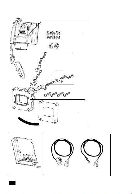
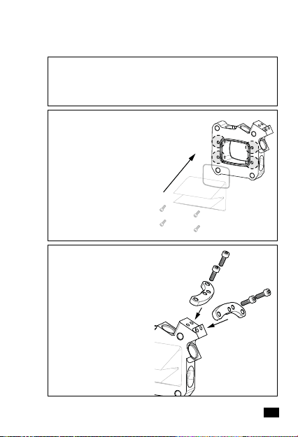
7. Install the two injector caps provided in the kit on the injector
holes on the cylinder and tighten the screws.
8. Unscrew the intake flange and remove the reed valve. The
intake flange gasket, included in the kit, and the OEM intake
flange screws will not be used. Disassemble the OE reed valve
supporting plate, which will not be used to complete GET
ECULMB Race kit installation. Remove the four OEM reed valve
screws and the o-ring from the supporting plate.

7EN
D. INJECTOR SUPPORT INSTALLATION
1. Install the o-ring removed in the previous step on GET
injector support.
2. Install the OEM reed
valve on GET injector
support and fix it with
the four OEM reed
valve screws previously
removed.
3. Install the two
red injector support
brackets on GET injector
support using the four
M4x12 mm screws.
INJECTOR SUPPORT AND FUEL DISTRIBUTOR ASSEMBLY

8EN
4. Remove the injectors
from the fuel distributor
and place them on GET
injector support. Place
the spacers provided
in the kit between the
red brackets and the
OEM injector brackets.
Fix the OEM injector
brackets together with
the spacers and the red
injector support brackets
using the four M5x25mm
screws provided in the kit.
5. Disassemble the previously removed fuel distributor
in 7 parts: 3-way fitting, supply hose, 2 injector fuel hoses,
2 injectors, fuel line pump plug.
6. Using the OEM 3-way fitting assemble a new fuel
distributor. Remove the OEM right injector fuel hose (“B”,
the longest hose) and replace it with the OEM supply hose
“C”. The OE right injector fuel hose “B” will not be used. Install
GET fuel hose as the new supply hose, while the left injector
fuel hose “A” remains in the same position. Insert the fuel line
pump plug into the left injector fuel hose “A”. Insert the right
OEM injector into GET fuel hose, insert the left OEM injector
into “C” fuel hose. Fix all the connections using hose clamps.
A B
RL
C
C
GET
hose
L
A

9EN
7. Connect the injector fuel hoses to the injectors. Use
hose clamps to fix them.
8. Fix GET injector
support and the OEM
intake flange with the
four M6x30 mm provided
screws. Assemble them
to the engine case
placing the intake flange
gasket, included in the
kit, between them.
To engine
case
4x
9. Re-install the injectors’ harness, the throttle valve
body, the upper engine mount brackets. Put the rear
subframe back in the original position. Plug the fuel line
pump plug and the fuel pump connector to the fuel tank.
Fix the fuel tank and install the exhaust system.

10EN
1. Before installing GET
ECULMB unit use a zip
tie to keep it firm while
riding: pass the zip tie
under the OEM harness.
Connect GET ECULMB
unit to the OEM loom
connector and tighten
the tie bundling together
GET ECULMB connector
with the harness below.
AUX
2. Install other GET accessories, e.g. GET Map Switch
and GET WiFi-COM (see section E. ACCESSORIES
INSTALLATION).
3. Re-install the seat. Pay attention that GET ECULMB,
once the seat is installed, is well positioned and does not
collide with the seat.
GET ECULMB INSTALLATION

11 EN
MAP SWITCH INSTALLATION
1. Install GET Map
Switch to the handlebar.
2. Connect MAP Switch
faston terminals to the
MAP Switch expansion
cable faston terminals.
3. Connect the
expansion cable to the
“AUX” connector of the
ECULMB unit.
ECULMB
AUX
EXPANSION
CABLE
ATTENTION: After the installation, check that the wiring
does not obstruct the free movement of the handlebar in
both directions or interfere with the moving components
of the motorcycle (e.g., transmission) or with the rider
(e.g. the boot area).
REMEMBER TO WORK UNDER SAFETY CONDITIONS
AND TO KEEP THE ENGINE TURNED OFF.
E. ACCESSORIES INSTALLATION
WIFI-COM INSTALLATION
Install the WiFi-COM by following the dedicated manual.

12EN
F. TUNING
IDLE REGULATION
For the best idle speed, it is necessary to perform the idle
regulation. This operation influences the vehicle starting
behavior, a stable idle speed and the vehicle’s response when
the throttle is opened. The engine may go out spontaneously if
the idle speed is set too low. An incorrect idle speed can have a
negative impact on overall engine running.
ATTENTION: For M.Y. 2018-2019, KTM and
HUSQVARNA updated both OEM EFI calibration and
idle screw regulation. See section F. TUNING - ZERO
TPS CALIBRATION – with GET WiFi-COM, to verify if
it is necessary to update your GET ECULMB firmware
and to modify the idle screw setting.
ATTENTION: Remember to remove the Wake-up
connector after the use to avoid discharging the battery.
ATTENTION: Maps are editable only with GET
ECULMB firmware MB2TPI07 or newer versions (e.g.,
MB2TPI08, MB2TPI09). Check the ECULMB firmware
with GET WiFi-COM provided in the kit. Open the
menu in WiGET app, select “SYSTEM INFO” and check
the value “Fw Code”, which is the firmware code of the
connected GET ECULMB.
It is possible to use GET WiFi-COM both with the engine on or
with the engine switched off. In the latter case, it is mandatory
to use the Wake-up connector, which is included as part of the
motorcycle’s separate enclosure. Remove the protection cap
from the motorbike’s diagnostic connector and connect the
Wake-up connector. The OEM diagnostic connector can be
found near the motorcycle battery: check on the workshop
manual where to find it.

13 EN
ATTENTION: Before starting the idle regulation
procedure, make sure the emergency OFF switch is
in run position and the throttle is completely closed.
Make the setting in small steps.
1. Find the idle screw on the throttle valve body on the left
side of the bike, between the airbox and the intake manifold.
Otherwise, check on your motorbike’s workshop manual
where to find it.
2. Turn the idle screw clockwise to decrease the idle
speed and to start the tuning.
Turn it counterclockwise to increase the idle speed:
• For MY 2018/2019 bikes, rotate the screw
counterclockwise for 2,5 turns.
• For MY 2020/2023 bikes, rotate the screw
counterclockwise for 4,5 turns.
3. If you encounter any engine irregularities after a
correct idle regulation, GET suggests performing the
ZERO TPS Calibration (see following section).
ZERO TPS CALIBRATION
Zero TPS Calibration allows GET ECULMB to properly recognize
when the throttle is completely closed, and to ensure accurate
readings of the fuel level injected into the combustion
chamber. When installing a new ECU or other accessories,
GET recommends carrying out the Zero TPS Calibration. This
calibration will ensure a correct fuel calculation, so the motorbike
can accelerate accurately, and it will avoid poor fuel economy.

14EN
ZERO TPS CALIBRATION – without GET WiFi-COM
1. Twist the throttle completely forward to make sure it is in
closed position during this operation. Set the emergency OFF
switch in “run” position.
2. Remove the protection cap from the motorbike’s diagnostic
connector and connect the Wake-up connector (included
as part of the OE motorcycle’s separate enclosure). The OE
diagnostic connector can be found near the motorcycle battery:
check on the workshop manual where to find it.
3. Press and hold the switch off button for 10 seconds. By doing
this operation, the minimum TPS value is saved.
4. Remove the “Wake-up connector” to avoid discharging the
bike battery.
ZERO TPS CALIBRATION – with GET WiFi-COM
It is possible to carry out the ZERO TPS Calibration with or
without GET WiFi-COM (included in the kit).
ATTENTION: The minimum value is saved if similar
to the OE one, otherwise GET ECULMB will discard
the value because it will read it as incorrect. It is not
possible to manage the maximum value.
ATTENTION: REMEMBER TO WORK UNDER SAFETY
CONDITIONS AND TO KEEP THE ENGINE TURNED OFF.
To set Zero TPS, open WiGET
app and select “MONITOR”
section. Follow the instruction
in GET WiFi-COM manual,
included in the kit, and look at
WiGET video tutorial (minute
5:55). Scan the QR code.

15
To verify if it is necessary to update your ECULMB firmware or if
you need to modify the idle screw setting, check GET ECULMB
firmware with GET WiFi-COM provided in the kit. Open the menu
in WiGET app, select “SYSTEM INFO” and check the value “Fw
Code”, which is the firmware code of the connected GET ECULMB.
Perform the firmware update and/or the idle screw setting
accordingly to the scheme below:
IMPORTANT WARNING:
After KTM & HUSQVARNA updates on OEM EFI
calibration and idle screw setting, GET released a new
firmware (FW) and map for the new configurations.
You can always find the updated maps and firmware
on athena.eu. To install the firmware update, it is
necessary to use GET Maya Software.
EN
If the engine doesn’t start after the TPS calibration:
1. Uninstall GET ECULMB.
2. Install the OEM EFI back and resume the factory engine idle.
3. Uninstall again the OEM EFI and re-install GET ECULMB.
4. Repeat step 1, 2, 3 of “Idle regulation” and step 1, 2, 3, 4 of
“Zero TPS Calibration – without GET WiFi-COM”.
Not necessary
Necessary
Update
FW
Idle screw
setting
MY 2018 FW Code:
Before MB2TPI10 (e.g. MB2TPI09)
MY 2018 FW Code: Equal or after
MB2TPI10 (e.g. MB2TPI11)
MY 2019 FW Code:
Before MB2TPI10 (e.g. MB2TPI09)

16EN
G. MANTEINANCE
OIL PUMP START-UP
After engine revisions or oil pump modifications, or if the
oil tank is empty, it is necessary to time the oil pump and to
remove any air bubbles from the 2-stroke oil hose.
1. Stand the motorcycle upright on a horizontal surface.
2. Remove the protection cap from the motorbike’s diagnostic
connector. The OE diagnostic connector can be found under
the seat near the motorcycle battery: check on the workshop
manual where to find it.
3. Plug in the Wake-up connector for priming the oil pump to
the diagnostic connector. The Wake-up connector is included
as part of the motorcycle’s separate enclosure.
ATTENTION: The following procedure can be done only
with GET ECULMBs which have a firmware MB2TPI07 or
newer versions (e.g., MB2TPI08, MB2TPI09). Check GET
ECULMB firmware with the GET WiFi-COM provided in the
kit. Open the menu in WiGET app, select “SYSTEM INFO”
and check the value “Fw Code”, which is the firmware
code of the connected GET ECULMB. If the GET ECULMB
installed has an older version and can not be updated, it
is necessary to remove GET ECULMB, install the OEM
control unit and proceed with the oil pump priming. After
the priming, it is possible to re-install GET ECULMB again.
ATTENTION: REMEMBER TO WORK UNDER SAFETY
CONDITIONS AND TO KEEP THE ENGINE TURNED OFF.

17
4. Put throttle grip into full throttle position and secure. Set the
engine emergency OFF switch in “run” position.
5. After 3 seconds the oil pump starts working. Keep the
throttle completely open until there are no air bubbles in the
oil hose. Wait until you can no longer hear the oil pump working.
6. The oil pump is timed. Disconnect the Wake-up connector from
the OE diagnostics connector to avoid discharging the battery.
7. Check whether air bubbles are visible in the hose. If air
bubbles are visible, repeat the entire procedure until there are
no bubbles in the oil hose.
8. Mount protection cap on the diagnostic connector.
EN

18EN
I. DISPOSAL
Pursuant to art. 26 of Legislative Decree no. 49
of 14 March 2014, “Implementation of Directive
2012/19/EU on waste electrical and electronic
equipment (WEEE)”.
The crossed-out wheelie bin symbol displayed on a product or its
packaging indicates that when the equipment reaches the end of
its life cycle it must be disposed of separately from other waste
for purposes of treatment and recycling. Once such products
reach the end of their life cycle, users may dispose of them
free of charge at special municipal centres for the collection of
waste electrical and electronic equipment, or return them to the
distributor under one of the following arrangements:
- very small products, i.e. equipment with no external dimension
exceeding 25 cm, may be returned with no obligation to buy
to distributors whose sales areas dedicated to electrical and
electronic equipment exceed 400 m2. Distributors with smaller
sales areas are not obliged to participate in this scheme.
- products of dimensions greater than 25 cm may be returned
to distributors under a “one for one” arrangement, i.e. the
distributor is only obliged to receive the product in return
for the purchase of a new, equivalent product, with one new
product being purchased for every waste product returned.
The separate collection and subsequent processing of products
for purposes of recycling, treatment and environmentally
sound disposal helps avoid potentially harmful effects on the
environment and human health, and facilitates the reuse/
recycling of the materials contained in the products. Users
abusively disposing of products are subject to the penalties
applicable under the respective legislation.
H. SYMBOLS
We declare that this product supplied is compliant with
RoHS Directive 2011/65/EU amended by the Directive
2015/863/EU (RoHS3) relative on the Restriction of
the Use of Certain Hazardous Substances.

19 EN
L. “RACE USE ONLY” DISCLAIMER
Due to the particular operative and environmental conditions
under which the “Race Use Only” Products operate during
competitions, such Products may be subject to use under
extreme conditions, which may exceed the project limits and
control as set by ATHENA. ATHENA shall not have any liability
whatsoever in connection with the use of the “Race Use Only”
Products under extreme conditions during the competitions, nor
shall any “Product liability” apply in such case.
Therefore “Race Use Only” Products are excluded from any
form of guarantee.
The “Race Use Only” Products are designed and manufactured
for competitive-sporting use. Therefore, the “Race Use Only”
Products shall not be used on public roads. ATHENA shall not
have any liability whatsoever in connection with the use of
the “Race Use Only” Products in violation of such limits. Any
alteration of or tampering with the “Race Use Only” Products
may endanger their safety.
ATHENA shall not have any liability whatsoever in connection
with Client’s failure to comply with the instructions given by
ATHENA and/or in connection with their inappropriate and/
or incorrect installation on vehicles and/or with the lack of or
incorrect maintenance of such Products, nor shall any “Product
liability” apply in such cases.

20
ITALIANO
IT
A. AVVERTENZE PER UN USO CORRETTO
Leggere attentamente tutte le istruzioni e le avvertenze prima
di utilizzare GET ECULMB Race Kit. La mancata lettura e/o
osservanza delle istruzioni e delle avvertenze può portare ad un
uso scorretto del dispositivo o al relativo malfunzionamento,
con conseguenti danni al prodotto e lesioni personali.
GET ECULMB RACE KIT È INTESO SOLO ED
ESCLUSIVAMENTE PER L’USO RACING.
AVVERTENZE GENERALI
1. Seguire le istruzioni descritte nel presente manuale per
evitare danni alla moto.
2. Non modificare o sostituire il materiale fornito da GET.
3. Assicurarsi sempre che nessun componente installato
possa interferire con le parti calde del motore, con i
componenti dello sterzo o con il pilota.
4. Il prodotto non è un giocattolo. Tenere fuori dalla portata
dei bambini e/o degli animali, poiché contiene componenti di
piccole dimensioni che potrebbero essere ingeriti.
5. Non utilizzare il prodotto per scopi diversi da quelli
specificati nelle presenti istruzioni.
6. Non utilizzare idropulitrici ad alta pressione sul prodotto.
AVVERTENZE SPECIFICHE
1. Assicurarsi sempre che la centralina GET ECULMB sia
correttamente installata e funzionante prima dell’uso.
2. Mai esporre il dispositivo a temperature superiori a 70°C
/ 158°F.
3. Installarla quando il motore è freddo.
Other manuals for GET ECULMB RACE KIT
1
This manual suits for next models
1
Table of contents
Languages:
Other Athena Motorcycle Accessories manuals
Popular Motorcycle Accessories manuals by other brands

rizoma
rizoma ZBW060A user manual

Caberg
Caberg EGO quick start guide

hepco & becker
hepco & becker 6303540 00 01 quick start guide

Wunderkind Custom
Wunderkind Custom Horn bracket Installation and safety information

Gazzini
Gazzini 10028731 Instructions for use

kellermann
kellermann Atto DF Integral installation manual