manuals.online logo
Brands
  1. Home
  2. •
  3. Brands
  4. •
  5. Athena
  6. •
  7. Motorcycle Accessories
  8. •
  9. Athena GK-ECULMB48M-00 Series User manual

Athena GK-ECULMB48M-00 Series User manual

GD-MIP-0039-AC_rev02 athena.eu sales.get@athena.eu
K
KT
TM
M
E
EX
XC
C
2
25
50
0/
/3
30
00
0
T
TP
PI
I
H
HU
US
SQ
QV
VA
AR
RN
NA
A
T
TE
E
2
25
50
0/
/3
30
00
0
i
i
G
GA
AS
SG
GA
AS
S
E
EC
C
2
25
50
0/
/3
30
00
0
E
EC
CU
U
I
IN
NS
ST
TA
AL
LL
LA
AT
TI
IO
ON
N:
:
I
IN
NS
ST
TA
AL
LL
LA
AZ
ZI
IO
ON
NE
E
C
CE
EN
NT
TR
RA
AL
LI
IN
NA
A:
:
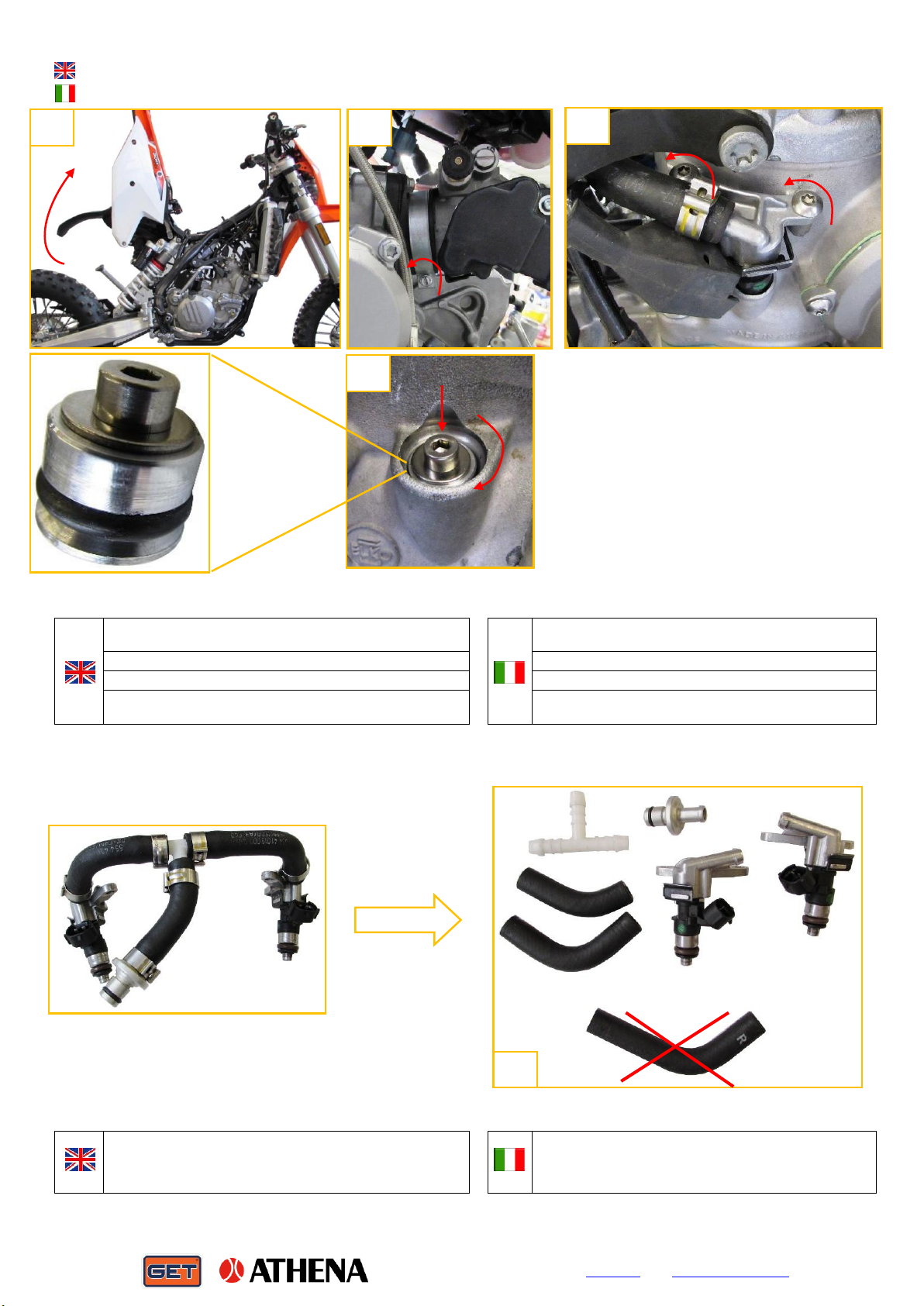
Kit contents GK-ECULMB48M-00XX:
(“XX” bike model e.g. KTM 300 EXC TPI=08)
ECU racing GET, Map switch and harness, WiFiCOM,
installation manual
Kit contents GK-KIT2TI-00XX:
(“XX” bike model e.g. KTM 300 EXC TPI=00)
Injectors support kit, ECU racing GET, Map select and
harness, WFCOM, installation manual
Contenuto GK-ECULMB48M-00XX:
(“XX” modello moto Es. KTM 300 EXC TPI= 08)
ECU Racing GET, cablaggio e selettore mappa, WiFiCOM,
manuale istruzioni.
Contenuto GK-KIT2TI-00XX:
(“XX” modello moto Es. KTM 300 EXC TPI= 00)
Kit supporto iniettori, ECU Racing GET, cablaggio e selettore
mappa, WFCOM, manuale di istruzioni.
1-Disconnect the positive battery pole and unhook the
ECU connector
1- Disconnettere il polo positivo della batteria (sotto sella) e
togliere la ECU originale sganciandola dal connettore
ATTENTION: if you have the GET injectors support
kit, procced with “INJECTOR SUPPORT
INSTALLATION “
ATTENZIONE: se si dispone di un kit sopporto iniettori
GET, procedere con “INSTALLAZIONE SUPPORTO
INIETTORI”
2- pass the cable tie provided under the OEM harness
2- Passare la fascetta fornita sotto il cablaggio originale
3- connect the GET ECU and fix it by the cable tie
3- connettere la ECU GET e fissare il connettore con la
fascetta precedentemente passata sotto i cavi
4- When you put the saddle, the ECU must be in the
middle of saddle protuberances
4- rimontare la sella ponendo attenzione che la ECU GET
stia esattamente tra le protuberanze del sotto sella
1
PUSH
2
1
2
3
4
GD-MIP-0039-AC_rev02 athena.eu sales.get@athena.eu
I
IN
NJ
JE
EC
CT
TO
OR
R
S
SU
UP
PP
PO
OR
RT
T
I
IN
NS
ST
TA
AL
LL
LA
AT
TI
IO
ON
N:
:
I
IN
NS
ST
TA
AL
LL
LA
AZ
ZI
IO
ON
NE
E
S
SU
UP
PP
PO
OR
RT
TO
O
I
IN
NI
IE
ET
TT
TO
OR
RI
I:
:
1-Remove the saddle, fuel tank, exhaust and ECU to lift the
back frame
1- Togliere sella, serbatoio, scarico ed ECU, per poter
alzare il telaio posteriore
2- Remove the throttle body
2- Togliere corpo farfallato
3- Remove the injectors
3- Togliere gli iniettori dalle sedi
4- Put the injectors cap and tighten the screw to enlarge the
o'ring and obtain the max mechanical seal
4- applicare i tappi iniettori e stringere la vite per allargare
l’OR e fare la massima tenuta
5- remove from the bike the “injector group” and disassemble it
like the photo. The fuel hose will not be needed (F) in the next
step
5- togliere dalla moto il “gruppo iniettori” e disassemblarlo
come in foto. Il tubo benzina più lungo (F) non verrà
utilizzato per il prossimo passaggio.
1
2
2
3
4
1
5
NON USARE
DO NOT USE
A
B
C
D
E1
F
E2
GD-MIP-0039-AC_rev02 athena.eu sales.get@athena.eu
6- Remove from the bike the intake flange, the reed valve and
disassemble it like the photo.
6- Togliere la flangia di aspirazione, il pacco lamellare e
disassemblarli come in foto
7- Fix the O-Ring (L) on the GET injector support
7- Applicare O-Ring (L) su supporto iniettori GET
8- Put the reed valve (G) on the GET injector support
8- Applicare pacco lamellare (G) su supporto iniettori GET
9- Fix the reed valve with the OEM screws (H)
9- Fissare pacco lamellare con le viti OEM (H)
10-Fix the injectors on the support like in the picture with the
spacers and screws provided
10- Fissare gli iniettori sul supporto come in foto utilizzando
distanziali e viti fornite a corredo
11-Fix the fuel hoses like the photo, (material reference step
5). Where necessary use the metal band and the fuel hose
provided.
11-Fissare i tubi benzina come in foto, (riferimento
materiale passaggio 5). Dove necessario utilizzare le
fascette metalliche ed il tubo benzina fornito a corredo
NON USARE
DO NOT USE
6
G
H
L
M
7
8
9
L
G
H
10
11
E2
E1
DISTANZIALI
SPACERS
D
FORNITO DA “GET”
PROVIDED BY “GET”
A
B
C
GD-MIP-0039-AC_rev02 athena.eu sales.get@athena.eu
12- Montare il supporto iniettori
“GET” e la flangia aspirazione,
utilizzando le viti M6x30 fornite e la
guarnizione OEM
Riassemblare la moto (serbatoio,
connettori iniettori, corpo farfallato,
air box –telaio posteriore, scarico,
sella)
12- Fix the injector support GET and
the intake flange with the provided
screws M6x30 and the OEM gasket.
Assemble the bike (fuel tank,
injector’s connectors, throttle body,
air box - back frame, exhaust,
saddle).
VITI M6X30 “GET”
“GET” SCREW M6X30
GUARNIZIONE “OEM”
“OEM” GASKET
12
GD-MIP-0039-AC_rev02 athena.eu sales.get@athena.eu
I
ID
DL
LE
E
I
IS
SS
SU
UE
ES
S
-
-
T
TR
RY
Y
T
TP
PS
S
C
CA
AL
LI
IB
BR
RA
AT
TI
IO
ON
N
M
MI
IN
NI
IM
MO
O
I
IR
RR
RE
EG
GO
OL
LA
AR
RE
E
-
-
C
CA
AL
LI
IB
BR
RA
AZ
ZI
IO
ON
NE
E
D
DE
EL
L
T
TP
PS
S
IDLE ISSUES MAY BE CAUSED BY WRONG TPS
CALIBRATION, IN THIS CASE FOLLOW THESE
STEPS TO OBTAIN BEST PERFORMACES FROM
YOUR GET ECU.
TO CALIBRATE TPS, THE ENGINE MUST BE OFF ,
THE GAS TWISTGRIP [A]MUST BE IN FULLY
CLOSED POSITION AND THE ENGINE STOP SWITCH
IN “RUN” POSITION
SE SI MANIFESTANO IRREGOLARITÀ DI
FUNZIONAMENTO PUÒ ESSERE NECESSARIO
RICALIBRARE IL SENSORE TPS.
PER LA CALIBRAZIONE TPS IL MOTORE DEVE ESSERE
SPENTO ,LA MANETTA DEL GAS [A] DEVE ESSERE
COMPLETAMENTE CHIUSA E L’INTERRUTTORE DI
SPEGNIMENTO MOTORE IN POSIZIONE “RUN”
1- Connect the “WAKE UP CONNECTOR BH002”[B]
1- Collegare il “WAKE UP CONNECTOR BH002”[B]
2- Press and hold the kill push-button for 10 seconds,
don’t touch the twistgrip [A] during the procedure
2- Tenere premuto il pulsante “KILL” per 10 secondi senza
muovere la manetta del gas [A]
3- Remuve the “WAKE UP CONNECTOR BH002”[B] at
the end of procedure
3- Scollegare il “WAKE UP CONNECTOR BH002”[B]
ATTENTION: REMEMBER TO REMOVE “WAKE UP
CONNECTOR BH002”, TO AVOID DISCHARGING THE
BATTERY
THE ECU MUST BE CONNECTED TO THE VEHICLE
HARNESS WITH THE WAKE UP CONNECTOR
CONNECTED TO BE PROGRAMMED .
ATTENZIONE: RICORDARSI DI SCOLLEGARE IL “WAKE
UP CONNECTOR BH002”PER NON SCARICARE LA
BATTERIA
LA ECU E’ PROGRAMMABILE SOLO SE COLLEGATA AL
CABLAGGIO MOTO CON “WAKE UP CONNECTOR”
COLLEGATO
A
B
GD-MIP-0039-AC_rev02 athena.eu sales.get@athena.eu
E
EN
NG
GI
IN
NE
E
M
MA
AI
IN
NT
TE
EN
NA
AN
NC
CE
E
–
–
S
ST
TA
AR
RT
T-
-U
UP
P
O
OI
IL
L
P
PU
UM
MP
P
F
Fe
ea
at
tu
ur
re
e
v
va
al
li
id
d
w
wi
it
th
h
E
EC
CU
U
f
fi
ir
rm
mw
wa
ar
re
e
M
MB
B2
2T
TP
PI
I0
07
7
o
or
r
n
ne
ex
xt
t.
.
C
Ch
he
ec
ck
k
t
th
he
e
E
EC
CU
U
f
fi
ir
rm
mw
wa
ar
re
e
w
wi
it
th
h
t
th
he
e
W
WF
FC
CO
OM
M
p
pr
ro
ov
vi
id
de
ed
d
M
MA
AN
NU
UT
TE
EN
NZ
ZI
IO
ON
NE
E
M
MO
OT
TO
OR
RE
E
–
–
A
AV
VV
VI
IA
AM
ME
EN
NT
TO
O
P
PO
OM
MP
PA
A
D
DE
EL
LL
L’
’
O
OL
LI
IO
O
F
Fu
un
nz
zi
io
on
ne
e
v
va
al
li
id
da
a
c
co
on
n
f
fi
ir
rm
mw
wa
ar
re
e
c
ce
en
nt
tr
ra
al
li
in
na
a
M
MB
B2
2T
TP
PI
I0
07
7
o
o
s
su
uc
ce
es
ss
si
iv
vi
i.
.
C
Co
on
nt
tr
ro
ol
ll
la
ar
re
e
i
il
l
F
Fi
ir
rm
mw
wa
ar
re
e
c
co
on
n
i
il
l
W
WF
FC
CO
OM
M
i
in
n
d
do
ot
ta
az
zi
io
on
ne
e
COULD BE NECESSARY REPLACE THE TWO
STROKE OIL.
START UP THE OIL POMP IF THE OIL HOSE
(FLEXIBLE) IS DISCONNECTED OR IF THE OIL TANK
HAS BEEN EMPTYED
PUO’ ESSERE NECESSARIO RABOCCARE/SOSTITUIRE
L’OLIO 2 TEMPI.
AVVIARE LA POMPA DELL OLIO SE IL TUBO DELL OLIO
(FLESSIBILE) 2 TEMPI E’ STACCATO O IL SERBATOIO
DELL OLIO 2 TEMPI E’ STATO COMPLETAMENTE
ESAURITO PER ERRORE
1- Connect the “WAKE UP CONNECTOR BH002”[B]
1- Collegare il “WAKE UP CONNECTOR BH002”[B]
2- Open fully the gas twistgrip.[A]
Keep fully open the gas twistgrip for the necessary time
to push-out all the air bubbles from the oil hose
Close the gas twistgrip only when the operation is finish
2- Portare la manopola dell’acceleratore a pieno gas [A]
Dopo 3 secondi la pompa olio comincia a pulsare.
Mantenere la manopola del gas al 100% per il tempo che si
ritiene necessario alla totale eliminazione dell aria nel tubo
olio 2 tempi.
Chiudere la manopola del gas solo quando si ritiene che
l’operazione sia conclusa.
3- Remove the “WAKE UP CONNECTOR BH002”[B]at
the end of procedure
3- Scollegare il “WAKE UP CONNECTOR BH002”[B]
ATTENTION: REMEMBER TO REMOVE “WAKE UP
CONNECTOR BH002”, TO AVOID DISCHARGING THE
BATTERY
THE ECU MUST BE CONNECTED TO THE VEHICLE
HARNESS WITH THE WAKE UP CONNECTOR
CONNECTED TO BE PROGRAMMED .
ATTENZIONE: RICORDARSI DI SCOLLEGARE IL “WAKE
UP CONNECTOR BH002”PER NON SCARICARE LA
BATTERIA
LA ECU E’ PROGRAMMABILE SOLO SE COLLEGATA AL
CABLAGGIO MOTO CON “WAKE UP CONNECTOR”
COLLEGATO
GD-MIP-0039-AC_rev02 athena.eu sales.get@athena.eu
D
DE
EV
VI
IC
CE
E
W
WI
IF
FI
IC
CO
OM
M
M
Ma
at
tr
ri
ix
x
f
fe
ea
at
tu
ur
re
e
i
is
s
v
va
al
li
id
d
w
wi
it
th
h
E
EC
CU
U
f
fi
ir
rm
mw
wa
ar
re
e
M
MB
B2
2T
TP
PI
I0
07
7
o
or
r
n
ne
ex
xt
t.
.
C
Ch
he
ec
ck
k
t
th
he
e
E
EC
CU
U
f
fi
ir
rm
mw
wa
ar
re
e
w
wi
it
th
h
t
th
he
e
W
WF
FC
CO
OM
M
p
pr
ro
ov
vi
id
de
ed
d
D
DI
IS
SP
PO
OS
SI
IT
TI
IV
VO
O
W
WI
IF
FI
IC
CO
OM
M
L
La
a
f
fu
un
nz
zi
io
on
ne
e
M
Ma
at
tr
ri
ic
ci
i
è
è
v
va
al
li
id
da
a
c
co
on
n
f
fi
ir
rm
mw
wa
ar
re
e
E
EC
CU
U
M
MB
B2
2T
TP
PI
I0
07
7
o
o
s
su
uc
ce
es
ss
si
iv
vi
i.
.
C
Co
on
nt
tr
ro
ol
ll
la
ar
re
e
i
il
l
F
Fi
ir
rm
mw
wa
ar
re
e
c
co
on
n
i
il
l
W
WF
FC
CO
OM
M
i
in
n
d
do
ot
ta
az
zi
io
on
ne
e
1
The management of IGNITION and INJECTION adjustments take place by a matrix TPS, RPM for MAP1 and MAP2, under TUNING menu
2
Select the adjusting points, apply the correction with +and -buttons, then send changes with SET button
3
On request, confirm by pressing YES
4
To adjust the breakpoint, select it, except extremes, and move with +and -, then send with SET button and confirm with YES
1
La gestione delle modifiche di IGNITION e INJECTION avviene tramite una matrice TPS, RPM per MAP1 e MAP2, all'interno del menu TUNING
2
Selezionare i punti in cui si vuole applicare la modifica, utilizzare i tasti +e –per applicare la correzione voluta,quindi inviare le modifiche
premendo il tasto SET
3
Alla richiesta, confermare premendo YES
4
Per modificare il breakpoints, selezionarlo, esclusi gli estremi, e modificarlo con +e –, quindi inviare con il tasto SET e confermare con YES
3
2
4
1
GD-MIP-0039-AC_rev02 athena.eu sales.get@athena.eu
A
AC
CC
CE
ES
SS
SO
OR
RI
IE
ES
S
F
FO
OR
R
G
GE
ET
T
E
EC
CU
UL
LM
MB
B4
48
8M
M
A
AC
CC
CE
ES
SS
SO
OR
RI
I
P
PE
ER
R
G
GE
ET
T
E
EC
CU
UL
LM
MB
B4
48
8M
M
WARNINGS:
AVVERTENZE:
•RACE USE ONLY POWER KIT!!!
•Follow the instructions described in this manual to prevent vehicle damage or loss of performance
•Do not remove the thermostatic valve!!! Removing it may cause damage and malfunction.
•Maintain exhaust valve preload as per OEM manual: 300cc=2.3mm 250cc=2.7mm
•Use only OEM spark plugs; check model in vehicle manual
•Check the good compression ratio of the engine in order to fully exploit the performance of the GET control unit and avoid
malfunctions
•No standard (OEM) air filter and/or exhaust system may loss engine power
•Don’t change or modify the parts supplied by Athena
•Warning: the dash power consumption indicator and FI System Error messages aren’t available when GET ECU is installed.
•Execute the installation when the engine is cold
•During installation avoid that any part installed interferes with hot engine parts, driving parts or with the driver
•No high-pressure washer on the GET ECU
•IL KIT E’ DESTINATO SOLO ED ESCLUSIVAMENTE ALL’ USO AGONISTICO.
•L’inosservanza delle norme presenti nel seguente manuale può compromettere il funzionamento del veicolo e/o perdita di potenza
•Non togliere la valvola termostatica!!! La rimozione di essa può causare danni e mal funzionamenti
•Mantenere il precarico della valvola di scarico come da manuale OEM: 300cc= 2,3mm 250cc=2,7mm
•Utilizzare solo candele OEM; verificare il modello su manuale veicolo
•Verificare il buon rapporto di compressione del motore al fine di sfruttare appieno le prestazioni della centralina GET ed
evitare mal funzionamenti
•Scarico e/o filtro aria diversi dagli originali (OEM) possono causare perdite di potenza
•Non modificare o sostituire il materiale fornito da Athena
•Attenzione: l’indicazione a cruscotto del consumo e gli errori del sistema FI non sono disponibili con la ECU GET
•Eseguire l’installazione a motore freddo
•Evitare nel modo più assoluto che qualsiasi parte installata vada ad interferire con parti calde del motore, organi di guida o
con il pilota
•Evitare getti d’acqua ad alta pressione (idropulitrici) sopra alla centralina GET
GET LC-GPA Multifunction Launch Control
GET LC-GPA Launch Control Multifunzione
GET GPA Switch
Selettore “GET GPA Switch”
Maya Software
Software Maya
GD-MIP-0039-AC_rev02 athena.eu sales.get@athena.eu
Dopo aggiornamento di calibrazione della centralina e regolazione VITE DEL MINIMO della casa costruttrice KTM & HUSQVARNA, GET ha
rilasciato un aggiornamento Firmware (FW) e MAPPA per questa nuova configurazione.
Controllare con il WiFiCOM in dotazione e la App “WiGET” il FW Code della centralina GET e seguire la tabella sotto.
After KTM & HUSQVARNA updates on ECU calibration and idle screw setting, GET released a new Firmware (FW) and map for this new
configuration.
Check with the WiFiCOM provided and our “WiGET” App the FW Code and follow the chart below
✓Necessario
Necessary
Non neccessario
Not necessary
MY 2018
FW Code:
Antecedente MB2TPI10
Prior than MB2TPI10
MY 2018
FW Code:
Uguale o suc. MB2TPI10
Equal or next MB2TPI10
MY 2019
FW Code:
Antecedente MB2TPI10
Prior than MB2TPI10
MY 2019
FW Code:
Uguale o suc. MB2TPI10
Equal or next MB2TPI10
Aggiornamento FW
Update FW
✓

✓

Regolazione vite minimo
Idle screw setting
✓
✓


REGOLAZIONE VITE DEL MINIMO
ADJUST IDLE SCREW
AVVISO IMPORTANTE
WARNING
Avvitare COMPLETAMENTE la vite del minimo,
poi aprirla di:
2,5 giri MY 2018/2019
4,5 giri MY 2020/2021
Screw the idle screw COMPLETELY and then
open it:
2,5 turns MY 2018/2019
4,5 turns MY 2020/2021

This manual suits for next models

2

Other Athena Motorcycle Accessories manuals

Athena S410000500001 User manual

Athena

Athena S410000500001 User manual

Athena P400250100003 User manual

Athena

Athena P400250100003 User manual

Athena GET ECULMB RACE KIT User manual

Athena

Athena GET ECULMB RACE KIT User manual

Athena GET ECULMB RACE KIT User manual

Athena

Athena GET ECULMB RACE KIT User manual

Athena KAWASAKI KX 450 F 2016 User manual

Athena

Athena KAWASAKI KX 450 F 2016 User manual

Athena GET Hourmeter C1 User manual

Athena

Athena GET Hourmeter C1 User manual

Athena GET ECULMB User manual

Athena

Athena GET ECULMB User manual

Popular Motorcycle Accessories manuals by other brands

Yoshimura RACE SERIES Assembly & parts manual

Yoshimura

Yoshimura RACE SERIES Assembly & parts manual

Shark OpenLine user manual

Shark

Shark OpenLine user manual

rizoma PM592 user manual

rizoma

rizoma PM592 user manual

Dynojet Power Commander III installation instructions

Dynojet

Dynojet Power Commander III installation instructions

SW-Motech TRT.00.787.32200/B Mounting instructions

SW-Motech

SW-Motech TRT.00.787.32200/B Mounting instructions

hepco & becker 6617521 01 01 Mounting instructions

hepco & becker

hepco & becker 6617521 01 01 Mounting instructions

W-Tec Ondrejnik user manual

W-Tec

W-Tec Ondrejnik user manual

Cobra Fi2000 PowrPro instruction manual

Cobra

Cobra Fi2000 PowrPro instruction manual

GÜDE GSH 180-TC-2 Translation of the original instructions

GÜDE

GÜDE GSH 180-TC-2 Translation of the original instructions

LITELOK ONE MOTO 108 instructions

LITELOK

LITELOK ONE MOTO 108 instructions

Suzuki 99183-25L00-RED installation instructions

Suzuki

Suzuki 99183-25L00-RED installation instructions

Ducati 97180531A quick start guide

Ducati

Ducati 97180531A quick start guide

OJ JFL-TF Assembly instructions

OJ

OJ JFL-TF Assembly instructions

hepco & becker 654551 01 01 manual

hepco & becker

hepco & becker 654551 01 01 manual

AltRider Hemisphere Saddlebag INSTALLATION & CARE INSTRUCTIONS

AltRider

AltRider Hemisphere Saddlebag INSTALLATION & CARE INSTRUCTIONS

hepco & becker 6504527 00 01 Mounting instructions

hepco & becker

hepco & becker 6504527 00 01 Mounting instructions

KTM SADDLE STAY installation manual

KTM

KTM SADDLE STAY installation manual

Dynojet Power commander V installation instructions

Dynojet

Dynojet Power commander V installation instructions

manuals.online logo
manuals.online logoBrands
  • About & Mission
  • Contact us
  • Privacy Policy
  • Terms and Conditions

Copyright 2025 Manuals.Online. All Rights Reserved.