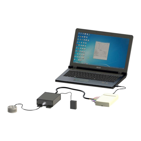
Wireless F/T Installation and Operation Manual
Document #9620-05-Wireless FT-03
Pinnacle
Park
•
1031
Goodworth
Drive
•
Apex,
NC
27539
USA
•
T
el:
+1.919.772.01
15
•
Fax:
+1.919.772.8259
•
www
.ati-ia.com
•
Email:
[email protected] 6
1. Safety
The safety section describes general safety guidelines to be followed with this product, explanation of the
notication found in this manual, and safety precaution that apply to the product. More specic notication are
imbedded within the sections of the manual where they apply.
1.1 ExplanationofNotications
The notications included here are specic to the product(s) covered by this manual. It is expected that the
user heed all notications from the robot manufacturer and/or the manufacturers of other components used
in the installation.
DANGER: Notication of information or instructions that if not followed will result in
death or serious injury. The notication provides information about the nature of the
hazardous situation, the consequences of not avoiding the hazard, and the method for
avoiding the situation.
WARNING: Notication of information or instructions that if not followed could result
in death or serious injury. The notication provides information about the nature of the
hazardous situation, the consequences of not avoiding the hazard, and the method for
avoiding the situation.
CAUTION: Notication of information or instructions that if not followed could result
in moderate injury or will cause damage to equipment. The notication provides
information about the nature of the hazardous situation, the consequences of not
avoiding the hazard, and the method for avoiding the situation.
NOTICE: Notication of specic information or instructions about maintaining, operating,
installation, or setup of the product that if not followed could result in damage to equipment. The
notication can emphasize but is not limited to specic grease types, good operating practices,
or maintenance tips.
1.2 General Safety Guidelines
The customer should verify that the transducer selected is rated for maximum loads and moments expected
during operation. Refer to F/T Transducer Manual (9620-05-Transducer Section—Installation and Operation
Manual) or contact ATI Industrial Automation for assistance. Particular attention should be paid to dynamic
loads caused by robot acceleration and deceleration. These forces can be many times the value of static
forces in high acceleration or deceleration situations.
1.3 Safety Precautions
CAUTION: Do not remove any fasteners or disassemble the Wireless F/T. This
will cause irreparable damage to the Wireless F/T and void the warranty. Leave all
fasteners in place and do not disassemble the Wireless F/T.
CAUTION: Do not remove any fasteners or disassemble transducers without a
removable mounting adapter plate, these include Nano, Mini, IP-rated, and some
Omega transducers. This will cause irreparable damage to the transducer and void the
warranty. Leave all fasteners in place and do not disassemble the transducer.
CAUTION: Do not exert excessive force on the transducer. The transducer is a
sensitive instrument and can be damaged by applying force exceeding the single-axis
overload values of the transducer and cause irreparable damage. Small Nano and Mini
transducers can easily be overloaded during installation, refer to the F/T Transducer
manual (9620-05-Transducer Section) for specic transducer overload values.
