© ATL Agricultural Technology Limited: July 2009
MK3 OUT OF
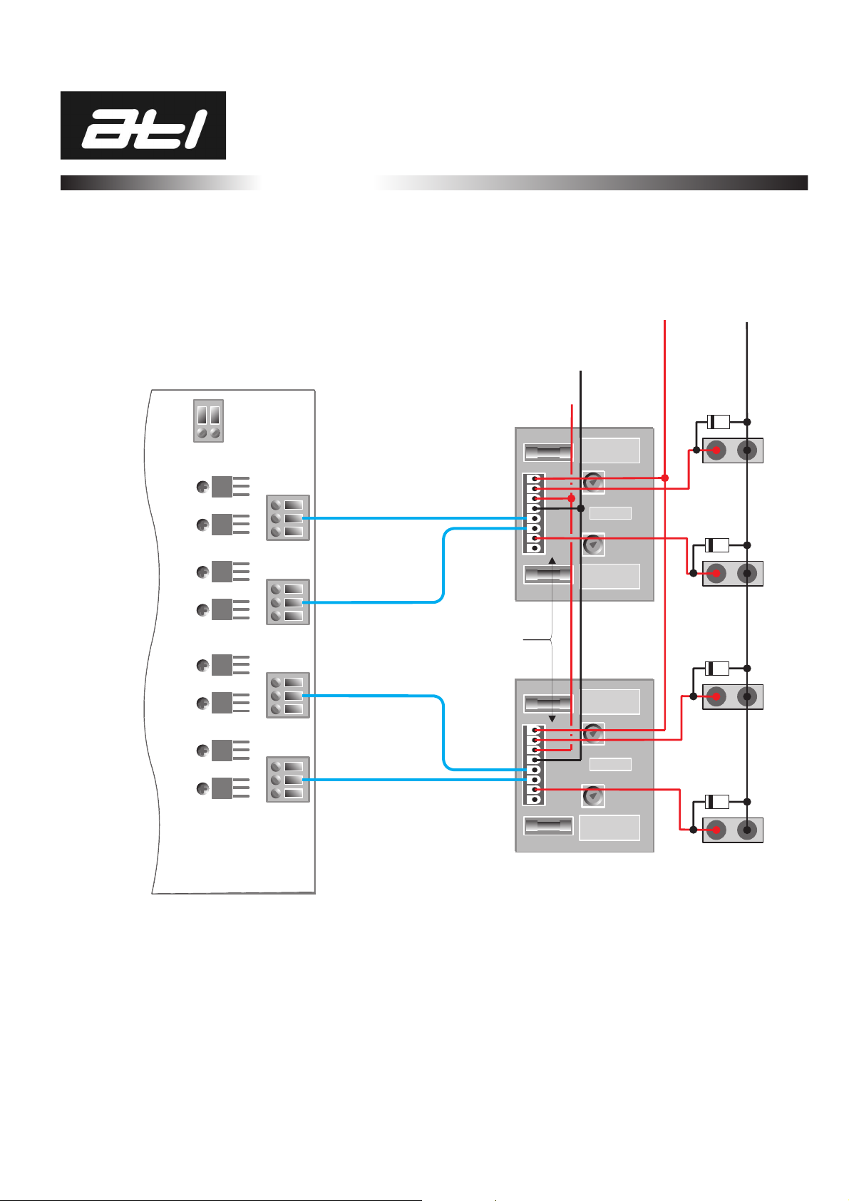
PARLOUR REVIVER
INSTALLATION: 1
DataCables
Out-Of-ParlourInterfaceandFeederCables:
The data cable supplied is ‘twisted pair’configuration especially designed for communications.
No other cables should be used as replacements. Ensure it is connected exactly as shown in the
diagramsand keepthecablerun asshort aspossible.
Do not run near or parallel to, or cross over AC mains supplies or wires carrying switched
current(i.e.milkpumps).
Generallyavoidfluorescentlightingor radiowavesources.
Ideally, data cable should be run through a suitable conduit by itself, esoecially if it is
exposedtotheweather.Sharingconduitwithpowerwiresinvariablycorruptsdata.
Sufficientco-axialcableisprovidedtowire thestallantennasto the Out-Of-ParlourInterface.
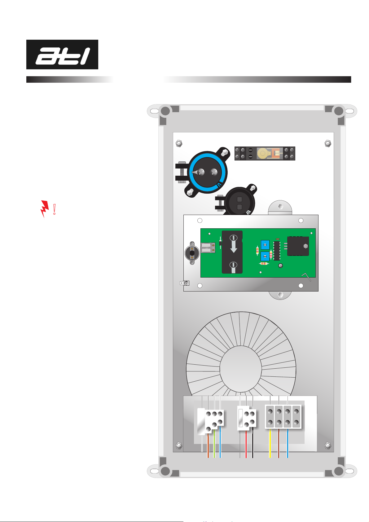
Cable entries into control box MUST be made through the glands provided. Never cut
new entries into the top or sides of the casing. This will automatically invalidate
anywarranties.
ALWAYS use the correct csa (cross sectional area) cable specified in the diagrams.
Environmental Considerations
ATL Out Of Parlour Control equipment is built to the highest specifications to give faithful and
reliable service for years and years. However, it could deteriorate prematurely if a few simple
stepsarenottaken tosafeguardit.
Good ventilation is essential. Fresh air is not only good for animals but also dissipates the
highlycorrosivegasesproducedbysilage,slurry,andsome feedstuffs
PositionOut OfParlourstallswherethereis plentyofair movement.Stale air willcollectin
enclosed corners of even large buildings. Exposed concentrates will deteriorate rapidly
where ventilation is inadequate. Air circulation can be improved by replacing some of the
sheetedcladdingwithYorkshireBoarding.
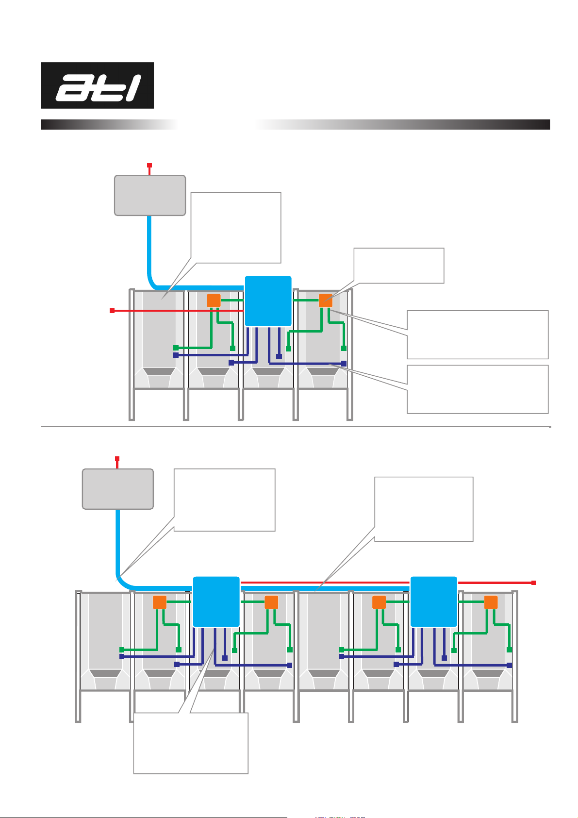
About the ATL Out-Of-Parlour System
The high-speed scanning system addresses each stall in turn seeking a valid ear tag read and so
makes any other form of animal detection unnecessary. Each system contains one (1) Interface
for every 4 feeders, a Console Display Unit, a power supply and a varying number of stalls
depending on system size. Only 1 reader is required per system and this is normally located in
theInterfaceforfeeders1-4.
The Interface contains all of the electronics to detect the presence of an ear tag in a stall,
relay that information back to the Console unit, receive the ration allocation from the
Console and drive the appropriate stall feeder. It can provide the tag reading facility for
almost any number of stalls providing they are not too widely spaced (100 metres absolute
maximum) and drive the first 4 feeder motors. For additional stalls extra Interfaces are required
eachcapableofdrivingupto 4 feeders.
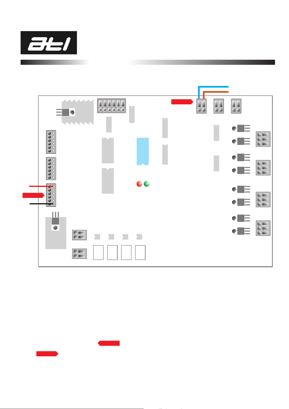
Systems which have second feeders (B) are fitted with an additional, smaller circuit board sited
ontop of themain board.Thiscarriesthedrivecircuitsforthe secondfeeders.
The portable Console unit contains the computing circuitry, stores the herd data and controls the
tag reading and feeding process. It must be connected for the system to operate. Generally, the
Console should be kept and used in a dry environment such as the farm office and may be
connected to the feeder stalls by up to 100meters of special data cable. Power is derived from a
small power supply that is plugged into a standard 13amp mains socket (230v AC) in the office
environment.
n
n
n
n
n
n
n