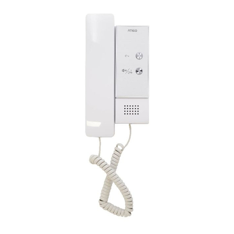
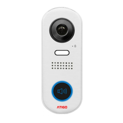
ATIGO A1712 User manual

A1712
User Manual

Parts & Functions
Key functions
Speaker
•Enables communication with the
visitor
Talk/Mon button
•Press for hands free communication
with the visitor
•Press to view the camera in standby
LCD screen
•Display the image of the visitor
Power/Do Not
Disturb
•Show the power status of the system
•Turn on Do Not Disturb mode
Microphone
•Transmit audio to the entry panel or
other monitors
Unlock button
•Press to unlock the door
Connection port
•BUS terminal and monitor addressing
Terminal description
SW+ / SW-
Extra doorbell call button connection port
Ring / GND
Extra buzzer connection port
POW / GND
12~16V extra power connection port
DIP switches
Total 6 bits can be configured
Bit1~Bit5
User code setting switch
Bit6
Video impedance matching switch
L1 / L2
BUS line terminal
Mounting
A. Embed the mounting box intothe
wall
B. Use screws to fasten the
mounting bracket to the mounting
box
C. Connect the 2 wires cables to the
unit
D. Mount the unit onto the mounting
bracket
The suggested installation height is between
145~160 cm from ground.

Main Menu
The Main Menu is the starting point for all
the applications on the monitor.
Function status
To access the Main Menu, touch anywhere
on the monitor’s screen in standby mode.
Icon
Function
Description
Missed call
Visible when there is a new missed call.
Touch this shortcut icon to review the missed called.
Do not disturb
Visible when the function is active
Touch these shortcut icons to enter Call Scene
interface
Call transfer
SIP server configured and
connection active
Touch these shortcut icons to enter SIP server
information interface
SIP server connection
disabled
SIP server connection
active but not connected
Wi-Fi connection active
but not connected
Touch these shortcut icons to enter Wi-Fi settings
interface.
Wi-Fi connection disabled
Wi-Fi configured and
connection active

Intercom mode with another
monitor
Answering a call
1. Touch Talk/Mon button to answer the call. To end the call,
touch the button again.
2. If necessary, during the call, touch to display the
audio/video settings.
3. Touch this button to record the image/video of your call.
4. Touch this button to adjust image colour, brightness and
volume.
5. To unlock the door to the visitor, touch the door lock key
button. An indicator that the door lock has been released will
display on the screen briefly.

Pan & Zoom the view
If you want to see more details, you can
move to the desired position by touching
the UP, DOWN, LEFT, RIGHT arrows & the
CIRCLE on the screen to PAN / TILT and
ZOOM the camera view.
Touch any of the buttons to activate the
PAN / TILT or ZOOM function.
Monitoring
By using an internal CCTV camera, you can
use this function to monitor the interior of
the house (i.e. garage, hallway, garden) or
the entrance.
1. Select the Monitor button from the
Main Menu
2. Select the desired camera from the
Monitor Interface
3. Depending on how many cameras, it is
possible you will have to select next
page “>” to display the rest of the
cameras
4. Touch the Back arrow to return to
previous menu
5. Select any shortcut camera from the list
to activate it
6. If camera belongs to an Entry Panel like
a 2nd entrance, you can activate the
audio for communication.
Call another room or apartment
(Intercom)
It is possible to communicate with another
monitor located in another room of the house
or with a monitor in another apartment.
1. Select Intercom function from the Main
Menu to view a list of available Name list
2. Select the Monitor you wish to call from
the Name list
3. Touch the Name you wish to call

4. You can also select Inner Call to open
communication with another room in the
same house
5. Selecting the Guard Station will call the
concierge unit
6. If the system does display any room
number to call in the Name list, you can
enter the room number directly but
choosing the Input Numbers option.
Note: when a call is received from Entry
Panel while using the intercom function, the
system will prioritise the incoming call and
end any internal call.

View calls recorded
Chose the Call Record function to view
missed calls.
1. Select Call Record to enter the call
recording interface where a list of calls
which includes missed calls, incoming &
outgoing calls are displayed.
2. Select any of the calls on the list to
display it. This will show call date & time
as well as the call source (i.e. main entry
panel, intercom from a different monitor,
etc.)
The call selected will start automatic playback
in case of videos or show the image
captured.
You can use the arrows LEFT & RIGHT to
navigate between images or videos and the
BIN icon to delete them.
Do Not Disturb
If you do not want to be disturbed for example
at night, you can activate the Do Not
Disturb function.
1. Select Call Scene from Main Menu
2. Choose one of the two Do Not Disturb
modes
a. Do Not Disturb 8H
b. Do Not Disturb Always
Do Not Disturb 8H: Calls from the Entry Panel
or other monitors will not sound for 8 hours.
Do Not Disturb Always: Calls from the Entry
Panel or other monitors will not sound until
the setting is turned OFF.
NOTE:
•The indicator changes from GREEN to
RED to indicate that the Do Not Disturb
function is ON.
•On the status bar of Main Menu
icon will be displayed

Divert calls
Calls from the Entry Panel can be diverted to
a mobile phone. This function is only
supported when Wi-Fi or SIP is used.
1. Select Call Scene from Main Menu
2. Choose one of the two Divert Call
modes
a. Divert Cal If No Answer
b. Divert Call Always
Divert Call If No Answer: If the call from the
Entry Panel is not answered within 30
seconds from the monitor receiving it, it will
automatically be diverted to your
programmed smartphone.
Using this more, the monitor will always turn
the screen on and show the image of the
camera while the call is diverted. If the call is
answered while diverted, the diversion will
cease immediately.
Divert Call Always: If a call from the Entry
Panel is received, the monitor will always
divert it straight away to the programmed
smartphone.
Using this more, the monitor will not turn on
and show the image of the camera while
diverting but the option to manually see the
camera is available as normal.
NOTE:
•To use a smartphone via SIP server,
this needs to be previously
programmed.
•When Divert Call Always mode is on, all
calls are immediately diverted
and icon will be displayed
1. Settings
1. Select the Settings option from Main
Menu
2. Select the option required for
customisation from the menu

Ring tone setting
The ring call tone can be set individually to
distinguish different calling sources.
1. Select Call Tune to enter settings
2. Select each individual setting as required
Ring volume
adjust the ringtone volume
Ring time
adjust the ringtone time
Door 1~4
call tone for entry panels 1~4
Doorbell
call tone for doorbell
Intercom
call tone from another
apartment
Inner call
call tone from own apartment
Guard call
call tone from concierge
General setting
This section contains the general settings and
device information.
Date & time setting
In this setting the current date & time can be
modified accordingly.
1. Select the option Date and time to enter
the interface
2. Select the item you wish to change:
Date mode displays the date as:
- month/day/year
- day/month/year
Time mode displays the time as:
- HOUR_12 –12 hours AM/PM
- HOUR_24 –24 hours
Date: select to change current date
Time: select to change current time
Time zone: select to change time zone
Time auto update:
- Disable: set manually
- Enable: is synchronized auto

Language setting
The default language can be customised at any
time.
1. Select Language from General menu
2. Select and touch to confirm the desired
language from the list
NOTE: Please scroll to the next screen using
the RIGHT arrow for more languages.
Setting monitor time
The monitor screen time can be changed and is
available in steps of 30 seconds (i.e. 30s, 60s,
up to maximum 300s).
1. Select Monitor time from General menu
2. Select and touch to confirm the desired
monitor screen time out from the list
Shortcut setting
In this section you can create up to 4 quick
actions that will appear on in the Main Menu
called shortcuts.
1. Select Shortcut setting to enter the
interface
2. Select the shortcut set from the list
3. Select the type of function for which you
want to add the quick action
4. Alternatively, you can Remove the
shortcut if no longer required.
SD Card
If there is an SD card inserted into the monitor,
use this option menu to view information about
it.
1. Select the SD card from the menu to
navigate into it
2. Select to view SD Information or Copy
Image
SD information: SD card capacity
Copy Image: select this option to copy the
recorded images onto the SD card

Screen on in divert setting
When the monitors are set to Divert Call Always
mode, when receiving a call, the monitors will
not display the image. This option allows you to
override this and by setting to Enabled, the
screens will show the caller’s image even when
Divert Call Always mode is ON.
1. Select the RIGHT arrow to go to next
screen
2. Chose Screen on in divert option from the
menu
3. Select to Enable or Disable as required
Restoring to default settings
The restore to default setting allows the user to
set all settings back to factory default.
1. Select the RIGHT arrow to go to next
screen
2. Chose Restore to default option from the
menu
3. Select the option as required from the list
NOTE: There are five options that can be reset,
Clear call record and pictures, Clear Wi-Fi
settings, Restore general settings, Restore
installer settings & Restore factory default.

Installer setting
This section contains the device address and
system settings.
Select Installer option from the menu
DIP Switch addresses
The DIP switches are used to set the user code
for each monitor and maximum are 6 Bits.
Bit-1 ~ Bit-5 are used for addressing. The value
range is from 0 to 31, a total of 32 different
codes for 32 monitors.
Bit-6 is BUS line terminal switch, which should
be set to ON for the last monitor on the BUS
line, otherwise should be OFF
NOTE: When multi monitors are installed in the same apartment, monitors should use the same
code and the master/slave mode should be set on the monitor. (For more details, please refer to
Setting Slave Monitor)
Use reference table for setting the monitors.

Intercom function
To enable or disable the intercom function, enter the Intercom setting and chose the option as
required. Default setting is Enabled
IPC setting
This option is related to the IP cameras that can
be added to the system.
1. Add IP camera by searching
2. Add IP camera manually
Either option it is recommended to add the
IP of the camera, username, password and
channel (port).
3. Add IP camera using DHCP
a. Enable if camera has
dynamic IP
b. Disable if camera has
static IP
To delete a camera, select it, check the status
and chose Delete from the option.

Monitors list
This feature allows to keep and manage a list of
monitors (where available)
[X] –means function is available;
[-] –means function is unavailable;
System settings
This section is reserved.
Software upgrade
The monitor’s software can be upgraded online
or via SD card in the Firmware update
interface, you should select either Server or SD
card to upgrade and chose Check to activate
the process.
Unlock time settings
The unlock time can be changed at any time
and this can be set between 01 and 99
seconds.

Unlock mode setting
There are two modes to unlock
1. Normally open mode
2. Normally closed mode
Reboot
This option allows Rebooting the system or
program the Auto Reboot function.

Wireless settings
1. Select Wireless from the menu
2. Chose to activate the Wi-Fi function
by switching it to ON
3. Enter the Wlan setting interface
4. Find and select your domestic home
network to which you wish to connect
5. Select and enter the Wi-Fi password
for the network selected
6. Chose OK to enable and return to the
Wi-Fi interface screen
7. Select
8. Connect / Disconnect
Register Slave Wi-Fi monitor to Master Wi-Fi monitor
On the master and slave Wi-Fi monitor access the Wireless settings interface
1. Select and enter device manage page
2. Select to enter master / slave registration page
3. On Master chose to register new Slave monitor
4. On Slave chose to register new Master monitor

SIP config
This option enables the ability to divert the call to a mobile using a SIP server.
In Call Scene interface
1. Select one of the two options
a. Divert Call if no answer
b. Divert Call always
In the Wireless settings interface
2. Select and enter the SIP config
3. Select to restore all settings on “SIP config” and create 2 new SIP accounts, one will be
used on the monitor and the 2nd one on the 2Easy APP. When registering, the server will
create and register a default password
4. On the monitor, select and insert newly created SIP account from previous step and it will
register with the server.

SIP tools
SIP tools are designed to help test the divert
function.
1. Select SIP tools to enter the menu
2. Chose SIP call testing to access the testing
page
•SIP call testing count - this setting can
be set between 1~99 and it means that
the test will run automatically the set
value
•Call interval –this setting is set between
1~10 minutes and it means that the
system will the set value between calls
•Retry timing –default is 12 seconds and
is the value of retry in case of failure
•Video quality –setting the value to 0
means that the lowest network speed is
required for the system
3. After all settings have been chose, select
“Start SIP call testing” and the monitor will
start immediately to divert calls to the mobile
set
NOTE: Also available in SIP tools there are the following tools:
- SIP call statistics
- Clear SIP call statistics
- View SIP call logs
- Copy SIP call logs to SD card (if available)
- View registered phones
About
Device type
The device name
S/W Ver
The software version
Serial No
The device’s serial number
Node ID
Node ID number
IP Address
The device’s IP address
H/W Address
The device’s MAC address
Subnet Mask
The device’s subnet mask
Default Route
The device’s default route
DT Address
The device’s code number
M/S Code
If the device is a master or slave
Online
Show the number of sub monitors

Download and Setup 2Easy App
1. Scan above code for iOS or Android, download and install the App. Alternatively search
“2Easy” on your iOS or Android App store.
2. Allow “2Easy” access to Internet connection & camera and on the monitor select SIP
Server icon from the Main Menu
3. Within the 2Easy App, press on the top-right corner [-] to scan QR code shown on the
monitor
4. Once QR code is read and all details are shown on the smartphone, select Save
5. Most of Internet provider do not fully support IPv6 feature, please disable it from within
Settings on your smartphone if your Internet provider does not support it

After the connection is made and the SIP account has login, you should see on the 2Easy app
status bar a Registered message. You can manually register by pressing the register button.
Table of contents
Other ATIGO Intercom System manuals