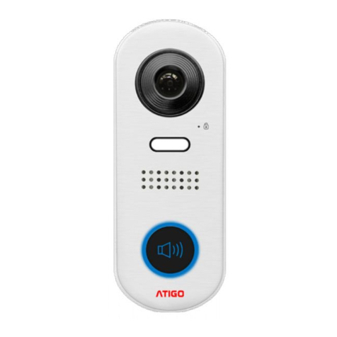
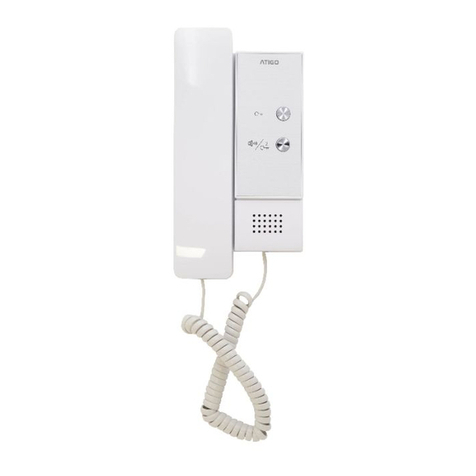
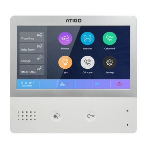
ATIGO A3101 User manual

2 Wire Digital
Video System
Installation Manual

Introduction
The Atigo door entry system is a simple 2
wire solution that can be expanded up to 4
entrance panels and 32 internal monitors.
Programming of the camera module is done
via built in DIP switches and touch keys.
The camera module has built in visual and
audible status indictors as well as white
LED for night view.
Important notes:
Maximum of 4 monitors can be connected
to a single call button
Maximum of 4 monitors can be connected
in daisy chain configuration
Maximum of 8 monitors can be connected
to a single A2200 in distributor mode (DIP
switch 1 OFF)
Maximum of 4 A2200 units can be
connected to single A2200 in raiser mode
(DIP switch 1 ON)
Cable distances
*CAT5e UTP, cores twisted by
colour code.
Twist the cores of CAT5e-UTP as shown in
the image:
•White with colour cores
•Solid colour cores
CABLE TYPE
A
B
C
Twisted Cores
CAT5e*
40
40
30
Belden 8762
or equivalent
60
60
30
Twisted Cable
2 x 0.75 mm2
60
60
30
Twisted Cable
2 x 1.00 mm2
80
70
30

Video camera module A3101
Specifications:
Power supply: 26Vdc (supplied by A2101 /
A2102)
Power Consumption: 1W standby, 5W
active
Unlock Power output: 12Vdc, 250mA
Unlock time: 1~99s
Working temperature: 20ºC ~ +55ºC
Dimensions: 83(H) x 100(W) x 38(D)mm
A3101 Terminals
1. SET
DIP switches for system configuration.
2. JP-LK
Jumper for setting state of the NO contact
3. CN/KMB
Digital display module connection port
4. CN/T-COIL
Not in use
5. BUS
L1, L2 bus line connecting to terminal
BUS(DS) on the power supply
6. CN-LK
+12V 12VDC power output.
LK- Power ground.
LK+ Common contact of the relay.
NO Normally open/closed contact (use
JP-LK jumper to set)
EB+ Exit button connection port.
EB- Exit button connection port.
7. CN/FUN
Not in use
8. CN/WGN
Not in use

DIP switch settings for A3101
The system can be expanded up to 4 entrance
panels and 32 internal monitors
The video module is configured by 6 DIP
switches.
The DIP switches can be modified either
before or after installation. Restarting the
camera module is necessary whenever the
DIP switches have been modified.
DIP switches 1 and 2 are for door station(s)
ID settings.
When multi door stations are installed on the
system, these two DIP switches must be set
correctly.
Door station DIP switch setting:
No.1 = 00 (Default setting)
No.2 = 10
No.3 = 01
No.4 = 11
DIP switch 3 needs to be set to 0 for
mechanical call button operation.
DIP switch 4 is for call button automatic
allocation. Call buttons are automatically
assigned to the indoor units. The default
setting for this DIP switch is 0
DIP switch 5 is for setting door unlock time. 0
is the default setting for one second delay and
1 is the setting for five seconds delay.
DIP switch 6 is for activating keys A and B
which are used for programming camera
module functions (see next section).
The default setting for this DIP switch is 0.
Video module functions and
programming
Restore factory settings
Warning:
All settings will be deleted if the Restore
Factory Setting is activated.
When the Camera Module is in standby, short
out the Exit Button Port (EB+, EB-) and toggle
DIP switch 6 four times. A long Beep will sound
and all three indicators will blink at the same
time meaning the Restore Factory Setting is
in progress.
Once the three Indicators turn off with a
warning sound of a long Beep, it means the
Restore Factory Setting is complete.
Activating touch keys, A and B
Key A and key B cannot be used on the
camera module until activated.
To activate the keys and set the unit to
programming mode, put DIP switch 6 to ON
position.
DIP switch 6 must be set to ON while the
others are set to OFF to program module.
When programming is finished, put DIP switch
6 back to OFF position to go back to standby.

Electric lock mode setting
When the Camera Module is in Programming
mode:
1. Press Key A, the Unlock Indicator will
turn on with the warning sound of a long
Beep followed by a short Beep
2. Press Key A again to select mode
a. Mode = 0 (default)
Normally Open: The Status indicator
blinks once with the warning sound of a
single long Beep
b. Mode = 1
Normally Closed: The Status indicator
blinks twice with the warning sound of a
long Beep followed by a short Beep.
Lock time delay setting
When the Camera Module is in programming
mode:
1. Press Key A. The Unlock indicator turns
on with the warning sound of a long Beep
followed by a short Beep.
2. Press Key B and hold for desired lock
opening time.
The Unlocking Time delay is indicated by the
number of times that the Status indicator
blinks (set in seconds). For example: The
Status indicator blinks four times, that means
the unlocking time is 4 seconds.
Sound setting
When the Camera Module is in programming
mode:
1. Press and hold Key A for 3 seconds to
enter the Sound Option Mode, the Status
indicator will turn on and the current
sound will play.
2. Press Key A again to play the next tune
3. Press Key B to exit.
Sound volume setting
When the Camera Module is in programming
mode:
1. Press Key B to enter Tune Volume
Setting, theTalk indicator will turn on and
play the sound at the current volume.
2. Press Key A to increase/decrease the
volume (loop setting)
3. Press Key B to exit.
Talk volume setting
1. During the conversation, press and hold
Key B for 3 seconds to enter the Talk
Volume Setting.
The Talk indicator will turn on with a long
Beep followed by a short Beep.
2. Press Key A to increase/decrease the
volume (loop setting).
3. Press Key B to exit.

Electric lock (internal power)
Electric lock output is limited to 12Vdc, and a
maximum current of 250mA.
Jumper setting JP-LK:
1-2 Normally closed mode
2-3 Normally open mode
Fail Locked
Fail Unlocked
Electric lock (external power)
1. Open contact output is limited to 24Vdc,
and a maximum current of 1000mA.
2. The jumper must be taken off before
connecting.
3. Set lock type using touch keys A and B
(see module programming)
Fail Locked - Mode = 0 (default)
Fail Unlocked - Mode = 1

Digital keypad module A3202
Digital keypad module is designed as a digital
call module and as a stand-alone access
control keypad for a secure PIN entry with up
to 40 pin codes capacity.
Use programming table for programming user
pin codes and other functions and features.
Use #to confirm and *to cancel.
If no button is pressed for 10 seconds keypad
will automatically exit programming mode
Example of adding new user code: 2525
Enter Master Code #1234#
Enter Location Code C: 20#
Enter user PIN value V: 2525#
Press *to finish and exit
Combination example:
# 1234 # 20 # 2525 #
Press # 2525 # to test and release the lock
Programming Table

Digital display module A3203
Digital display module is also design as a
proximity card reader with up to 320 user tags
capacity. Reader supports 125KHz and
13.56MHz unencrypted RFID tags
Use supplied master tags to add and delete
user tags.
Programming Tags
Add user tags
1. In standby mode present
MASTER CARD ADD tag to card
reader
2. Use keypad to enter room number
new user tag need to be associated
with and press # to confirm.
3. Tap to add all user tags associated
with selected room.
4. Repeat steps 2 and 3 to add more
user tags
5. Present MASTER CARD ADD tag
to finish.
Delete specific user tags
1. In standby mode present
MASTER CARD DELETE tag to
card reader.
2. Present user tag you wish to delete
to card reader.
Or use keypad to enter room
number you wish to remove all user
tags from and press # to confirm.
3. Repeat steps 2 to remove more
user tags.
4. Present MASTER CARD DELETE
tag to finish.
Delete all users and tags
1. In standby mode present
MASTER CARD DELETE tag to
card reader, wait for double beep.
2. Present MASTER CARD ADD tag
to card reader, wait for double
beep.
3. Once more present
MASTER CARD ADD tag to card
reader, wait for single beep.
4. Wait 10 seconds for reader to
return to standby mode.
Program new MASTER CARD tags
1. Make sure all modules are
connected and powered up.
2. Link together wires EB+ and EB –
on audio/video module and wait for
a beep
3. Switch ON and OFF DIP switch 4,
four times, wait for double beep.
4. Wait 10 seconds for reader to
return to standby mode.

Backup and restore
Audio/Video module is design to store
programmed information about user door
numbers, proximity tags and pin codes.
All information stored by the module can be
backed up and restored if necessary.
E.g.If keypad’s Master PIN code is lost and
entire panel need to be reset to default.
Backup procedure
1. Make sure all modules are
connected and powered up.
2. Insert Micro SD card into the
speech module.
3. Press and hold button A on the
speech module for 10 seconds and
release when you hear the beep,
and all lights turn on.
4. Wait until you hear another beep,
and all lights turn off.
5. Back is now complete.
Restore procedure
1. Make sure all modules are
connected and powered up.
2. Insert Micro SD card into the
speech module.
3. Press and hold button B on the
speech module for 10 seconds and
release when you hear the beep,
and all lights turn on.
4. Wait until you hear another beep,
and all lights turn off.
5. Restore is now complete
Restore to factory default
Caution!
When using this procedure all information will
be lost and modules restored to default
factory settings.
You can reset Master PIN code without losing
all information by following backup and restore
procedure.
Once back up procedure is complete make
sure to remove file PASSWORD.BIN from
Micro SD card as this file holds old mater code
information.
Factory default procedure
1. Make sure all modules are
connected and powered up.
2. Link together wires EB+ and EB –
on audio/video module.
3. On Switch ON and OFF DIP switch
6 four times then disconnect wires
EB+ and EB –.
Speech module will beep, and all
indicators will turn on. After about
15 seconds module will beep again,
and all indicators will turn off.
4. All settings are now back to factory
default.

System layout - Distributor mode


System layout - Riser mode


Other manuals for A3101
2
This manual suits for next models
4
Table of contents
Other ATIGO Intercom System manuals