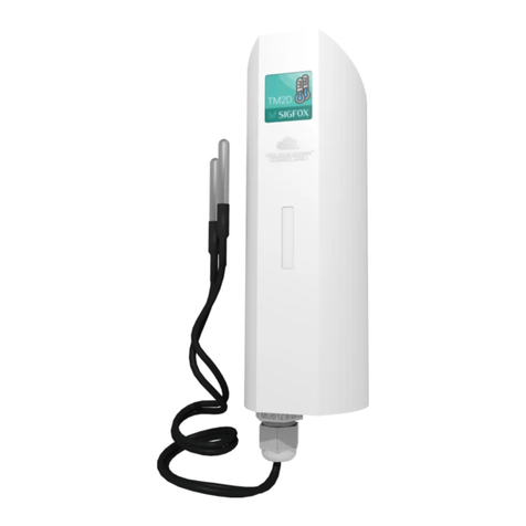
ATIM TM1D-HP Series User manual

ATIM Cloud Wireless
Digital temperature sensor with
contact probe
TM1D-HP
User Guide
Concerned models :
ACW/LW8-TM1D-HP
ACW/LW8-TM1D-HP-5
ACW/SF8-TM1D-HP
ACW/SF8-TM1D-HP-5

1
ATIM_ACW-TM1D-HP_UG_EN_V1.2
TABLE OF CONTENTS
Document version history.................................................................................................................................................3
Disclaimer..........................................................................................................................................................................3
Trademarks and copyright ................................................................................................................................................3
Declaration of compliance................................................................................................................................................4
Environmental recommendations ....................................................................................................................................4
a. Explosive atmosphere 4
b. Environment 4
c. Radio 5
Technical specifications ....................................................................................................................................................6
Housing .............................................................................................................................................................................7
a. Space requirements 7
b. Opening the ACW housing 8
c. Mounting to a support 8
d. Identification 9
e. Placement and installation 11
Operation........................................................................................................................................................................12
a. Periodic mode (shown as ‘Periodical’ in the configuration tool) 12
b. Energy Saver mode 13
ACW configuration tool...................................................................................................................................................14
a. What version of the ACW configuration tool should you use? 14
b. Configuring the LoRaWAN network pairing mode: 15
c. Configuring the Energy Saver mode: 16
d. Configuring periodic mode: 17
e. Factory settings 17
Uplink frame formats......................................................................................................................................................18
a. Sigfox and LoRaWAN 18
b. Example 18
c. Startup sequence: 18
Downlink .........................................................................................................................................................................19
a. Keep-alive frame frequency 19
b. Mode of operation 19
c. Lower threshold 19
d. Upper threshold 19
e. Temperature sampling period 20
f. Temperature offset 20
g. Pairing with LoRaWAN network 20
h. Delta for comfort zone 20
i. Statement period when outside the comfort zone 20

2
ATIM_ACW-TM1D-HP_UG_EN_V1.2
j. Codes reserved for future developments: 20
Connecting the modem ..................................................................................................................................................21
Accessing data on the web (Sigfox and LoRa solutions) .................................................................................................22
a. Viewing probes on the ACW platform 22
b. Registering the modem on the Sigfox network 23
c. Registering the modem on the LoRaWAN network 26
Troubleshooting..............................................................................................................................................................27
The modem cannot be configured via USB or the configuration tool page does not refresh...............................27
Radio data not received .........................................................................................................................................27
Meter index does not increase ..............................................................................................................................27
Modem LED is not flashing.....................................................................................................................................27
Technical support............................................................................................................................................................27

3
ATIM_ACW-TM1D-HP_UG_EN_V1.2
Document version history
Version
Date
Description
Author
0.1
12/11/2015
Created document
YL
0.2
25/11/2015
Created overview
YL
0.3
18/05/2016
Added network
YL
0.4
02/06/2016
Corrections
YL
0.5
10/06/2016
Corrections
YL
0.6
12/12/2017
Added downlink and energy saver mode
CB
0.7
23/01/2018
Update visuals for labels / Sigfox / ACW config
YM
1.0
26/03/2018
Error codes addition + startup sequences
precision + decoding examples of received frames
CB
1.1
24/10/2019
Upgrade from TM2D to TM2D-HP (batteries
modification + PCB unit visual + USB port)
ER
1.2
09/01/2020
Corrections
MD
Disclaimer
The information contained in this document is subject to change without warning and does not represent a
commitment on the part of ATIM radiocommunications. ATIM radiocommunications provides this document ‘as-is’
with no warranty of any kind, express or implied, including but not limited to implied warranties of merchantability or
fitness for a particular purpose. ATIM radiocommunications may make changes and/or improvements to this manual
or to the product(s) or program(s) described in this manual, at any time.
Trademarks and copyright
ATIM radiocommunications®, ACW ATIM Cloud Wireless® and ARM Advanced Radio Modem® are registered
trademarks of ATIM SARL in France. The other trademarks mentioned in this document are the property of their
respective owners.

4
ATIM_ACW-TM1D-HP_UG_EN_V1.2
Declaration of compliance
All ACW Atim Cloud Wireless® products comply with the regulatory requirements of the R&TTE Directive
(1999/5/EC), article 3:
1 SAFETY (Article 3.1a of the 1999/5/EC Directive)
NF EN60950-1 Ed. 2006/A1:2010/A11:2009/A12:2011 (health)
EN62479: 2010 (power <20mW) or EN62311:2008 (power > 20mW)
2 Electromagnetic compatibility (Article 3.1b of the 1999/5/EC Directive)
EN 301489-3 v1.4.1, EN 301489-1 V1.9.2
3 Efficient use of the radio frequency spectrum (Art.3.2 of the 1999/5/EC Directive)
ETSI EN300 220-2 v2.4.1 and EN300 220-1 v2.4.1
Environmental recommendations
a. Explosive atmosphere
Except for the ACW-ATEX line specifically intended for this purpose, do not use ACW radio modems in the presence of
flammable gases or fumes. Using the equipment in such an environment constitutes a safety hazard.
b. Environment
Respect the temperature ranges for storage and operation of all products. Failing to respect these guidelines could
disrupt device operation or damage the equipment. ACW products in IP65 water- and dust-resistant housings may be
placed outdoors but must not be submerged under any circumstances.
Follow the instructions and warnings provided below to ensure your own safety and that of the environment and to
protect your device from any potential damage.

5
ATIM_ACW-TM1D-HP_UG_EN_V1.2
General hazard –Failure to follow the instructions presents a risk of equipment damage.
Electrical hazard –Failure to follow the instructions presents a risk of electrocution and physical injury.
Direct-current symbol
WARNING: do not install this equipment near any source of heat or any source of humidity.
WARNING: for your safety, it is essential that this equipment be switched off and disconnected from mains
power before carrying out any technical operation on it.
WARNING: the safe operation of this product is ensured only when it is operated in accordance with its
intended use. Maintenance may only be performed by qualified personnel.
Waste disposal by users in private households within the European Union. This symbol appears on a product or
its packaging to indicate that the product may not be discarded with another household waste. Rather, it is your
responsibility to dispose of this product by bringing it to a designated collection point for the recycling of electrical
and electronic devices. Collection and recycling waste separately at the time you dispose of it helps to conserve
natural resources and ensure a recycling process that respects human health and the environment. For more
information on the recycling center closest to your home, contact your closest local government office, your local
waste management service or the business from which you purchased the product.
c. Radio
Modems in the ACW line are radio-communication modems that use the ISM (industrial, scientific and
medical) bands, which may be used freely (at no cost and with no authorization required) for industrial,
scientific and medical applications.

6
ATIM_ACW-TM1D-HP_UG_EN_V1.2
Technical specifications
Dimensions
160 x 53 x 53 mm
Antenna
Integrated (¼ wave)
Temperature probe
Digital –Cable length: 2 m
Temperature
-20°C to +55°C (operation)
-40°C to +70°C (storage)
Mounts to
Wall, tube or pole, DIN rail
Housing
IP65
Power supply
2x battery-packs (14,4 Ah)
Weight
210 g
Frequency
865 –870 MHz
Power
25 mW (14 dBm)
Transfer rate
Sigfox: 100 bps
LoRaWAN: 300 bit/s to 10 kbit/s
Current draw
Sigfox*:
LoRaWAN:
Tx mode
60 mA
50 mA
Standby mode
7 µA
7 µA
Rx mode
35 mA
18 mA
* Note that the ACW-TM1D modem is certified class U0 by Sigfox.
Temperature
Range
-55°C │+125°C
Resolution
0.5°C (9 bits)
Precision from -10°C to +85°C
+/- 0.5°C
Precision from -55°C to -10°C
Precision from +85°C to +125°C
+/- 2°C

7
ATIM_ACW-TM1D-HP_UG_EN_V1.2
Housing
a. Space requirements
Maximum cable diameter through cable gland: 7 mm

8
ATIM_ACW-TM1D-HP_UG_EN_V1.2
b. Opening the ACW housing
The housing must be opened to access both the terminal block and the mini-USB
port used to configure the module.
To do this, insert a screwdriver into the slot and tilt it downward to lift the inside
tab (see photo). Then pull on the back panel to separate the two parts of the
housing.
c. Mounting to a support
ACW modems can be mounted on a flat wall, a tube or pole or a DIN rail, depending on the type of installation you
require.
These three types of support frames attach to the rear of the housing.
Mounting on a flat wall (provided):
Mounting on flat wall (provided):
Installation on a tube:
Mounting on a DIN rail:
Opening slot

9
ATIM_ACW-TM1D-HP_UG_EN_V1.2
d. Identification
The Sigfox or LoRaWAN product identifier is visible on the exterior label on the back of the device, on the electronic
card inside and in the status bar in the ACW configuration tool.
For LoRaWAN modems, the communication keys are automatically provided by the network (pairing via ‘Over The Air
Activation’, or OTAA).
Each ATIM ACW product line has a QR Code label visible either on the side or on the front of the product.
ACW-TM1D-HP product label
ACW/XXX-TM1D-HP
Product ID :
Sigfox or LoRaWAN version
Revision n° of the product
(hardware and firmware
technical status)
Sigfox ID or LoRaWAN
DevEUI
Serial number
Datamatrix :
Sigfox ID
or
LoRaWAN DevEUI

10
ATIM_ACW-TM1D-HP_UG_EN_V1.2
This QR code can be easily read with any 2D barcode reader application on a smartphone.
QR Code label of an ACW-TM1D-HP:
Reading this code indicates the following information:
ATIM|ACW/XXX-TM1D-HP|X.X|190114|1|3.0|5.11|XXXXXXXXXXXXXXX
Interpretation:
ATIM
ACW/XXX-
TM1D-HP
X.X
190114
1
3.0
5.11
XXXXXXXXXXXXXXX
Manufacturer
name
Device
reference
Revision
version
Date of
manufacture
Site of
manufacture
Hardware
version
Application
firmware
version
Sigfox ID
or
LoRaWAN DevEUI

11
ATIM_ACW-TM1D-HP_UG_EN_V1.2
e. Placement and installation
Install the modem at least 2 m above the ground and not right against the wall —ideally at least 20 cm away. The
cables must be no longer than 10 m and must be shielded.
For optimal results, we recommend that you place it high up and at least 1 metre away from all metallic objects if
possible (see diagrams below). Note that the antenna is integrated into the housing.
2 m

12
ATIM_ACW-TM1D-HP_UG_EN_V1.2
Operation
The ACW-TM1D measures temperature at time ‘t’ and sends the data by radio on the associated Sigfox or LoRaWAN
network, depending on which model you use.
Two modes of operation are available: Periodic or Energy Saver.
a. Periodic mode (shown as ‘Periodical’ in the configuration tool)
To ensure the most complete telemetry possible, temperature readings are sent on a regular and periodic basis. This
makes it possible to obtain a very precise monitoring curve. In this mode, each reading is sent out by the ACW-TM1D.
In other words, the sampling period is equal to the statement period (= interval at which readings are sent out).
This sampling and statement period is user-configurable, with a minimum value of 10 minutes.
Example of operation in Periodic mode:
On the other hand, because this mode involves regular (and potentially very frequent) radio transmissions, this mode
of operation may consume large amounts of energy, leading to reduced battery life.

13
ATIM_ACW-TM1D-HP_UG_EN_V1.2
b. Energy Saver mode
This mode of operation aims to minimize energy consumption and maximize battery life.
This mode can be configured to send out frames only under certain conditions:
•If temperature readings are stable: a frame is sent out only after a specified period has elapsed (timeout).
•If the temperature variation (in °C) between two consecutive readings is larger than the maximum value
specified by the user.
•If an alert threshold is crossed: a frame is sent out when the temperature reading leaves or re-enters the
comfort zone.
Example of operation in Energy Saver mode:
Phases of operation:
•from 0 to 3 sec: general initialization + USB initialization.
•from 3 to 4 sec: radio initialization.
•from 1 min to 5 min: send out a test frame once per minute.
•at 6 min: send out a keep-alive frame (battery information).
•at 7 min: send out a temperature frame.
Mode of operation (periodic or energy saver) specified by user
•Keep-alive frame sent once per day or once every 4 days.

14
ATIM_ACW-TM1D-HP_UG_EN_V1.2
ACW configuration tool
a. What version of the ACW configuration tool should you use?
For a TM1D with application software version:
Use ACW configuration tool version:
Sigfox: v5.1 or earlier
LoRaWAN: v5.3 or earlier
V3.7.15
Sigfox: v7.1 or earlier
LoRaWAN: v7.1 or earlier
V4.4.0
Download and install the configuration tool ‘setupACW.exe’ at:
https://www.atim.com/download/7887/
When the ACW Configuration Tool is started, the stand-by
window appears on the screen.
Click ‘Help’ at the top left of the window, then click
‘About’ to view the version number of the ACW
Configuration Tool.
Then open the plastic case of your ACW-TM1D-HP module and connect it to your computer with a micro-USB cable.
The product restarts when the USB cable is connected to communicate with the ACW Configurator on your PC. By
disconnecting the USB cable, the product enters its normal operating phase and ends its start phase previously started.
4.4.0

15
ATIM_ACW-TM1D-HP_UG_EN_V1.2
b. Configuring the LoRaWAN network pairing mode:
Applies only to ACW/LW8-TM1D-HP version.
On LoRaWAN networks, there are two pairing methods by which a module can connect to the network.
OTAA (Over The Air Activation):
In this mode, the communication keys are assigned and transmitted over the network every time the module starts
up or requests a connection. This is the mode that is configured by default.
ABP (Activation By Personalization):
In this mode, the communication keys used are the ones loaded on the module at the factory. Every time the module
starts up, these same keys are used.
When you connect the ACW/LW8-TM1D-HP via USB, the ACW configuration tool automatically detects the module’s
factory settings and displays them in the following window:
The default factory setting uses the OTAA mode.
Select LoRaWAN
network pairing
method

16
ATIM_ACW-TM1D-HP_UG_EN_V1.2
c. Configuring the Energy Saver mode:
ACW-TM1D firmware
version
Radio module firmware
version
Network ID
Apply settings
Select mode of
operation
Difference in °C (vs.
last reading sent) If
outside range, send
an alert.
Frequency of
transmission to
network
Lower threshold
Upper threshold
Offset applied to
each reading and to
the displayed value
Temperature sampling
period
Restore the ACW’s
default
configuration
Reload the ACW’s
current
configuration
Select keep-alive frame
frequency

17
ATIM_ACW-TM1D-HP_UG_EN_V1.2
d. Configuring periodic mode:
Once the configuration is complete, do not leave the module connected via USB. This mode of
operation is very energy intensive. When you remove the USB connection without removing the
battery, the module re-initializes itself and automatically returns to normal operation.
e. Factory settings
When it leaves the factory, the TM1D is configured as follows:
- Periodic mode selected by default
Parameters shared by Periodic and Energy Saver modes:
- LoRaWAN pairing: OTAA
- Keep-alive frame sent 1x / day
- Temperature offset: 0°C
- Lower threshold: 20°C
- Upper threshold: 40°C
Parameter for periodic mode:
- Sampling and statement period: 2 hours
Parameters for Energy Saver mode:
- Delta: +/- 2°C
- Sampling period in comfort zone: 2 hours (alert frame sent out if delta value is exceeded or if upper or
lower threshold is crossed)
- Statement period when temperature is stable within comfort zone: 8 hours
- Sampling and statement period outside comfort zone: 2 hours
Select mode of
operation
Lower threshold
Upper threshold
Offset (applied to
each reading and to
the displayed value)
Temperature sampling
+ statement period

18
ATIM_ACW-TM1D-HP_UG_EN_V1.2
Uplink frame formats
a. Sigfox and LoRaWAN
The data are different depending on the type of frame sent out. The frames specific to the ACW-TM1D use the
following format:
Description
Frame format
oct 0 (dec)
oct 0 (hex)
oct1
oct2
oct3
oct4
Keep-alive frame
1
0x01
Supply IDLE voltage
Supply Tx voltage
Test frame
5
0x05
Test counter
Period temperature reading frame
27
0x1B
Digital temperature 1w - sensor
1
Lower threshold was crossed
42
0x2A
Digital temperature 1w - sensor
1
Upper threshold was crossed
44
0x2C
Digital temperature 1w - sensor
1
The temperature is calculated with the following formula: Digital temperature 1w * 0.0625
BEWARE: A temperature value equals to « 0x8000 » indicates a measuring error. This is often due to a loose cable.
b. Example
Example of frame received: (hex) 2C0348
‘Frame type’ = (hex) 2C = 44 => ‘Higher threshold was crossed’
‘Digital temperature 1w - sensor 1’ = (hex) 0348 = 840 => ‘Actual temperature’ = 840*0.0625 = 52.5°C
Example of frame received: (hex) 2AFDD0
‘Frame type’ = (hex)2A = 42 => ‘Lower threshold was crossed’
‘Digital temperature 1w - sensor 1’ = (hex)FDD0 = -560 => ‘Actual temperature’ = -560*0.0625 = -35°C
c. Startup sequence:
At startup, the TM1D transmits 5 frames spaced one minute apart, with a test counter 0x0501, 0x0502, up to 0x0505.
6th frame transmitted is a keep alive frame.
The 7th frame is an application frame containing a temperature and the header 0x1B. This contains the temperature,
but no information on its relative position toward thresholds.
Then the application frames will have the headers 0x1B, 0x2A or 0x2C.

19
ATIM_ACW-TM1D-HP_UG_EN_V1.2
Downlink
This feature is available on ACW-TM1D models that meet the following conditions:
Application software:
Radio firmware:
SIGFOX version
V7.10
or higher
v5931
or higher
LoRaWAN version
V7.10
or higher
v2.3.3
or higher
The USB configuration of these products requires an ACW configuration tool of version 4.4.0 or higher.
The document ATIM_ACW-DLConfig explains how the downlink works and is available at the below link:
https://www.atim.com/download/8182/
The parameters specific to ACW-TM1D-HP models are:
a. Keep-alive frame frequency
Parameter code (Byte 1)
Parameter value (Byte 2)
0x03,
0x00 = Deactivated,
0x04 = every 10 min,
0x05 = every hour,
0x0A = every 2 hours,
0x0B = every 4 hours,
0x0C = every 8 hours,
0x06 = every day,
0x0D = every 2 days,
0x0E = every 3 days,
0x0F = every 4 days,
0x07 = every week (7 days),
0x08 = every month (30 days).
b. Mode of operation
Parameter code (Byte 1)
Parameter value (Byte 2)
0x0A
0x00 = Periodic,
0x01 = Energy Saver.
c. Lower threshold
Parameter code (Byte 1)
Parameter value (Byte 2)
Parameter value (Byte 3)
0x0B
0xYY
0xZZ
For a threshold in °C with a precision in sixteenths of a degree °C, 0xYY and 0xZZ are calculated as follows:
0𝑥𝑍𝑍𝑌𝑌 = 𝑡ℎ𝑟𝑒𝑠ℎ𝑜𝑙𝑑 ×10000
625
The threshold must fall between -55.0°C and +125.0°C.
d. Upper threshold
Parameter code (Byte 1)
Parameter value (Byte 2)
Parameter value (Byte 3)
0x0C
0xYY
0xZZ
For a threshold in °C with a precision in sixteenths of a degree °C, 0xYY and 0xZZ are calculated as follows:
0𝑥𝑍𝑍𝑌𝑌 = 𝑡ℎ𝑟𝑒𝑠ℎ𝑜𝑙𝑑 ×10000
625
The threshold must fall between -55.0°C and +125.0°C.
This manual suits for next models
4
Table of contents
Other ATIM Temperature Controllers manuals
Popular Temperature Controllers manuals by other brands

Efco
Efco 99 501 91 operating instructions

Danfoss
Danfoss MBT 400 installation guide

KMC Controls
KMC Controls STE-9000 Series Quick reference guide

Ascon tecnologic
Ascon tecnologic KR1 quick guide

P.W. KEY
P.W. KEY RK-2001E2-D Operation manual

Johnson Controls
Johnson Controls TE-63xS Series installation instructions