Operating Instructi ons
BKI 109 e
4100-001-04/12
Department
Electronically controlled lubricators
125 cm
3
– battery-operated
applicable to 65 91 006
Page 2 3
Rev. Index Name Schell 18.04.12
Date released Reichert 18.04.12
BKI 109 engl.DOC
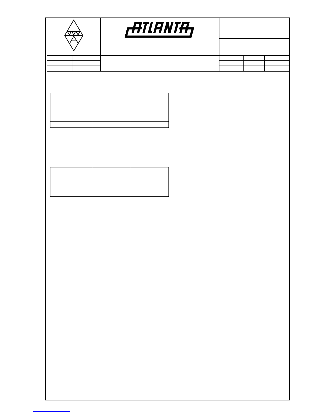
Setting time in
months 1 2 3 6 12 18
DIP switch 1 2 3 4 5 6
Pressure build-
up time in days
The batteries need a certain time to build up the
pressure. They induce an electro-pneumatic reaction
in the built-in nitrogen chamber and transmit the
pressure to the piston via a bellows. This chamber
has to be replaced at the end of the lubricating time.
.
Simply set the desired operating time and mount it.
The resulting pressure build-up times are then as
follows:
Lubrication starts after the appropriate pressure
build-up. The pressure remains built-up even if the
lubricator is switched off for some time.
Therefore lubrication begins immediately after
switching on the lubricator again because the
pressure remains built-up.
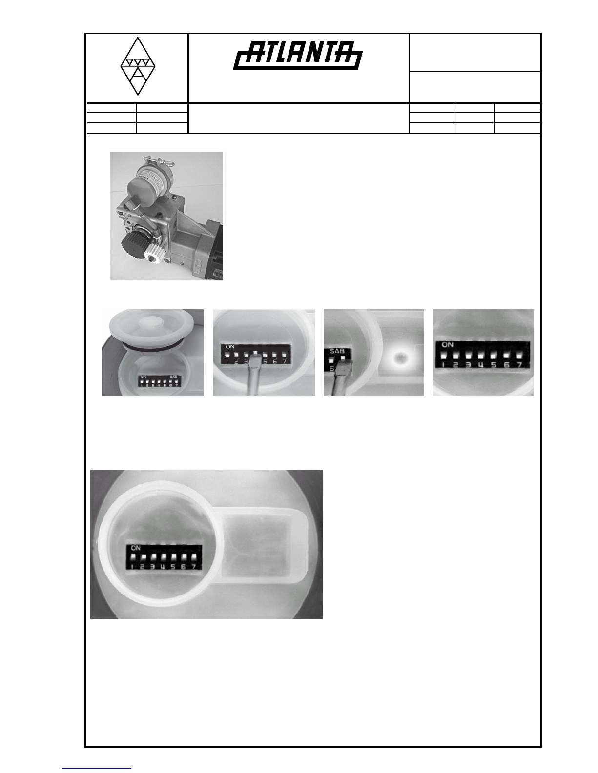
Immediate lubrication and safety check
Set all switches to the "on" position. Pressure build-
up time approx. 6 – 8 hours. Then reset all switches
and set the desired operating time. The signal light
blinks.
Visual control of the pressure build-up by marking the
filling state at the transparent housing. Depending
upon the dosage chosen the piston in the lube
dispenser should move downward from the marking
for more or less time during the pressure build-up.
Important information!
Ambient temperature max. -20°C to max. +50°C.
Avoid electrostatic charging of the lube dispenser
(e.g. due to friction with cloth or strong air currents).
Setting combinations for lube dispenser
DIP switch
position Daily amount of
lubricant Lubricating time
of lubricator
7 = switch for „ON“ - signal light blinks at short intervals
.
6 = 18 M 0.175 cm
All switches
activated 9.00 cm
3
14 days
Combinations:
5 + 4 1.05 cm
Extension with hose or tube is possible up to
approx. 1.5 m for grease lubrication and 5 m
with oil lubrication. In this case the lubrication
charts do not apply because the viscosity of the
lubricant and the length of the hose influence
the flow behaviour of the lubricant. Mind the
correction factors on page 3. There is less
resistance in case of oil filling; therefore we
recommend to use a check valve with 0.2 bars.
The lube dispenser lubricates constantly, i.e.
Supply voltage (2 x 1.5V) 3V
BSV 03 ATEX E 223
Standard type: Varta Electric Power 8008 for
Groups I and IIC T 3
Special type: Varta Industrial Mignon / AA for
Groups I and IIC T 4
II 2G EEx ib IIC T4/T3 Gb
I M2 EEx ib I Mb