4
INSTALLATION
Inspection And Storage:
Immediately upon receipt of shipment, inspect and
check shipping manifest and report to the Transportation
Company’s local agent any damage or shortage.
If the unit is received sometime before it can be used, it
should be inspected, recrated and stored in a dry location.
Location of Unit:
The unit should be mounted in a location where it can be
easily assessible for inspection and maintenance.
Mounting of Base:
Drill and insert six 1/2-13 x 2” (min. length) concrete
anchors into floor. Level base using leveling wedges or
shims and then securely attach base to mounting surface.
If noise level is a factor, the base plate may be filled with
grout through the access hole to reduce vibration and
noise.
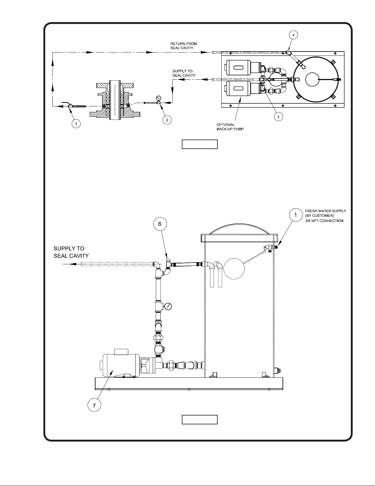
Piping:
Connect fresh water supply to the 3/8” NPT connection
of the float assembly (Figure “B” Pos. 1). Using a suitable
pipe sealer, install item (44) and item (7) pipe nipple/
pressure gauge combination (Figure “A” Pos.2) onto one
side of the packing area (seal cavity) of the dry pit pump.
Next install item (44) and item (6) pipe nipple shut off valve
combination (Figure “A” Pos. 3) on the other side. Install
piping to connect supply water (Figure “A” Pos. 5) from
the pressurized system to the seal cavity (Figure “A” Pos.
2) and return piping from seal cavity (Figure “A” Pos. 3)
to the pressurized system (Figure “A” Pos. 4). NOTE: ALL
pipe joints must be capable of containing 125 psi water
pressure without leaking.
WARNING! BURKS Turbine Pumps are of the
positive displacement type. When the pump
is operating, liquid will be delivered to the
discharge side of the pump. If the discharge
line is blocked or closed, pressure will build
up until the motor stalls, a pump part breaks
or the piping burst. To prevent the possibility
of equipment damage or personal injury, a
pressure relieving device of adequate size
must be incorporated in the discharge side of
the system.
Electrical:
Connect motor control circuit (380 volts, three phase,
50Hz.) to the electric motor junction box (Figure “B” Pos.
7).
WARNING! Failure to connect the motor frame
to the power supply equipment grounding
conductor by using the grounding cord,
green screw or green wire provided may
result in serious electrical shock. All electrical
connections are to be be made by a qualified
electrician.
All pumps with three phase motors MUST be installed
with a magnetic starter which provides 3-leg protection for
motor. Failure to use correct starter will void warranty.
Start the motor and check rotation of the shaft. Be sure
it operates in the direction indicated by the arrow on the
pump casing or frame, as serious damage can result if the
pump is operated in the wrong direction.
Adjusting Supply Pressure:
Allow fresh water supply to fill holding tank to proper
level, start pump and allow for all air to be purged out of
the system. Set the ball valve (Figure “A” Pos.3) so the
pressure gauge shows dry pit operating pressure + 10%.
NOTE: Pressure relief valve (Figure “B” Pos.6) is
factory set and must not be re-adjusted.
Operating Checks:
Open gate valve in discharge line wide open.
Check the pump and piping to assure there are no leaks.
Check and record pressure gauge reading for future
reference.
Check and record voltage, amperage per phase.
MAINTENANCE
Lubrication:
No lubrication is required for the liquid end of any BURKS
turbine pump. Motors are equipped with ball bearings
which are grease-packed and sealed at the factory. No
additional lubrication is required. Base-mounted pumps
have ball bearings in the Power Frame Assembly which
are grease-packed at the factory and have provisions for
re-lubrication as required. Use Chevron SR1 grease, or
equal. For continuous operation, lubricate annually. For
intermittent operation, lubricate every two years. DO NOT
over-lubricate.
Shaft Seal:
The mechanical shaft seal should be replaced if water is
noticed around the motor shaft. Remove case and impeller
and, using two screw drivers to pry on each side, remove
seal stationary seat. Clean seat area of frame, install new
stationary seat with ceramic surface facing out toward
impeller and slide new rotating element over shaft sleeve
with hard carbon surface against ceramic seat. Be sure to
keep all surfaces clean. Lubricating seal parts with water
will help the installation of the seal. Reinstall impeller and
pump case.
Stuffing Box:
Pumps equipped with a stuffing box depend upon a small
amount of water leakage for packing lubrication. Drain
sump below the stuffing box is provided with a 1/4” pipe
tapping for attaching a drain pipe if desired. Stuffing
box should be tightened with pump running. A finger
tight adjustment is generally sufficient. When installing
additional packing, the joints of successive packing pieces
should be staggered to give the best results.