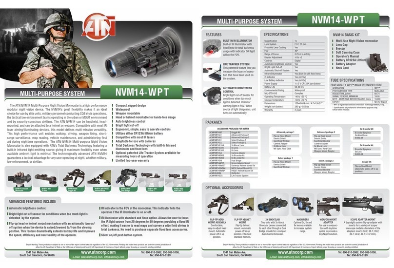
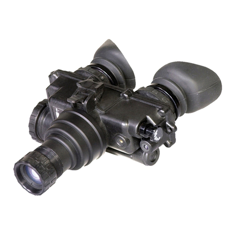
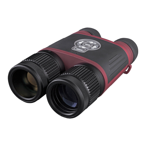
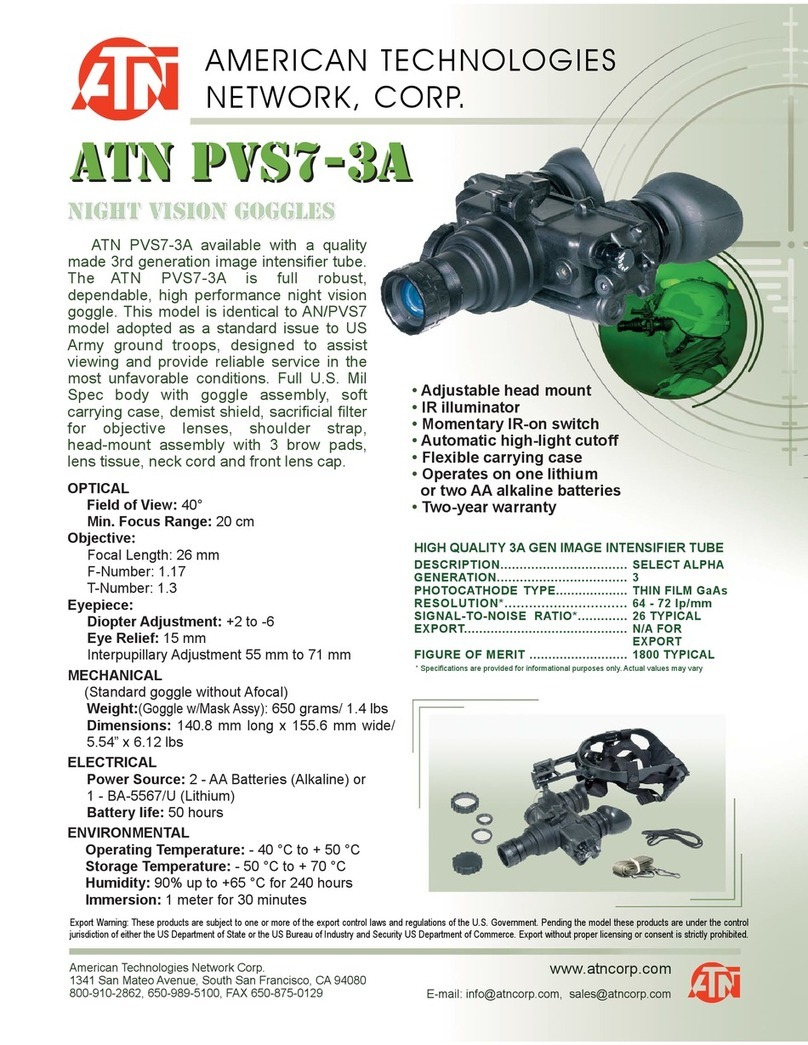
ATN ATN PVS-14 User manual

ATN PVS-14
operator’s manual
Important Export Restrictions! Commodities, products,
technologies and services contained in this manual are
subject to one or more of the export control laws and
regulations of the U.S. Government and they fall under the
control jurisdiction of either the US Department of State
or the US BIS-Department of Commerce. It is unlawful
and strictly prohibited to export, or attempt to export or
otherwise transfer or sell any hardware or technical data or
furnish any service to any foreign person, whether abroad
or in the United States, for which a license or written
approval of the U.S. Government is required, without
first obtaining the required license or written approval
from the Department of the U.S. Government having
jurisdiction. Diversion contrary to U.S. law is prohibited.
OPERATOR’S MANUAL (PVS-14/6015) REVISION 2 - APRIL 2011
ATN 6015
NIGHT VISION MULTI-PURPOSE SYSTEMS

The information in this manual furnished for information use only, is subject to
change without notice, is not to be construed as a commitment by ATN Corp.
ATN Corp. assumes no responsibility or liability for any errors or
inaccuracies that may appear in this book.
© 2011 ATN Corp. All right reserved.
Register your product warranty online at
www.atncorp.com/warranty

a
SAFETY SUMMARY
CAUTIONS
and must be handled carefully at all times to prevent damage.
fingers.
paper can damage the coating.
-
tive lens when the monocular is not in use or when checked out in
daylight conditions.
for use during conditions of extreme darkness. However, the light
from the illuminator can be detected by others when using night
vision devices.
If you use the rubber eyecaps for a long period of time, you may
suffer skin inflammation. If you develop any symptoms, consult a
doctor immediately.
WARNING
Do not carry batteries in pockets containing metal objects such as
coins, keys, etc. Metal objects can cause the batteries to short cir-
cuit and become very hot.
This producT conTains naTur al rubber laTex which may
cause allergic reacTions.
CAUTION:

b
WARNING
Toxic Material
The image intensifier’s phosphor screen contains toxic
materials.
inhaling the phosphor screen material. Do not allow the mate-
rial to come in contact with the mouth or open wounds on the
skin.
immediately with soap and water.
lot of water, induce vomiting, and seek medical attention as
soon as possible.
WARNING
The monocular will not be turned off automatically when flipped
up. The monocular must be turned off by the power switch.
WARNING
The compass illuminator can be seen by others using night
vision devices.
WARNING
Do not use contaminated eyecup or eyeguard. They must be
replaced.
WARNING
careful not to break the protective mask seal around your face.

c
EqUIPMENT LIMITATIONS
To avoid physical and equipment damage when using the ATN
PVS-14 and ATN 6015, carefully read and understand the following
safety precautions.
etc.) to operate. The level of performance depends upon the
level of light.
under trees, in building shadows, etc.
darkened areas.
or smoke.
NOTES
-
to 3 meters when additional illumination is needed.
CAUTION
-
damage.
damage can result.

i
pg.
SAFETY SUMMARY a
CHAPTER 1. INTRODUCTION 1-1
1.1.1. Scope 1-2
1.1.3. Technical Information 1-2
1.1.4. Nomenclature Cross-Reference List 1-2
1.1.5. List of Abbreviations And Acronyms 1-4
1.1.6. Glossary 1-5
1.2.1. Equipment Characteristics, Capabilities,
and Features 1-8
1.2.2. Location and Description Of Major Components 1-8
1.2.3. Equipment Data 1-13
1.3.1. Mechanical Functions 1-15
1.3.2. Optical Functions 1-16
1.3.3. Electronic Circuit Function 1-16
2.1.1. Operator Controls and Indicators 2-2
2.2.1. Preventive Maintenance Checks and
Services Table 2-4
2.2.2. Resolution Check Using the
TS-4348/UV Test Set 2-14
2.2.3. Inspection Criteria for Proper Image Intensifier
Operation 2-16
2.3.1. Unpacking 2-21

ii
2.3.2. Installation of Battery 2-21
2.3.3. Installation of Eyecup Or Eyeguard 2-23
2.3.4. Installation of Demist Shield 2-23
2.3.6. Installation of LIF 2-24
2.3.7. Installation and Adjustment of Headmount 2-25
2.3.8. Installation of Headmount/Helmet
Mount Adapter 2-27
2.3.9. Installation of Helmet Mount to Helmet 2-27
2.3.10.Installation of Headmount with Protective Mask 2-29
2.3.12.Installation of Compass Caution 2-31
2.3.13.Installation of 3x Magnifier 2-33
2.4.1. Hand-Held Operation 2-34
2.4.2. Head Mounted Operation 2-34
2.4.3. Helmet Mounted Operation 2-36
2.4.5. IR Source Operations 2-39
2.4.6. Operation with Compass 2-39
2.4.7. Operation with 3x Magnifier 2-41
2.4.8. Operation with Gain Control 2-41
2.4.9. Preparation for Storage 2-42
2.5.1. Operation in Dusty or Sandy Areas 2-43
2.5.2. Operation in Rainy or Humid Conditions 2-43
2.5.4. Operation in Nuclear, Biological and
Chemical (NBC) Environments 2-44
2.5.5. Operation in Laser Threat Environments 2-44
CHAPTER 3. MAINTENANCE INSTRUCTIONS 3-1
3.3.1. Cleaning the MUNVM 3-6
iii
3.3.2. Headmount Maintenance 3-6
3.3.3. Neck Cord Maintenance 3-8
HOW TO USE THIS MANUAL
You must familiarize yourself with the entire manual before operat-
ing the equipment. Read and follow all warning notices.
The table of contents includes the paragraph number, paragraph
title, and page number. An index provides additional references to
the subject contents.

1-1
CHAPTER 1
INTRODUCTION

1-2
1.1. GENERAL INFORMATION
1.1.1. SCOPE
This manual provides operation and maintenance instructions for
the Multi-Use Night Vision Monocular (MUNVM) ATN PVS-14 and
ATN 6015 hereinafter referred to as the MUNVM. The MUNVM is
a self-contained night vision device that enables improved night
vision using ambient light from the night sk y (moon, stars, sk yglow,
etc.).
ATN NVM-14 and ATN 6015 – Multi-Use Night Vision Monocular
Supplier
American Technologies Network Corp.
1341 San Mateo Avenue
South San Francisco, CA 94080 USA
This item shall conform to design, manufacturing, and performance
requirements and be free from defects in material and workman-
ship for a period of two (2) years from the date of acceptance. If item
is defective, notify ATN or point of purchase contact.
1.1.3. TECHNICAL INFORMATION
For technical information contact ATN Corp. directly at
, or or your point of purchase
contact.
1.1.4. NOMENCLATURE CROSS-REFERENCE LIST
Table 1.1. provides a cross reference of common names and of ficial
terms. Except in the Appendices, the common names will be used.
The of ficial names are used in the Appendices because they reflect
the provisioning nomenclature.

1-3
COMMON NAME OFFICIAL NOMENCLATURE
Battery Battery Nonrechargeable
Battery Cap Cover Battery Retainer
Carrying Case Case, Infrared Equipment
Carrying Case Strap Strapping
Compass Compass Assembly
Demist Shield Lens, Infrared Receiver
Eyeguard Eyeguard, Optical
Eyepiece Lens Cap Cap, Protective, Dust
Headmount Headset Assembly
Headmount/Helmet Mount Adapter Adapter, Headset
Helmet Mount Mount, Viewer
LIF Filter, Infrared Light
Medium Browpad Browpad Assy, Medium
Monocular Monocular Assy
Neck Cord Cord, Fibrous
Objective Lens Cap Cap, Protective, Dust
Shipping and Storage Case Case, Shipping/Storage
Tethering Cord Clip, Retaining
Thick Browpad Browpad Assy, Thick
Thin Browpad Browpad Assy, Thin
3X Magnifier Magnifier Lens Assembly
Bracket, Mounting

1-4
AAL Additional Authorization List
BII Basic Issue Items
CAGEC Commercial and Government Entity Code
cm Centimeters
COEI Components of End Item
CPC Corrosion Prevention and Control-
CTA Common Table of Allowances-
DA Department of the Army
EIC End Item Code
EIR Equipment Improvement Recommendation
FM Field Manual
Hrs Hours
IR Infrared
JTA Joint Table of Allowances
lbs Pounds
LED Light Emitting Diode
LIF Light Interference Filter
MUNVM Multi-Use Night Vision Monocular
NVMPS Night Vision Multi-Purpose System
MTOE Modified Table of Organization and Equipment-
N/A Not Applicable
NBC Nuclear, Biological, and Chemical
NSN National Stock Number
Pam Pamphlet
PASGT Personal Armor System Ground Troops
PMCS Preventive Maintenance Checks and Services
Qty Quantity
Recm Recommended
Rqr Required

1-5
SF Standard Form
TDA Table of Distribution and Allowances-
TM Technical Manual
TOE Table of Organization and Equipment-
U/M Unit of Measure
Vdc Volts, direct current
1.1.6. GLOSSARY
BLACK SPOTS. These are cosmetic blemishes in the image inten-
sifier of the MUNVM or dirt or debris between the lenses.
BRIGHT SPOTS. These defects can appear in the image area of
the MUNVM. This condition is caused by a flaw in the film on the
microchannel plate. A bright spot is a small, nonuniform, bright area
that may flicker or appear constant. Bright spots usually go away
when the light is blocked out and are cosmetic blemishes that are
signal induced.
the headmount to fit different head sizes. The thin browpad (large
head) comes attached to the headmount and the thick (small head)
or medium browpads are stored in the carrying case.
CAUTION. Condition, practices, or procedures that must be ob-
served to avoid damage to equipment, destruction of equipment, or
a long-term health hazard.
of-view either throughout the image area or in parts of the image
area. Under the worst case condition, these lines will form hexago-
nal or square-wave shaped lines.
DARK (OR DARK AREA). A place in which there is very little light.
It does not mean total darkness. Generally, this means conditions
similar to a quarter-moon or starlit night.
DARK-ADAPTED. Having ones eye adjusted to the monocular’s
output under low light conditions.
DIOPTER. A unit of measure used to define eye correction. Adjust-
ments to the diopter adjustment will provide a clearer image in each
eye.

1-6
Edge glow is a bright area (sometimes sparkling) in the outer por-
tion of the viewing area.
EMISSION POINT. A steady or fluctuating pinpoint of bright light in
the image area and does not go away when all light is blocked from
the objective lens of the monocular. The position of an emission
point within the image area of the monocular does not move. An
emission point should not be confused with a point light source in
the distance.
FIXED-PATTERN NOISE. This is a cosmetic blemish in the im-
age area characterized by a faint hexagonal (honeycomb) pattern
throughout the viewing area that most often occurs at high light
levels or when viewing very bright lights. Fixed-pattern noise is in-
herent in the structure of the fiber optics and can be seen in every
image intensifier if the light level is high enough.
FLASHING. This is a defect in the image area of the monocular.
The image appears to flicker or flash.
GAIN. This is the number of times a night vision device amplifies
light input.
IMAGE INTENSIFIER. An electro-optical device that detects and
amplifies ambient light to produce a visual image.
INFINITY FOCUS. Adjustment of the objective lens so that a distant
object, such as a star or the point light on a distant tower, forms the
sharpest image.
INTERMITTENT OPERATION. This is a defect in the image area of
on, the IR source provides additional illumination to enhance exist-
ing light conditions used only for performing nearby tasks.
LIGHT INTERFERENCE FILTER (LIF). This is a light protection fil-
ter for the monocular. Use of this filter will result in a slight reduction
in system gain.
MICROCHANNEL PLATE. A current-multiplying optical disk that
intensifies the electron image produced by the photocathode.

1-7
NOTE. Essential information of special importance, interest, or aid
in job performance.
PHOTOCATHODE. The input optic of an image intensifier that ab-
sorbs light energy and in turn releases electrical energy in the form
of an electron image.
SCINTILLATION. A faint, random, sparkling effect throughout the
image area. Scintillation is a normal characteristic of the image in-
tensifier and should not be confused with emission points. Scintil-
lation is more pronounced under low light conditions. Also called
SHADING. The viewed image should be a full circle. If shading is
present, you will not see a fully circular image. Shading is indicative
of a dying photocathode and is caused by a defective vacuum seal
of the image intensifier. Shading is very dark and you cannot see
an image through it.
-
served to avoid personal injury or loss of life.

1-8
The MUNVM is a hand-held, headmounted, helmet mounted, or
weapon mounted night vision system that enables walking, weapon
firing, short-range surveillance, map reading, vehicle maintenance,
and administering first aid in both moonlight and starlight. Each unit
allows for vertical adjustment (by using head strap), fore-and-aft
adjustment, objective lens focus and eyepiece focus. The monocu-
lar is also equipped with an IR source and a low battery indicator.
The PVS-14 model equipped with a manual gain control.
COMPONENTS
The NVMPS includes the items shown in Figures 1.1., 1.2., 1.3. The
major components are the headmount, helmet mount, monocular,
carrying case, and the shipping and storage case.
a. Monocular
The monocular (see Figure 1.4.) consists of various components
such as an objective lens, an image intensifier (not shown), an eye-
piece lens and a battery cap.
The monocular also uses the accessories listed below:
Demist Shield – The demist shield (Figure 1.1.) is used to
prevent the eyepiece lenses from becoming fogged.
Light Interference Filter (LIF) – The LIF (Figure 1.1.) is to be
used at all times. For replacing the filter the container is also
the wrench. The container/wrench is used to remove and
replace the LIF from the objective lens.
(Figure 1.1.) is supplied to protect the objective lens during
operation in adverse conditions.
Compass – The compass (Figure 1.2.) enables the operator to
see azimuth readings in the monocular.

1-9
FIGURE 1.1. COMPONENTS OF NVMPS
HEAD/HELMET
MOUNT ADAPTER
TETHERING
CORD
HEADMOUNT
THIN
HELMET MOUNT
BATTERY
CARTRIDGE
CARRYING
CASE
OPERATOR’S
MANUAL
MEDIUM AND
-
PADS
LENS
PAPER
CARRYING
CASE STRAP
SACRIFICIAL
DEMIST
SHIELD
EYEGUARD
BATTERY
NECK CORD
OBJECTIVE
LENS CAP
MONOCULAR
CONTAINER

1-10
COMPASS
3X MAGNIFIER
(ADDITIONAL ITEM)

1-11
FIGURE 1.3. SHIPPING AND STORAGE CASES FOR PVS-14 /6015
(SEE FIGURE 1.1. FOR DETAILS)
SHIPPING
AND
STORAGE
CASE

1-12
FIGURE 1.4. MULTI-USE NIGHT VISION MONOCULAR
OBJECTIVE
LENS
EYEPIECE
LENS
GAIN
CONTROL
BATTERY
CAP
Tethering Cord – The tethering cord (Figure 1.1.) enables the
user to attach the compass or 3X magnifier to a button hole or
belt loop to guard against dropping orlosing these items.
3X Magnifier – (Additional Authorized Item) The 3Xmagnifier
(Figure 1.2.) is a lens assembly which can be added to the
monocular to extend the operator’s observation ranges.
The headmount (Figure 1.1.) secures the monocular to the opera-
tor’s head for night viewing and provides freehand support for use
with a weapon, protective mask or other purposes. It is adjustable
and cushioned. The thin browpad used for large heads, comes at-
tached to the headmount; the thick and medium browpads, used for
smaller heads are stored in the carrying case.
c. Helmet Mount
This item (Figure 1.1.), secures the monocular to the Personal Ar-
mor System Ground Troops (PASGT) helmet allowing freehand
support for use with a weapon, protective mask and/or other pur-
poses. The new helmet mount is made of a ruggedized metal. The
old one is made of plastic.
This manual suits for next models
1
Table of contents
Other ATN Binoculars manuals

ATN
ATN ots-14 User manual

ATN
ATN PVS7-CGT User manual

ATN
ATN Night Jaguar Night Vision Binocular User manual

ATN
ATN Night Shadow CGTI User manual

ATN
ATN Night Spirit User manual

ATN
ATN PVS7-HPT User manual

ATN
ATN BinoX 4K 4-16x User manual

ATN
ATN 7x50RF User manual

ATN
ATN VOYAGER 3 User manual

ATN
ATN Night Tiger User manual