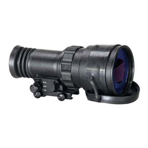
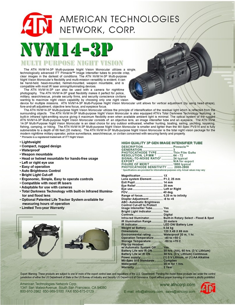
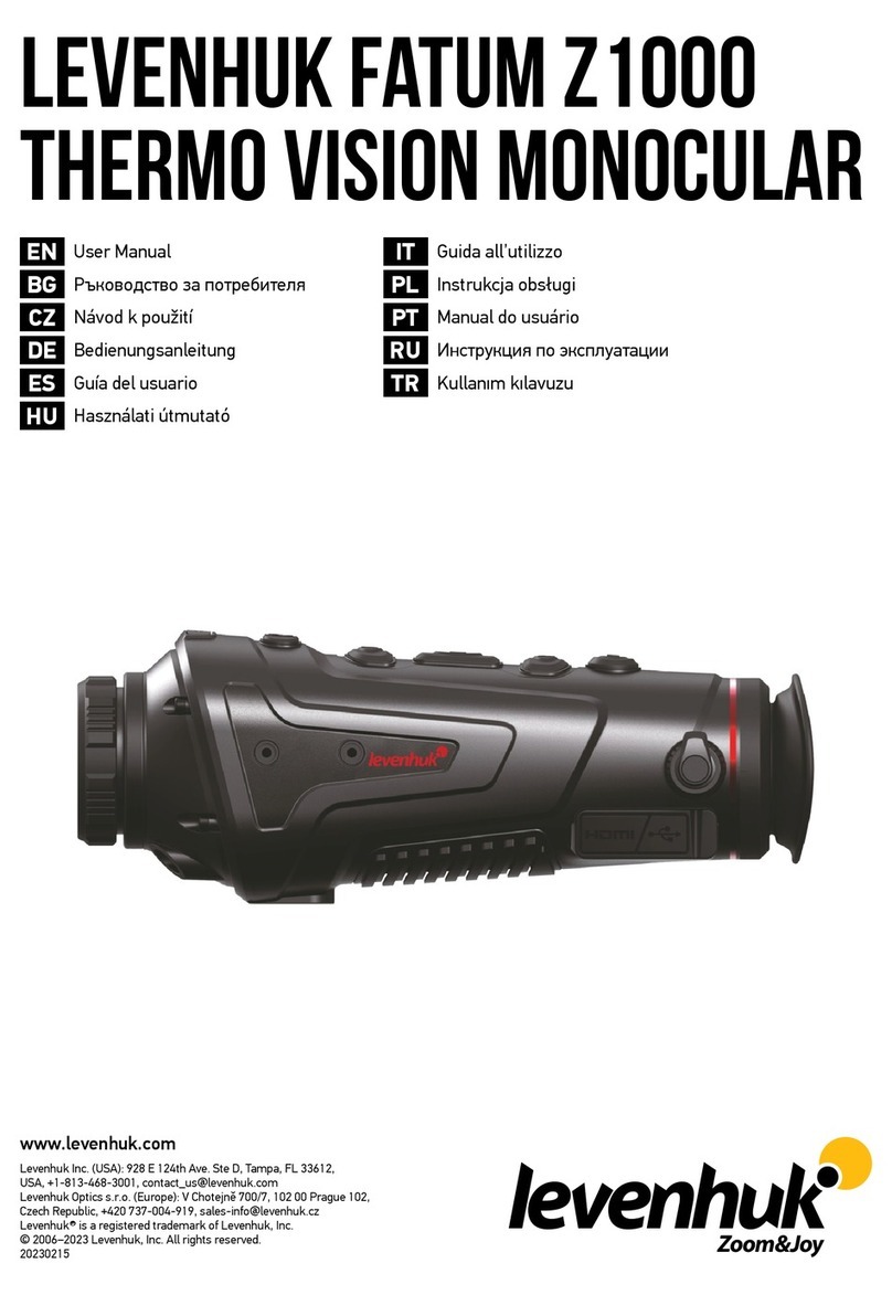
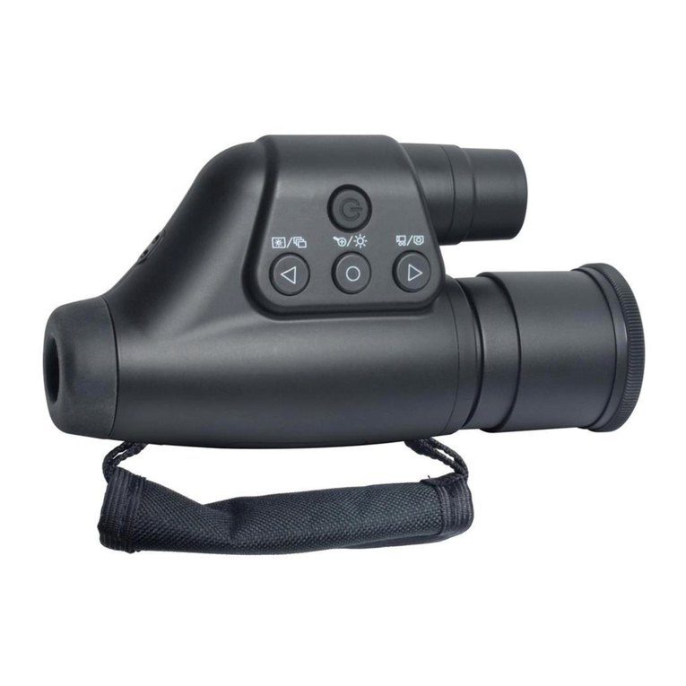
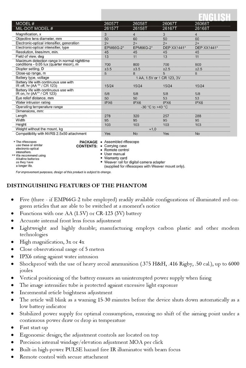
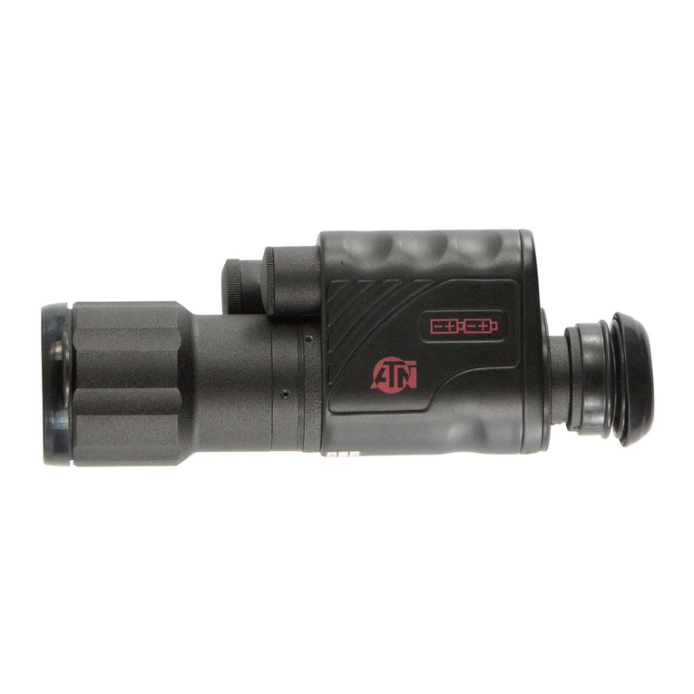
ATN PS-27 User manual

operator’s manual
Important Export Restrictions! Commodities,
products, technologies and services contained in
this manual are subject to one or more of the export
control laws and regulations of the U.S. Government
and they fall under the control jurisdiction of either the
US Department of State or the US BIS-Department
of Commerce. It is unlawful and strictly prohibited
to export, or attempt to export or otherwise transfer
or sell any hardware or technical data or furnish any
service to any foreign person, whether abroad or
in the United States, for which a license or written
approval of the U.S. Government is required, without
first obtaining the required license or written approval
from the Department of the U.S. Government having
jurisdiction. Diversion contrary to U.S. law is prohibited.
NIGHT VISION FRONT SIGHTS
ATN PS-27

Manual ( PS-27 ) Revision 1 - January 2009
The information in this manual furnished for information use only, is subject to
change without notice, is not to be construed as a commitment by ATN Corp.
ATN Corp. assumes no responsibility or liability for any errors or inaccura-
cies that may appear in this book.
© 2010 ATN Corp. All right reserved.

a
SAFETY SUMMARY
STUDY CAREFULLY THIS MANUAL BEFORE TURNING ON
AND OPERATING THIS PRODUCT.
CAUTIONS
The ATN PS-27 night vision unit is a precision electron-optical
instrument and requires careful handling. To provide safe use of
the sight the following instructions should be observed :
•Donotdismantletheunit.
•Keeptheunitclean;protectitfrommoisture,sharptempera-
ture drops and shocks.
•Becarefulnottotouchtheglasssurfaces.Ifyouputfinger-
prints on, or contaminate the glass surfaces, use only clean
and soft materials to clean it.
•Protecttheunitfromexcessivelighting.Donotturnthe
sight on in daylight with the Front Lens Cap off. Do not point
the sight at the bright light source (a fire, car headlights,
lanterns, street lamps, room lights, etc.).
•Donottestthedeviceindaylightconditionsevenwiththe
daylight filter/lens cap on for more than ten (10) minutes.
•Do notleavetheunitin onpositionduringstops in
operation.
•Removethebatteryfromtheunitwhenstoringforperiods
exceeding 3 days. Failure to do so may damage unit.
This producT conTains naTur al rubber laTex which
may cause allergic reacTions.
CAUTION:

b
EQUIPMENT LIMITATIONS
To avoid physical and equipment damage when using the ATN
PS-27, carefully read and understand the following equipment
limitations.
•Theequipmentrequiressomenightlight(moonlight,star-
light, etc.) to operate. The level of equipment performance
depends upon the level of light.
•Nightlightreducesbypassingthroughtheclouds,whileop-
erating under trees, at building shadows, etc.
•Theequipmentislesseffectivewhenviewingintoshadows
and other darkened areas.
•Theequipmentislesseffectivewhenviewingthroughthe
rain, fog, sleet, snow or smoke.
•Theequipmentwillnot“see”throughthedensesmoke.

i
TABLE OF CONTENTS
pg.
SAFETY SUMMARY a
SECTION I. INTRODUCTION 1-1
1.1. General 1-2
1.1.1. Scope 1-2
1.1.2. Reports 1-2
1.1.3. Storage 1-2
1.1.4. Warranty 1-3
1.2. Description and Data 1-5
1.2.1. Description 1-5
1.2.2. PS-27 Standard Components and Optional
Equipment 1-9
SECTION II. OPERATING INSTRUCTIONS 2-1
2.1. Installation Procedures 2-2
2.1.1. Battery Installation 2-2
2.1.2. InstallationonMIL-STD-1913RAIL 2-3
2.1.3. Installation on dayscope objective lens 2-4
2.2. Operating Procedures 2-7
2.2.1. General 2-7
2.2.2. Controls and indicators 2-7
2.2.3. Operating Procedures 2-8
2.2.4. Stowage of PS-27 2-9
2.3. Installation and Use of Accessories 2-10
2.3.1. 7/8”WeaverMount 2-10
2.3.2AdapterforA.R.M.S.mounts 2-11
2.3.3.RemoteControl 2-12
2.3.4.PlatformRing 2-12
2.3.5.LongRailAdapter 2-12
2.3.6. B.A.M. system 2-13
2.3.7. IR450Illuminator 2-13

ii
SECTION III. OPERATIONAL DEFECTS 3-1
3.1. Zeroing Operational Defects 3-2
3.1.1. Shading 3-2
3.1.2. Edge Glow 3-3
3.1.3. Flashing, Flickering, or Intermittent Operation 3-3
3.1.4. Cosmetic Blemishes 3-3
SECTION IV. MAINTENANCE INSTRUCTIONS 4-1
4.1. Preventive Maintenance Checks
and Services (PMCS) 4-2
4.1.1. Purpose of PMCS 4-2
4.1.2. Frequency of performing PMCS 4-2
4.2. Troubleshooting 4-8
4.2.1. General 4-8
4.2.2. Troubleshooting Procedures 4-8
4.3. Maintenance Procedures 4-11
4.3.1. Scope of PS-27 Maintenance 4-11
4.3.2. Cleaning Procedures 4-11
Appendix A. Spare Parts List A-1
Appendix B. How to select Scope Mounting System B-1
Appendix C. Estimation of ambient illumination level C-1
For Technical Information INFO-1

1-1
SECTION I
INTRODUCTION

1-2
1.1 GENERAL INFORMATION
1.1.1. SCOPE
This manual contains instructions for use in operating and main-
taining the ATN PS-27 Night Vision Front Sights. Throughout this
manual, the ATN PS-27 will be referred to as the sights or the
P S -2 7.
1.1.2. REPORTS
Reportsfromtheuseronrecommendationsforimprovementsare
encouraged. Send reports to the address below.
American Technologies Network Corp.
1341 San Mateo Avenue
South San Francisco, CA 94080
(800) 910-2862
(650) 989-5100
(650) 875-0129 fax
www.atncorp.com
info@atncorp.com
1.1.3. STORAGE
Storage of the PS-27 should be done in the factory packing and
after a thorough PMCS as outlined in Chapter 3 of this manual.
This will ensure the sight remains in mission ready condition dur-
ing storage. Batter y should be stored separately from the sight.
The PS-27 should not be placed on the floor, in any area exposed
to high temperatures or direct sunlight. Presence of acid and al-
kaline vapor, as well as of other aggressive admixtures in the air
is unacceptable.

1-3
1.1.4. WARRANTY
2 YEAR PRODUCT WARRANTY
This product is guaranteed to be free from manufacturing defects in material
and workmanship under normal use for a period of 2 (two) years from the
date of purchase. In the event a defect that is covered by the foregoing war-
ranty occurs during the applicable period stated above, ATN, at its option,
will either repair or replace the product, and such action on the part of ATN
shall be the full extent of ATN’s liability, and the Customer’s sole and exclu-
sive remedy. This warranty does not cover a product (a) used in other than
itsnormalandcustomarymanner;(b)subjectedtomisuse;(c)subjectedto
alterations, modifications or repairs by the Customer of by any party other
t h an AT Nw it ho ut pr i o rw r it t en c o ns e n to fAT N ; ( d)s p ec i a lo r d ero r“ c l os e - ou t ”
merchandiseormerchandisesold“as-is”byeitherATNortheATNdealer;
or (e) merchandise that has been discontinued by the manufacturer and ei-
ther parts or replacement units are not available due to reasons beyond the
control of ATN. ATN shall not be responsible for any defects or damage that
in ATN’s opinion is a result from the mishandling, abuse, misuse, improper
storage or improper operation, including use in conjunction with equipment
which is electrically or mechanically incompatible with or of inferior qualit y to
th e pro duc t, a s wel l as f ail ur e to ma in ta in the en vir on me nt al c on di ti on s sp e ci -
fied by the manufacturer.CUSTOMER IS HEREBY NOTIFIED THAT OP-
ERATION OF THE EQUIPMENT DURING DAYLIGHT HOURS OR UNDER
ANY EXCESSIVE LIGHT CONDITIONS MAY PERMANENTLY DAMAGE
THE INT ERNAL COM PONENT S OF THE UN IT AND SAI D DAMAGE WILL
NOT BE COVERED UNDER THIS WARRANTY. This warranty is extended
only to the original purchaser. Any breach of this warranty shall be waived
unless the customer notifies ATN at the address noted below within the ap-
plicable warranty period.
The customer understands and agrees that except for the foregoing war-
ranty, no other warranties written or oral, statutory, expressed or implied,
including any implied warranty of merchantability or fitness for a particular
purpose, shall apply to the product. All such implied warranties are hereby
and expressly disclaimed.
LIMITATION OF LIABILITY
ATN will not be liable for any claims, actions, suits, proceedings, costs, ex-
penses, damages or liabilities arising out of the use of this product. Operation
and u se of th e pro duc t are t he so le res po nsi bilit y of the Custo mer. ATN ’s so le
undertaking is limited to providing the products and services outlined herein
in ac c or da nc e wi th t he terms an d c on di ti on s of th is A gre em en t. T he prov is io n
of produ cts so ld and ser vi ces per for med by ATN to th e Customer s hall not be
interpreted, construed, or regarded, either expressly or implied, as being for
the benefit of or creating any obligation toward any third party of legal entity
outsideATNandtheCustomer;ATN’sobligationsunderthisAgreementex-
tend solely to the Customer.

1-4
ATN’s liability her eunder for damages, re gardless of the form or action,
shall not exceed the fees or other charges paid to ATN by the customer
or customer’s dealer. ATN shall not, in any event, be liable for special,
indirect, incidental, or consequential damages, including, but not lim-
ited to, lost income, lost revenue, or lost profit, whether such damages
were foreseeable or not at the time of purchase, and whether or not
such da mages a rise out of a b reac h of warrant y, a bre ach of agr eem ent ,
negligence, strict liability or any other theory of liability.
PRODUCT WARRANTY REGISTRATION
In order to validate the warranty on your product, ATN must receive a
completed Product Warranty Registration Card for each unit or com-
plete warranty registration on our website at www.atncorp.com. Please
complete the included form and immediately mail it to our Service Cen-
ter: ATN Corporation, 1341 San Mateo Avenue, South San Francisco,
CA 94080.
OBTAINING WARRANTY SERVICE
To obtain warranty service on your unit, End-user must notify ATN ser-
vice department by calling 800-910-2862 or 650-989-5100 or via e-mail
service@atncorp.com to receive a Return Merchandise Authorization
number (RMA).
When returning please take or send the product, postage paid, with a
copy of your sales receipt to our service center, ATN Corporation at the
address noted above. All merchandise must be fully insured with the
correct postage; ATN will not be responsible for improper postage or,
missing or damaged merchandise during shipment.
When sending product back, please clearly mark the RMA# on the
outside of the shipping box. Please include a letter that indicates your
RMA#, Name, Return Address, reason for service return, Contact in-
formation such as valid telephone numbers and/or e-mail address and
proof of purchases that will help us to establish the valid start date of
the warranty. Product merchandise returns that do not have an RMA
listed may be refused or a significant delay in processing may occur.
Estimated Warranty service time is 10-20 business days. End-user/cus-
tomer is responsible for postage to ATN for warranty service. ATN will
cover return postage/shipping to continental USA end-users/custom-
ers after warranty repair only if product is covered by aforementioned
warranty. ATN will return product after warranty service by domestic
ground service and/or domestic mail. Any other requested, required
or international shipping method the postage /shipping fee will be the
responsibility of the end-user/customer.
1-5
1.2. DESCRIPTION AND DATA
1.2.1. DESCRIPTION
A. Purpose. The PS-27 is an effective night vision system that
mounts forward of an existing riflescope/spotting scope (fur-
ther referred to as a scope) adding night vision capabilities
to daytime target acquisition platform. Advisable dayscope
magnificatio n is 1X to 12X (2. 5X to 8X is optim um). The sight is
installed and removed without affecting boresight (permanent
boresight alignment).
NOTE
The PS-27 can be installed also forward of viewfinders of vari-
ous instruments to widen operating illumination range.
B. Principle of Operation. The PS-27 operation is based on the
principle of electron-optical intensification of light. The input
fast catadioptric lens collects available ambient light from
sources such as the moon, stars and skyglow and focuses it
on t he image inten sifi er tu b e photocathode. The tube am p lifies
the light and produces the viewable image projected by the
output lens from the tube screen into the dayscope lens. Thus
the sight provides the capability for operator to see through the
scope at night.
C. Features and Limitations. The PS-27 has the following im-
portant features:
•Availablewithdifferentgenerationimageintensifiertube.
•PoweredbyasinglealkalineA Aor123Alithiumbattery.
•Adjustsforlensfocus.
•Equippedwithmanualgaincontrol(MGCversionofthe
sight) for the best possible image contrast under high and
low light conditions.
•IsmountedonMIL-STD-1913railordayscopelens.
•Batterylifechecksystem.
•Equippedwithremotecontrol.

1-6
•Hasprotectionsystem,whichcutsofftheimageintensifier
when ambient light level exceeds the limit of 40 lux during a 10
seconds period.
•Issubmersibleto10mfor30minutes.
•Filledwithdrynitrogentopreventinternalfogging.
The PS-27 is an effective night vision system designed for night
operations but does have following limitations:
•Thesightrequiressomenightlight(moonlight,starlight,etc.)
to operate. Night light is reduced by such factors as passing
cloud cover and objects that produce shadows.
•Thesightislesseffectiveviewingthroughrain,fog,sleet,
snow, smoke.
•Understarlightconditionslowcontrastenvironments(suchas
snowcovered territory, sandy deserts, large bodies of water or
grassy hills) degrade visibility thereby disguising or masking
changes in terrain.
•Undertoolow-lightconditionsthesightloosessomeofthe
resolution that it has under full moon.
Table 1-1. System Data
ITEM DATA
Magnification Unity (1 X)
Boresight Characteristics:
Accuracy Factory aligned to ½ MOA or better
Retention Permanent to within 1 MOA or better
Repeatability Within ½ MOA
SystemResolutionsubjecttoTubeResolution:
36 to 44 lp /mm 0.38 mrad/lp
45 to 54 lp /mm 0.30 mrad/lp
55 to 64 lp/mm 0.25 mrad/lp
Over 65 lp /mm 0.21 mrad/lp

1-7
Table 1-2. Mechanical Data
ITEM DATA
Dimensions (Length x Width x
Height),mm 177 x 85 x 83
Weight:
without Battery 0.84 kg
withRemoteControl,LightSup-
pressor and Battery 0.91 kg
HeightoftheSightAxisaboveArmRail:
withQuickReleaseMount
with Weaver Mount
withA.R.M.S.#19ACOGMount
41.3 mm
40 mm
49 mm
Table 1-3. Electrical Data
ITEM DATA
Battery One AA (1.5 V) or
123A (3 V)
Consumption Current:
at 1.5 V
at 3.0 V
75 mA
38 mA
Cell Life at 20 ˚C:
AA Alkaline Battery
123A Lithium Battery
32 hours
36 hours

1-8
Table 1- 4. Optical Data
ITEM DATA
Objective Lens Focal Length 80 mm
Objective Lens F/number 1:1.23
Objective Lens T/number 1:1.8
FocusRange 10 m to infinity
Field of View 12˚
Output Lens Exit Pupil Diameter 40 mm
Table 1-5. Environmental Data
ITEM DATA
Operating Temperature -20 to + 50 ˚C
Storage Temperature -50 to +50 ˚C
Humidity 95 % , 25 ˚C to 40 ˚C for 48 hours
IlluminationRequired Natural night illumination (overcast
starlight to moonlight)
Immersion 10 m for 30 minutes

1-9
1.2.2. PS-27 STANDARD COMPONENTS AND
OPTIONAL EQUIPMENT
The PS-27 standard components are shown in Figure 1-1 and pre-
sented in Table 1-6.
Figure 1-1. PS-27 Standard Components
Table 1- 6. PS-27 Standard Components
ITEM DESCRIPTION QTY
1ATN PS-27 1
2Objective Lens Cap 1
3Output Lens Cap 1
4Light Suppressor 1
5RemoteControl 1
6Wrench 1
7Batter y 123A, Lithium 1
8QuickReleaseMount 1
9Shipping /Storage Case 1
10 Operating Manual 1
1
8
10
7
6
2 43
5
9

1-10
Optional items are shown in Figure 1-2 and listed in Table 1-7.
Figure 1-2. PS-27 Optional Equipment
Table 1-7. PS -27 Optional Equipment
ITEM DESCRIPTION PARTCODE
1AdapterforA.R.M.S.Mounts COWSPSAM
2Weaver Mount ACDNPS40MWVR
3ScopeMountingSystem#1
4ScopeMountingSystem#2
5PlatformRing ACWSRTRA
6LongRailAdapter ACWSLRADPT
7Boresight Attachment Mount (B.A.M.)
8IR450-B4Illuminator ACMUIP45B4
1 2
5
3(4)
6
78

2-1
SECTION II
OPERATING INSTRUCTIONS

2-2
2.1. INSTALLATION PROCEDURES
2.1.1. BATTERY INSTALLATION
CAUTION
Ensure the function switch is in the off position before installing
a batter y.
Install the battery as follows:
A. Observe Figure 2-1 for right position of the threaded insert ac-
cording to the battery to be installed.
B. Unscrew the battery compartment cap and check the insert
position.
C. Using furnished wrench change the inser t position in the cap if
necessary.
D. Install the battery into the battery compartment. Follow battery
symbol on the sight body (see Figure 2-2).
E.Replacethebatterycompartmentcap.
Figure 2-1. Insert Positions in the Batter y Compartment Cap
Battery compartment cap Insert
CR 123A
Battery
AA Batter y

2-3
Figure 2-2. Battery Installation
2.1.2. INSTALLATION ON MIL-STD-1913 RAIL
Figure 2-3. PS-27 Installed on MIL-STD-1913 Rail
for ward of Dayscope
NOTE
The optical axis of the PS-27 and the riflescope should be
matched. Difference of the axes position more than 3 mm is not
recommended. Measure the height of the riflescope axis above
the rail. Observe table 1-2 for the sight axis height above the rail.
If the difference in the axis heights of the PS-27 and riflescope is
more than 3 mm it is necessary to replace riflescope mounting
rings or monoblock by proper ones.
Install the PS-27 on MIL-STD-1913 rail as follows:
A. Take off the output lens cap (see figure 1-1) and put it into the
storage case.
QuickReleaseMount
PS-27 Light suppressor Dayscope Plat form ring
LongRailAdapter

2-4
B. Removethelightsuppressorfromthestoragecase.Putitonin
place of the out put lens cap.
C.
To open the sight quick release mount , slide the cam latch for-
ward (arrow A, Figure 2-4) and turn the cam backward (arrow B).
D. Place the sight onto MIL-STD-1913 rail. Be sure to engage the
recoil lug into the groove on the top mounting surface of the
rifle. The light suppressor should cover the riflescope objective
lens.
F. Turn the cam forward pushing the latch to close the mount.
G. The quick release mount may be adjusted to eliminate ex-
cessive play when mounted on the rail by using the provided
wrench (see figure 1-1) to increase/decrease the cam latch
nut. (see figure 2-4)
Figure 2-4. Quick Release Mount
2.1.3. INSTALLATION ON DAYSCOPE OBJECTIVE
LENS
Presented in Table 2-1 optional scope mounting systems are de-
signed to install the PS-27 on riflescope/sporting scope objective
lens.ThesystemsareequippedwitharailformountingoptionalIR
illuminator.

CAUTION
The PS-27 can not be attached to the riflescope/sporting scope
that have a focusing ring on the objective lens housing.

Cam
Latch
Cam
Cam Latch Nut
CLOSED POSITION OPENED POSITION
A
BWrench
CAM ADJUSTMENT
Table of contents
Other ATN Monocular manuals

ATN
ATN OTS10 COLOR-9Hz User manual

ATN
ATN Night Storm 2 User manual

ATN
ATN Night Storm HPT User manual

ATN
ATN Night Leopard User manual

ATN
ATN MO4-1 User manual

ATN
ATN PS14-3A User manual

ATN
ATN OTS 4T Series User manual

ATN
ATN OTIS-14 User manual

ATN
ATN ATN Night Shadow 3 User manual

ATN
ATN MO4-4 User manual