ATS 2330 Series User manual

MAN - PLC Lever Arm Tester - REV: 01
PLC Lever Arm Tester
INSTRUCTION MANUAL
This manual contains important operating and safety information. Carefully read and understand
the contents of this manual prior to the operation of this equipment.
www.atspa.com

REVISED JUNE 2019
Information in this document is subject to change without notice and does not represent a commitment on the part of
Applied Test Systems (ATS).
© Copyright Applied Test Systems 2019
For assistance with set-up or operation, contact the ATS service department. Please have this manual and product serial
number available when you call.
Telephone: +1-724-283-1212.
MAN - PLC Lever Arm Tester - REV: 012

MAN - PLC Lever Arm Tester - REV: 01
i
Manual Contents
A. Introduction..................................................................................................................... 1
A.1 Unpacking ....................................................................................................................................................1
A.2 After Sale Support .......................................................................................................................................1
B. Safety ............................................................................................................................... 2
B.1 For Owners, Operators, and Maintenance...................................................................................................2
B.2 Cautions.......................................................................................................................................................3
C. System Overview ............................................................................................................ 4
C.1 Safety Label Locations.................................................................................................................................4
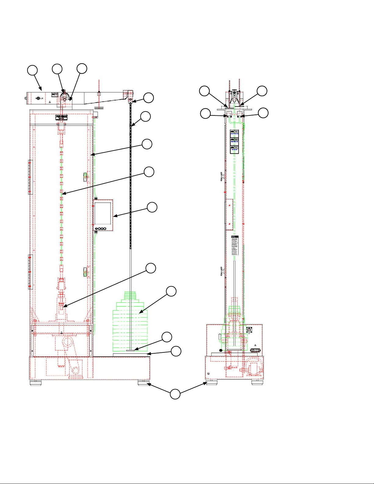
C.2 Equipment Parts ..........................................................................................................................................6
C.3 General Description.....................................................................................................................................7
Product Specications ...........................................................................................................................7
D. Installation ....................................................................................................................... 8
D.1 Unpack and Set Up ......................................................................................................................................8
D.2 Lever Arm Assembly Installation .................................................................................................................8
E. Software Overview........................................................................................................ 10
E.1 Main Screen ...............................................................................................................................................10
Process Time.......................................................................................................................................10
Unload Time.........................................................................................................................................10
Start Button..........................................................................................................................................10
View Button..........................................................................................................................................10
End/Stop Button................................................................................................................................... 11
O State............................................................................................................................................... 11
Running State ...................................................................................................................................... 11
Unload State ........................................................................................................................................ 11
Test Complete State............................................................................................................................. 12
Delay Start State.................................................................................................................................. 12
Sample Break State ............................................................................................................................. 12
E.2 View Screen...............................................................................................................................................12
Test Type.............................................................................................................................................. 13

Unload at End of Test........................................................................................................................... 13
IP Address ........................................................................................................................................... 13
Current Time ........................................................................................................................................ 13
Start Delay ........................................................................................................................................... 13
Done Button......................................................................................................................................... 13
F. Operation........................................................................................................................ 14
F.1 Basic Operation ..........................................................................................................................................14
F.2 Sample Break.............................................................................................................................................15
G. Maintenance.................................................................................................................. 16
G.1 Knife Edges ...............................................................................................................................................16
G.2 V-Blocks ....................................................................................................................................................16
G.3 General Maintenance ................................................................................................................................16
Appendix A: Warranty....................................................................................................... 17
Appendix B: Wiring Diagram............................................................................................ 18
Appendix C: Image Glossary ........................................................................................... 20
MAN - PLC Lever Arm Tester - REV: 01ii

MAN - PLC Lever Arm Tester - REV: 01 | A. Introduction 1
A. Introduction
A.1 Unpacking
Retain all cartons and packing materials until the unit is operated and found to be in good condition. If
damage has occurred during shipping, notify Applied Test Systems (ATS) and the carrier immediately. If it is
necessary to le a damage claim, retain the packing materials for inspection by the carrier.
A.2 After Sale Support
If there are any questions concerning the operation of the unit or software, contact the ATS service
department at +1-724-283-1212. Before calling, please obtain the software revision number and the serial
number from the unit’s data tag or View Screen. A sample data tag is illustrated in Figure A.1, and can be
completed with the unit’s information for easy reference. Please be prepared to give a complete description of
the problem to the ATS service department.
Figure A.1: ATS Sample Data Tag

MAN - PLC Lever Arm Tester - REV: 01 | B. Safety
2
B. Safety
B.1 For Owners, Operators, and Maintenance
Read and understand all instructions and safety precautions listed in this manual before installing or operating
the unit. If there are any questions regarding operation of the unit or the instructions in this manual, contact
the ATS service department at +1-724-283-1212.
In addition to the safety warnings listed on the equipment, warnings are posted throughout this manual. Read
and follow these important instructions. Failure to observe these instructions can result in permanent damage
to the unit, signicant property damage, personal injury, or death.
All ATS equipment is designed to be operated with the highest level of safety. To maintain the safe operation
of this tester, ATS endeavors to educate the operator about safety issues surrounding certain parts of the
machinery. These safety issues are addressed through the use of labeling on the equipment. The following
labels may appear on your test unit:
Burn Hazard/Hot Surface
Electrical Shock/Electrocution
Protective Earth (Ground)
Hand Crush Force From Above
General Danger
No Access for Unauthorized Persons
Read Operator’s Manual
FIgures C.1 and C.2 show the general locations of these labels on the test equipment.

MAN - PLC Lever Arm Tester - REV: 01 | B. Safety
3
B.2 Cautions
The following statements are caution statements. These statements alert the operator to conditions that may
damage equipment. Operators must be aware of these conditions in order to ensure safe operation of the
equipment.
CAUTION: Read and follow all WARNING and CAUTION statements in all related
equipment manuals before attempting to operate this machine. If in any doubt about any
statement or sentence, contact the ATS Service Department or your ATS Sales Engineer.
CAUTION: Installation of electrical devices must be accomplished by competent
personnel and done in accordance with any current local and national codes. Equipment
grounding is REQUIRED.
CAUTION: Before energizing the electrical power to the lever arm tester, turn o all power
switches and place all controls in an OFF or neutral position.
CAUTION: Match serial numbers on test frames, support blocks, and lever arms when
assembling multiple testers.
CAUTION: When stacking weights on test frames, alternate slots at 180°to prevent tip-
over.
CAUTION: Do not place anything under weight elevator that may prevent it from lowering.

MAN - PLC Lever Arm Tester - REV: 01 | C. System Overview
4
C. System Overview
C.1 Safety Label Locations
Figure C.1: Safety Label Location, Side

MAN - PLC Lever Arm Tester - REV: 01 | C. System Overview
5
Figure C.2: Safety Label Location, Front

MAN - PLC Lever Arm Tester - REV: 01 | C. System Overview
6
C.2 Equipment Parts
1. Frame
2. Lever Arm
3. Knife Edge Support Block
4. Safety Guard
5. Weight Pan Shackle
6. Roller Chain
7. Auto Leveling Actuator
8. Auto Leveling Sensor
9. Weight Pan
10. Isolator Pads
11. Shock Pad
12. Drawhead Assembly
13. Break Sensor
14. Break Actuator
15. Load Train
16. HMI
17. Weights
Figure C.3: Basic Lever Arm Front
2433
5
6
1
15
16
12
17
9
11
10
13
38
14
7

MAN - PLC Lever Arm Tester - REV: 01 | C. System Overview
7
C.3 General Description
The ATS lever arm testers have evolved to include the following design features:
• Open frame construction, aids in placement of accessory equipment to suit individual testing needs.
• Lever arm knife edges provide the contact fulcrum for the arm. Knife edges are rotatable with four
edges and are easily replaceable to maintain accuracy.
A variety of optional accessories are available to complete the system to suit many creep/stress rupture test
needs.
Product Specications
Series Load Capacity Ratio Accuracy Power Requirements
2320 10,000 lb. 20:1 (std) 5:1, 10:1, 16:1 (opt) ± 1/2% 230 VAC, 50/60 Hz,
10A, 1 Ø or 115 VAC,
50/60 Hz, 15A, 1 Ø
2330 12,000 lb. 20:1 (std) 10:1, 5:1, 3:1 (opt)
2410 20,000 lb. 20:1 (std)

MAN - PLC Lever Arm Tester- REV: 01 | D. Installation
8
D. Installation
D.1 Unpack and Set Up
1. Carefully remove the shipping crate and packing materials from the tester. Do not discard the packing
materials until all items on the invoice have been accounted for.
2. Use an overhead crane or forklift to remove the test frame and control console from the pallet and position
it in the desired location.
3. Position the test frame and control console to allow ample room for maintenance.
4. Adjust the Isolator Pads on the test frame to approximately level and to provide even support. Verify that
the frame is level by using a level front to back and side to side. Also check the upper crosshead.
CAUTION: Do not allow the isolator mount pads to slide on the oor while moving the
tester. They are not designed to accept slide loading. Damage to the pads may result.
NOTE: When moving the test frame, use moving blankets between components and the
material handling devices and follow accepted moving practices to avoid damage to the
testing machine.
5. Provide electric power from a grounded source. This may be by use of a grounded line cord or by hard
wiring the tester. Follow the National Electric Code requirements and any other local codes in eect. Be sure
the voltage is correct.
CAUTION: Before energizing the electrical power to the testing machine, turn o all power
switches and place all controls in an o or neutral position.
D.2 Lever Arm Assembly Installation
1. Position the knife-edge support block assembly to the top of the test frame. Align the match marks and
install the locating dowels.
2. Install bolts and tighten.
CAUTION: Match the serial numbers on the test frames with the support blocks and lever
arms when assembling multiple testers.
3. Remove or pivot the lever arm safety guards to the side.
4. Check that the knife-edge and V-block mating surfaces are free of dirt, corrosion, or other debris.

MAN - PLC Lever Arm Tester- REV: 01 | D. Installation
9
5. Install the lever arm onto the tester with the V-blocks mated to the knife-edges. Be careful not to damage
knife-edges or v-blocks.
6. Check the lever arm mid-positioning, side by side, by comparing the knife-edges and V-blocks. The lever
arm should pivot freely.
7. Install the safety guards and tighten bolts.
a. Adjust the bolt to allow the arm to freely move. Check through the full movement range.
b. Tighten the jam nut to lock the bolt in place.
c. Re-check step “a”.
8. Check position and operation of shutdown actuator.
a. Install shutdown oating actuator in lever arm above proximity switch.
b. Adjust nuts to provide 0” clearance over the switch with the weight pan side of the lever arm
down all the way.
9. On testers equipped with drawheads for automatic beam leveling:
a. Install automatic beam level oating actuator in lever arm above proximity switch.
b. Adjust nuts to provide 0.5-inch clearance over the switch with the lever arm level.
Figure D.1: Lever Arm Assembly (Dual Ratio Shown)
V- Blocks
Safety Guards
Knife Edge
Counterweight
Locking Screw
Counterweight
(Between Side Plates)
Counterweight
Positioning
Screw
Auto-Leveling
Actuator

MAN - PLC Lever Arm Tester - REV: 01 | E. Software Overview
10
E. Software Overview
E.1 Main Screen
Figure E.1 below shows the Main Screen. This is shown when the PLC Lever Arm is started. It allows you
to setup and run machine cycles.
Process Time
Will only be displayed if a timed test type is selected. It is the amount of time that the system will run the test.
Unload Time
Will only be displayed if “Unload at end of test” is selected. It is the amount of time that the system will unload
the specimen at the end of a test.
Start Button
Used to tell the system that parts are loaded, to start the machine cycle.
View Button
Used to get to additional Set-up for the system.
Figure E.2 shows what the Main Screen looks like when the system is in Run Cycle State. Note the
Figure E.1: Main Screen Figure E.2: Main Screen, Cycle State

MAN - PLC Lever Arm Tester - REV: 01 | E. Software Overview
11
“Remaining Time” being displayed. This will show up for the “Running”, “Unload”, and “Delay Start” states and
will display the time remaining for that part of the cycle. If an indenite test is selected, “Elapsed TIme” will be
displayed.
End/Stop Button
Used to tell the system to nish the cycle. It can also be used anytime the machine is in cycle to stop the
cycle. If pressed while in cycle to stop a cycle a conformation screen is displayed to ask if you are sure that
you wish to abort the cycle.
NOTE: When the machine is in cycle the “Process Time” and “Unload Time” are grayed
out, this means that they can not be changed at this point.
Near the top of the display is a status bar that will show the current state of the machine cycle. Below are the
dierent states in the order that they usually run.
O State
Displays when the system is sitting idle. No cycle is running. The system will sit here until the “Start” button is
pressed. Then it will move into the “Running” state.
Running State
Displays when the machine cycle is running. The system will stay here until the “Process Time” has expired.
Then it will move into the “Unload” state.
Unload State
Displays when the system is in this state it will unload the weight from the load train. The system will stay here
until the “Unload Time” has expired. Then it will go into the “Test Complete” state.
Figure E.3: O State Status Bar Figure E.4: Running State Status Bar
Figure E.5: Unload State Status Bar

MAN - PLC Lever Arm Tester - REV: 01 | E. Software Overview
12
Test Complete State
Displays when the machine cycle has nished. The system will stay here until the “End/Stop” button is
pressed. Once the button is pressed the system will return to the “O” state.
Delay Start State
Only shown if the machine is set-up for a cycle delayed start. This is done on the ”View” screen. The system
will stay here until the “Delay Time” has expired. Then it will start a cycle just as if the operator pressed the
“Start” button.
Sample Break State
Figure E.8 illustrates the screen that is shown if the test type is
“Timed” and if a sample has broken. The “Sample Break” state may
not be seen. It only shows up if the lever-arm drops all the way down
indicating that a sample has broken.
If a sample breaks, you have two choices. You can remove the broken
sample, use the jog buttons to reconnect the load train and level the
lever-arm, then press the “Restart” button to continue the test. Or you
can press the “End/Stop” button to abort the current test. Note, once a
sample breaks, the process timer stops until you either restart or abort
the test.
E.2 View Screen
Figure E.9 illustrates the View Screen. It is shown anytime the “View”
button is pressed on the main screen. It allows access to the rest of
the system parameters.
The screen will show the current version of the software in the PLC and HMI. This is very important
information, and is most often ask for when calling into ATS service.
Figure E.6: Test Complete State Status Bar
Figure E.7: Delay State Status Bar
Figure E.8: Main Screen, Sample Break

13
Test Type
Used to select what type of test to run. The “Timed Test” will run until a time period is nished. The “Indenite
Test” will run until the specimen breaks or the operator stops the test.
Unload at End of Test
This checkbox tells the system to unload the sample at the end of a test.
IP Address
Used to allow someone at a remote location to monitor the system using a VNC viewer program.
Current Time
Allows the operator to set the current time of the system. This time is used in any log les.
Start Delay
Used to allow the system to be set up to start the cycle automatically after a time delay. You can think of it like
a “coee timer”. Just enter the Hours and Minutes you wish to wait before start and press the yellow button.
The button will light to show that a delay has been set. The delay button is a toggle switch, so to turn o a
delay that has been started just press the button again. Note the status of the system will show “Delay Start”
when it is active and the remaining time before start is shown.
Done Button
Will return you to the Main Screen.
MAN - PLC Lever Arm Tester - REV: 01 | E. Software Overview
Figure E.9: View Screen

MAN - PLC Lever Arm Tester - REV: 01 | F. Operation
14
F. Operation
F.1 Basic Operation
1. Adjust Level Sensor Actuator so sensor is just o when the arm is level.
2. Adjust the Break Sensor Pan so that the sensor is just on when the weights are sitting on the weight pad.
3. Install all upper load train components (hot coupling, hot stud, cold coupling, etc.) and specimen per test
requirements.
4. With the lever arm in the horizontal position, check balance and adjust as necessary. Loosen screws on
each side of the lever arm counterweight and adjust positioning screw on the counterweight for best lever arm
balance. Tighten position locking screws and check balance.
5. Install lower load train.
6. Adjust lower take-up stud to level the lever arm when the load is applied.
7. Using the jog buttons, adjust the weight pan so that any weights loaded will sit on the weight pad. Weight
pan loading is determined as follows:
W = (S X A) ÷R
W = Amount of weight to be placed on weight pan
S = Specimen stress required (weight per cross-sectional area)
A = Specimen cross-sectional area
R = Lever arm ratio
NOTE: Any extra tare weight used to provide lever arm balance for the lower ratio on a
dual ratio lever arm is not to be included in the weight pan calculation.
8. Apply weights to the weight pan.
9. Set the “Unload Time” so that the weights sit down on the weight pad and there is enough slack to take o
the samples and load train.
10. Set the “Process Time” for the specication you are testing to.
11. Press the “Start” button.
12. At completion of test, the system will unload the weights.

MAN - PLC Lever Arm Tester - REV: 01 | F. Operation
15
F.2 Sample Break
If during the test cycle a sample breaks you have two options.
1. Press the “End/Stop” to abort the test where it is.
2. Continue the test:
a) Take the broken sample out of the load train.
b) Reconnect the load train.
c) Use the jog buttons to reattach all load train components and level the lever-arm.
d) Press the “Restart” button.

MAN - PLC Lever Arm Tester - R EV: 01 | G. Maintenance
16
G. Maintenance
G.1 Knife Edges
Check quarterly or after heavy loading. If damaged, rotate to a new edge. Replace when all four edges have
been used. Lever arm must be recalibrated once knife edge is rotated or replaced.
G.2 V-Blocks
Regrind or replace if damaged. Lever arm must be recalibrated once the V-blocks have been removed,
replaced, or reworked.
G.3 General Maintenance
1. Check machine for level annually with bubble level.
2. For storage, coat the knife-edges and V-blocks on arms and couplings with a thin coat of oil to prevent
corrosion. Avoid excessive lubrication because lubricants attract dust to the equipment.
3. Refer to manufacturers’ literature for additional maintenance instructions.
CAUTION: Do not overload the machine. Observe rated capacity on data tag.
CAUTION: Do not overload load train components. Elevated temperatures lower their
capabilities. A load train is no stronger than its weakest element.
CAUTION: Provide snubbers and/or stop nuts on elements of load train, where
necessary, to prevent damage to accessory equipment in the event of a specimen failure.
CAUTION: Stack weights on weight pan with slots alternating to prevent tipping.
CAUTION: Do not jam threads to bottom on load train components. Back o one half turn
to prevent misalignment. Thread engagement should be 1 ¼ times the diameter of the
thread.
CAUTION: Check the testing machine daily for any signs of problems with tests or test
equipment.
CAUTION: Match serial numbers on test frames, support blocks, and lever arms when
assembling multiple testers.
Table of contents
Other ATS Test Equipment manuals
Popular Test Equipment manuals by other brands

Testboy
Testboy 40 Plus operating instructions

Desco
Desco 19240 Installation, operation and maintenance

Sonel
Sonel P-2 Operation manual

Datacolor
Datacolor SpyderLENSCAL user guide

Agilent Technologies
Agilent Technologies Option H48 Multiport Test Set Z5623A User's and service guide

Swan Analytical Instruments
Swan Analytical Instruments Chematest 30 Operator's manual