ATS 1600 Series Owner's manual

System Overview
Safety
Setup & Installation
Operation
Maintenance
Computer Controlled
Series 1600 Universal Testing Machine

2
Fifth Edition, August 2009
Information in this document is subject to change without notice and does not represent a
commitment on the part of Applied Test Systems, Inc. The software described in this document is
furnished under a license agreement or nondisclosure agreement. The software may be used or
copied only in accordance with the terms of the agreement. It is against the law to copy the
software on any medium except as specifically allowed in the license or nondisclosure agreement.
Comments or suggestions pertaining to the contents of this manual can be sent to:
Editor/Technical Manuals
Applied Test Systems, Inc.
154 East Brook Lane
Butler, PA 16002
Information supplied may be used by Applied Test System, Inc. without obligation.
© Copyright 1994, 1996, 2009, Applied Test Systems, Inc. All rights reserved.
Windows®, and Microsoft®are registered trademarks.

1600 Series Universal Testing Machine
Instruction Manual
Table of Contents
Unpacking..................................................................................................................................................................................................4
Warranty ....................................................................................................................................................................................................4
After-sale Support......................................................................................................................................................................................4
Section 1. Safety .............................................................................................................................................................................5
For Owners, Operators, and Maintenance Staff........................................................................................................................................5
Warnings ..............................................................................................................................................................................................6
Cautions ...............................................................................................................................................................................................6
Section 2. System Overview............................................................................................................................................................7
General Description...................................................................................................................................................................................7
A. Specifications ............................................................................................................................................................................7
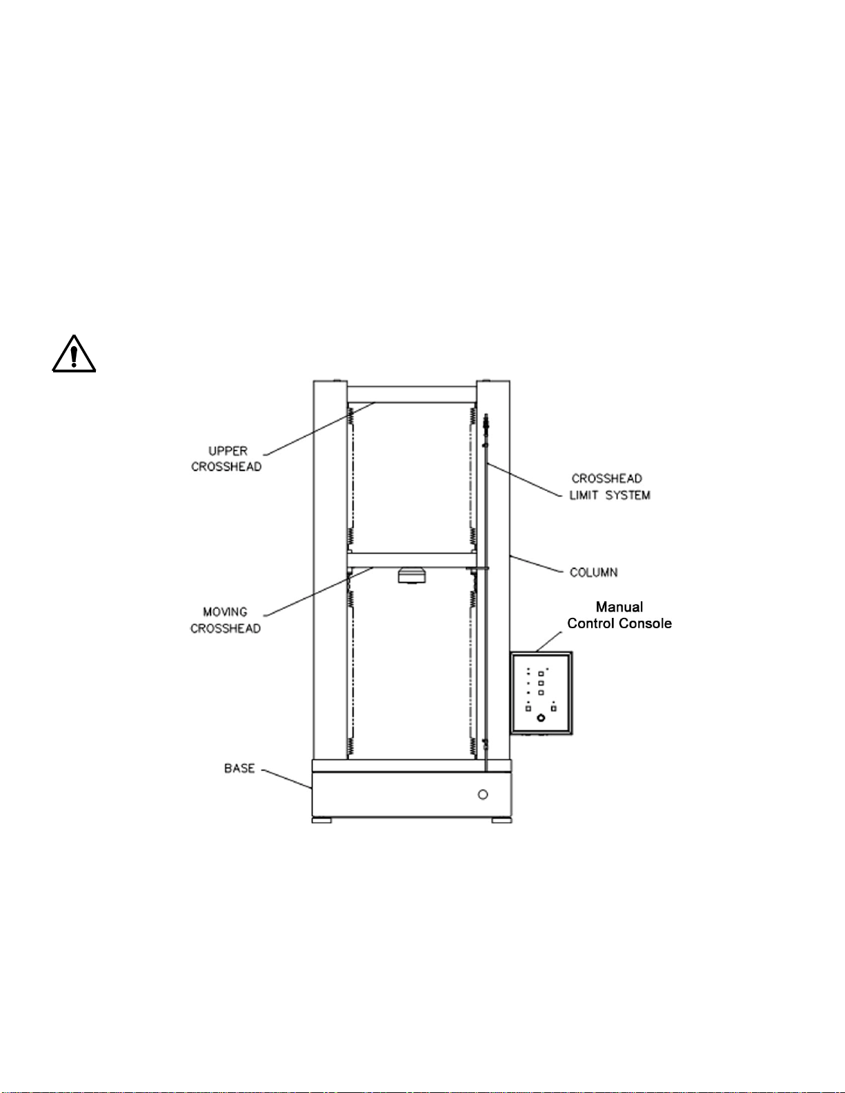
B. Load Frame ...............................................................................................................................................................................8
C. Personal Computer ...................................................................................................................................................................9
D. TestVue®Software ...................................................................................................................................................................9
E. Sequence of Operation .............................................................................................................................................................9
Section 3. Set-Up & Installation.....................................................................................................................................................10
General....................................................................................................................................................................................................10
Unpacking UTM Equipment.....................................................................................................................................................................10
Connecting Equipment ............................................................................................................................................................................10
Software Installation ................................................................................................................................................................................11
Updating Software ...................................................................................................................................................................................12
Attach Accessory Equipment...................................................................................................................................................................12
Accessing TestVue®...............................................................................................................................................................................12
Setting Hardware Parameters .................................................................................................................................................................13
Channel Set-up ..................................................................................................................................................................................13
Setting Software Preferences..................................................................................................................................................................20
Creating Graphs ......................................................................................................................................................................................21
Creating Reports .....................................................................................................................................................................................21
Pre-Set Information .................................................................................................................................................................................21
Options ....................................................................................................................................................................................................21
User Definition .........................................................................................................................................................................................22
Section 4. Controls ........................................................................................................................................................................24
Manual Controls ......................................................................................................................................................................................24
Computer Control Functions....................................................................................................................................................................25
Section 5. Operation......................................................................................................................................................................26
General....................................................................................................................................................................................................26
Creating a Test ........................................................................................................................................................................................26
Viewing Test Specifications.....................................................................................................................................................................32
Adding a Test Description to an Existing Test.........................................................................................................................................32
Positioning the Specimen ........................................................................................................................................................................33
Running a Test ........................................................................................................................................................................................33
Manual Control...................................................................................................................................................................................39
Section 6. Obtaining Results .........................................................................................................................................................41
General....................................................................................................................................................................................................41
Generating a Report ................................................................................................................................................................................41
Printing a Report......................................................................................................................................................................................42
Creating a Report ....................................................................................................................................................................................42
Opening a Report in Microsoft Word .......................................................................................................................................................45
Generating a Graph.................................................................................................................................................................................45
Creating a Graph .....................................................................................................................................................................................47
Zooming In On a Graph...........................................................................................................................................................................48
Exporting Data to ASCII File....................................................................................................................................................................48
Section 7. Maintenance .................................................................................................................................................................51
Maintenance ............................................................................................................................................................................................51

Preface
Unpacking
Retain all cartons and packing materials until the unit is operated and found to be in good condition. If
damage has occurred from shipping, notify Applied Test Systems and the carrier immediately. If it is
necessary to file a claim, retain the packing materials for inspection by the carrier.
Warranty
All ATS, Inc. equipment is shipped with a warranty. Units have a warranty against defective parts and
workmanship for one full year from date of shipment. See the back page of this manual for details.
After-sale Support
If you have any questions concerning the operation of your unit, contact our Service Department. Before
calling, please obtain the serial number from the label on the equipment. The label is shown below.
Serial number__________________________________

Section 1. Safety
All Applied Test Systems Inc. equipment is designed to be operated with the highest level of safety. To
maintain the safe operation of this tester, ATS endevours to educate the operator about safety issues
surrounding certain parts of the tester. These safety issues are addressed through the use of labeling on the
equipment. The following labels may appear on your unit:
Burn Hazard
Hot Surface
Electrical Shock/
Electrocution
Hand Crush
Force From Above
Protective Earth
(Ground)
European Directive CE Mark
General
Danger
No Access For Unauthorized Persons
Read Operator’s Manual
For Owners, Operators, and Maintenance Staff
Read and understand all instructions and safety precautions listed in this manual before installing or operating
your unit. If you have any questions regarding operation of the unit or instructions in this manual, contact our
Service Department.

6
In addition to the safety warnings listed below, warnings are posted throughout the manual. Read and follow
these important instructions. Failure to observe these instructions can result in permanent damage to the
unit, significant property damage, personal injury or death.
Warnings
The following statements are warning statements. Unlike caution statements, warning statements alert the
operator to conditions that may injure personnel. Operators must be aware of these conditions in order to
prevent injuries that may occur while operating this equipment.
Thoroughly understand the safety features and operation of the equipment. This manual will
provide operators with safety concerns and general procedures. Be familiar with correct operating
principals and use good judgment. Also refer to the appropriate manuals for system component
safety instruction manuals.
Do not put your arms or head above or below the moving crosshead. Be aware that hazards
may occur beyond the immediate testing area.
If necessary, stop test operation. In case of an emergency, use the emergency stop button on the
Universal Testing Machine base in order to abort test operation.
Set the limit switches prior to test operation. The limit switches prevent the moving crosshead
from exceeding the pre-set range. Set the limit switches just above and below the ranges set for the
moving crosshead.
Use the appropriate protective equipment when operating the 1600 Universal Test Machine
with accessory equipment. Oftentimes the materials testing is conducted using high temperature
ovens and furnaces. Refer to individual operating manuals for further safety instructions.
Use the software's safety features. Set conditions that cause the test to be aborted if the limits are
surpassed.
Use a protective shield to avoid injury caused by test specimen failure. When performing
materials testing, the force of moving parts may cause the specimen to break and possibly injure
nearby operators. Because materials testing specimens vary so much, it is the responsibility of the
owner and user of the UTM to operate it safely.
Perform maintenance procedures safely. Disconnect power before performing maintenance
procedures.
Cautions
The following statements are caution statements. These statements alert the operator to conditions that may
damage equipment. Operators must be aware of these conditions in order to ensure safe operation of this
equipment.
Use caution when moving the UTM. In order to prevent damage to the UTM, only lift the load frame
by the housing base or by the moving crosshead. Never lift the load frame by the fixed crosshead.

Section 2. System Overview
General Description
The ATS 1600 Series Universal Test Machine (UTM) is designed to provide a versatile, fully integrated,
modular testing system (figure 1). The system consists of a load frame, a personal computer, the necessary
hardware, and TestVue®, ATS’s Window’s based test system software. This system has the following
capabilities:
Performing compressive, tensile, and cyclic tests
Acquiring multi-point data during tests (such as time, displacement, load, strain, and
auxiliary)
Storing batch and specimen tests
Analyzing and summarizing test results
Presenting test results on-screen or on paper
Rapidly selecting and converting between units of measurement
A. Specifications
The load capacity of the UTM depends on the model:
Model 1601 1,125 pound tabletop model (5.0 kN)
Model 1605 5,620 pound tabletop model (25 kN)
Model 1610-TT 11,250 pound tabletop model (50 kN)
Model 1620 22,500 pound floor model (100 kN)
Model 1630 33,720 pound floor model (150 kN)
Model 1660 67,400 pound floor model (300 kN)
The following minimum computer requirements must be met in order to run ATS's TestVue®software.
-Operating System: Windows 9X or better
-Standard PC or Laptop (no computer cards associated with this system)
-Serial Port or USB Port
Specifications subject to change without notice

B. Load Frame
The 1600 Series UTM Load Frame is constructed of a base, columns, an upper crosshead, and a moving
crosshead. Other essential parts include the manual control console and the crosshead limit system.
The UTM base houses an electronically controlled, variable speed motor and low-inertia drive system capable
of a wide speed bandwidth. A zero backlash ball screw drive system operates the moving crosshead, which
can be equipped with various testing accessories.
A manual control console is located on the side of the load frame for manual positioning of the moving
crosshead.
A crosshead limit system is provided with both fixed and user-adjustable stops. The fixed stops are factory
pre-set to prevent damaging crosshead over-travel conditions. This crosshead limit system provides a means
for the user to set custom travel limits on the crosshead based on specific test requirements.
CAUTION: Before operating, set the crosshead limits in order to prevent load cell damage.
Figure 1, Series 1600 Universal Testing Machine (UTM)

9
C. Personal Computer
The 1600 Series UTM functions are controlled by Personal Computer (PC) operating in a Windows®-based
environment. During testing, the computer controls all UTM functions and collects the data such as load,
speed and displacement information, as defined by the user. When tests are not being performed, the
computer permits the user to control the load frame functions using the PC keyboard, mouse or functions on
the control console, located on the UTM frame.
D. TestVue®Software
TestVue®is a Windows®-based software program that allows the operator to easily control the UTM system.
The software provides drop-down menus, radio-button selections, and data entry text boxes for easy update
and access to information.
The software is designed to run on a standard PC/Laptop computer connected to the UTM. During operation,
the computer communicates with the UTM to start/stop testing, monitor test progress and provide data
collection and analysis. The software is organized, so all information required to conduct particular tests is
stored in the personal computer. This design allows software enhancements or new releases to be easily
added to existing UTM's without the need for hardware additions or modifications.
TestVue®is capable of controlling all aspects of the UTM motion and testing. Specifically, the functions
include those listed below:
Crosshead Control / Motion
Test Control of UTM
Test parameter setup and control
Data acquisition and storage
Test analysis and reporting
E. Sequence of Operation
Below is a description of TestVue's®operational steps. A more detailed description is found in the following
sections of this manual.
Figure 2, Sequence of Operation

Section 3. Set-Up & Installation
General
The purpose of this section is to give directions for initial equipment installation and setup.
These directions include how to unpack and position the Universal Test Machine (UTM)
and how to setup the software before performing tests.
Unpacking UTM Equipment
To unpack and prepare the UTM for operation, complete the following steps.
1. Remove the UTM and the computer from the crate.
2. Place the UTM load frame on the floor or a sturdy table, depending on the model type.
CAUTION: In order to prevent damage to the UTM, only lift the load frame by the
housing base or by the moving crosshead. Never lift the load frame by the fixed
crosshead.
CAUTION: If a forklift is used to move the UTM, make sure the forks are far
enough under the base to support it on both sides. If there is not adequate
support, the load frame may tip, or the components within the base may be
damaged.
3. Place the computer system on a work surface near the load frame.
4. Inspect the system for damage during shipment.
NOTE: If damage is found or suspected, notify the shipping company and contact
the ATS Service Department immediately.
Connecting Equipment
The following connection cables are shipped with the 1600 CC UTM. Use them for connecting the
equipment.
Main power cable
Load cell cable
Communication cable
Manual control cable
NOTE: Make sure the cables are undamaged and free of kinks.
1. Connect the main power cable from the bottom right (back) of the UTM base unit to the power supply.
CAUTION: Make sure the appropriate AC power connections are available to the load frame, the
control unit, and the PC. The load frame and computer must be properly grounded. Make
connections to a surge suppressor or a similar line-conditioning device in order to protect the internal
circuitry of both the computer and the load frame.
2. Connect the load cell cable from the back of the load cell, through the clamp located on the moving
crosshead, and into the appropriate connection under the manual control console.

11
3. Connect the communication cable on the bottom left of the UTM base to the computer.
4. Connect the manual control cable on the bottom left of the UTM base and the bottom of the manual control
station.
CAUTION: Prevent power loss to the unit by protecting cables from damage.
5. When connecting additional equipment, refer to the manufacturer's literature for details.
Figure 3, UTM Connections, Rear of UTM
Software Installation
Unless you are providing your own computer equipment, the TestVue®software is already installed on your
computer. In order to install TestVue®, refer to the procedure below.
CAUTION: Only perform the software installation procedures if you supply your own
computer. If the computer is shipped from ATS, installation is not necessary.
NOTE: Before installing TestVue®on your hard drive, be sure your computer system meets
the required specifications given in this manual.
Install the software on a computer with a hard disk containing at least 100 megabytes of free space. Use the
appropriate drive for the CD ROM.
1. Turn the power on to the PC and wait for the computer to complete its start-up sequence.
2. Place the ATS TestVue®Software Disk in drive the CD ROM of the computer.
3. Initiate installation as prompted on the screen.

12
4. Another method is to locate the SETUP.EXE file in the directory found on the TestVue software CD. This
action will initiate the software installation progress.
5. Follow the instructions and prompts on the screen.
Updating Software
Periodically, TestVue®is updated. When an updated copy of the software is received in the mail, follow the
procedure previously described.
CAUTION: Prior to re-installing TestVue software or installing an updated version, make sure to
backup all the files located in the TestVue32 directory. Refer to the attached diagram. Failure to
backup these files will result in lost data that cannot be retrieved.
Attach Accessory Equipment
A wide range of accessory equipment such as grips, fixtures, and laboratory ovens can be used with the 1600
CC UTM. Attach this equipment before testing. Refer to the appropriate equipment manuals. For more
information about accessory equipment available for your UTM, contact your ATS Sales Representative.
Accessing TestVue®
1. Turn the UTM and the computer power on. Enter the Windows®software, and double-click on the
TestVue®icon.
2. Follow prompt for centering Jog Pot.
3. The Login window appears as shown below. Enter your user name and password. For initial use login as
"New User." The corresponding password is "password." This initial user has system administrator
privileges.] The purpose of this password feature is to control user access to testing.
Figure 4, Login Screen

Setting Hardware Parameters
In order to properly control and monitor UTM tests, TestVue®must have an accurate list of analog
components that are used on the load frame. These parameters must be defined before conducting tests.
Normally, the machine is set up with the correct parameters before leaving the factory, but changes to the
components may be done after the UTM is in service. The TestVue®Setup Menu provides an easy way for
the user to specify the transducer values that will be used during testing.
Channel Set-up
Channel set-up must be completed before any tests are performed. All elements of the system have specific
characteristics. The software must recognize these values to be able to work with them.
NOTE: Complete the following setup procedure below (for each transducer) only if the transducers
being used are not ATS-modified. Complete this procedure for each transducer.
NOTE: If the UTM transducers are supplied by ATS, they will contain information within the
transducer cable that will automatically perform this setup when the transducers are connected. In
these cases, no extra setup for the Analog Input channels is required.
NOTE: If supplying a load cell, a new EPROM will need installed or a prompt will advise there is no
calibration record for this load cell. Until EPROM is installed, click ok to bypass. Refer to diagram
below.
1. In order to configure the analog input, perform the steps below.
a. Select Setup from the main menu.
b. Select Channels from the vertical menu.
c. Select Analog Input from the menu, and the Analog Input Configuration window will appear as
shown below.
Figure 5, Setup Channels

14
Figure 6, Analog Input Configuration Screen
d. Configure each channel for the requirements of the device connected to it. Four channels are
available. Two are standard and two are optional. Each has a pull down list that includes common
devices that may be configured. Enter or select the following. (If a channel is empty, specify None.)
Analog Transducer Information - Select the type of equipment connected to this channel.
Enter the serial number of the equipment type in the appropriate box.
Electrical Characteristics - Enter the maximum excitation amount, values for the sensitivity,
zero offset, and full-scale output. Refer to Specifications, if necessary.
Full Scale and Units - Enter the Full-Scale Value and Unit of Measurement for each
channel.
e. Select OK to exit this window.
2. Scale the analog output by assigning a channel to communicate with an external device.
NOTE: The hardware required for analog output ability is optional. If this hardware is provided, the
analog output can be accessed from cables attached to the back of the computer, next to the
communications cable.
a. Select Setup from the horizontal menu.
b. Select Channels from the vertical menu. The channel type may already be determined by the
device type chosen.
c. Select Analog Output from the menu, and the Analog Output Scaling window will appear.

15
Figure 7, Analog Output Scaling
d. Enter or select the following from the pull-down menu.
Source Channel - Select a channel from the pull-down menu. ("Ain" is analog input.) The
source channel will communicate with an external device.
Scale - Select a voltage scale from the pull-down menu.
Slope - Enter a slope value. The slope is the selected units per volt (for example, KN/v). If
zero is selected, no analog output will be generated.
Offset - Enter an offset value.
e. Select OK to exit the window.
3. In order to configure the serial channel, establish operating parameters for communication with serial
devices connected to the system.
a. Select Setup from the main menu.
b. Select Channels from the vertical menu.
c. Select Serial, and the Serial Channel Configuration window will appear as shown below.

16
Figure 8, Serial Channel Configuration
d. Enter or select the following from the Serial Channel Configuration window:
Serial Transducer Information:
Device Type - Choose the device type from the pull-down menu.
Channel Type - Choose the channel type from the pull-down menu.
COM Port - Choose the port number from the pull-down menu.
Configure Comm - Select this button and the window appears as shown below. Select the
appropriate information.
Figure 9, Configure Serial Port

17
Generic - Select this pushbutton if the generic Device Type was chosen previously. The
window will appear as shown below. Enter the transducer type, communication format,
measurement scaling, and plotting limits.
Figure 10, Generic Serial Transducer Configurations
e. Select OK to exit the window.
4. Configure the virtual channels.
NOTE: Virtual channels are channels that may be assigned by the user to combine one or two of the
normal channels and a math function.
Results from virtual channels may be treated as results from any other device and included in graphs or
reports. They cannot be used as a control channel for running tests, such as load, strain, or displacement
control. The virtual channels may also be selected as elements of the run time graphs that appear during a
test. Channels 9 - 11 are available as virtual channels.
a. Select Setup from the horizontal menu.
b. Select Channels from the vertical menu.
c. Select Virtual. The Virtual Channel Configuration window will appear as shown below.

18
Figure 11, Virtual Channel Configuration
d. Enter or select the following:
Virtual Transducer Information:
Status - Select Enabled in the pull-down menu.
Name - Enter a name for the transducer. This name will appear on any graphs
created with this channel, and the name will appear on the .CSC files and Excel
reports.
Units - Enter the type of units. This unit designation is just text. It will not alter the
numerical value of the data or the results of any calculations.
Configure - Select this button to establish device parameters.
e. Enter or select the following:
Variables - In order to assign the "normal" channel(s) such as load or strain to virtual
channel(s) A and/or B, K (Constant) values may be added.

19
Figure 12, Virtual Channel Information
Function - Select a function from the pull-down menu. The purpose of the Function selection
is to assign the calculation.
f. Select OK to exit the Virtual Channel Configuration window.
g. Select OK to exit the Virtual Channel Information window.
5. Map the control channels.
NOTE: Control channels are channels that provide test control.
Figure 13, Control Channel Mapping
a. Select Setup from the horizontal menu.
b. Select Channels from the vertical menu.
c. Select Control Channel Mapping, and the window will appear as shown below.

20
d. Enter or select the method of control.
Load - Select the channel pertaining to the load transducer.
Strain - Select the channel pertaining to the strain transducer.
Displacement - Select the crosshead or channel pertaining to a displacement transducer.
Comment - Comments may be entered for use on this screen only. These comments will not
appear on other screens.
e. Select OK to exit the window.
After the system is configured, the system setup is saved. If changes are made to the hardware
configuration, revise the software setup accordingly.
Setting Software Preferences
Establish preferences for software operation. These preferences allow the user to select options such as
report headings, ability to run the test in DEMO mode, require passwords, and establish new paths for saving
test information, among other options. Refer to the figure below.
1. Select Setup from the horizontal menu.
2. Select Preferences, and the window below will appear.
Figure 14, Preferences
3. Enter or select the following.
Report Header Defaults - Enter a name for Header 1 and/or Header 2. These headers appear on
reports that are generated within TestVue®.
System Options - Select the boxes beside the available options in order to modify access to the
software or program functions.
This manual suits for next models
6
Table of contents
Other ATS Test Equipment manuals