ATTACK SOLARTHERM HSA 200 User manual

SOLAR TECHNIQUE
ATTACK
®
SOLARTHERM HSA 200
W W W . A T T A C K . S K
PARALLEL MOUNTING
BRACKETS ON THE ROOF

3
Content
Safety warnings ...................................................................................................................... 4
Shipping instructions .............................................................................................................. 5
Installation instructions .......................................................................................................... 6
Tools Overview ....................................................................................................................... 7
Material Overview .................................................................................................................. 8
Recommended mounting points ............................................................................................10
Parallel mounting brackets on the roof .................................................................................. 11
Specifications ....................................................................................................................... 17
Recommendations for service ............................................................................................... 18
Warranty ............................................................................................................................... 20
4
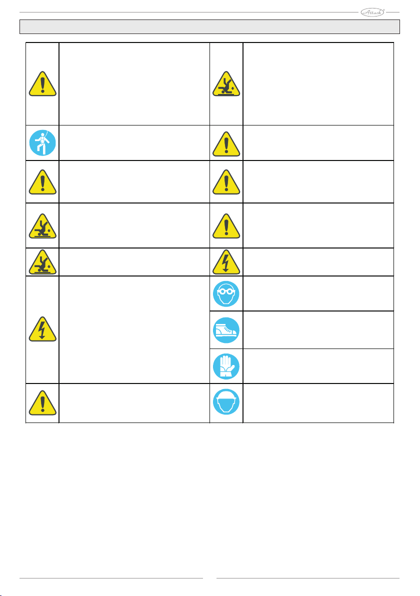
Safety warnings
In the case of mounting on the roof - before the work –
it is essential to install compliant independent
protection against falling or catching device according
to DIN 18338 on roofing work on the roof and sealing
work on roofs and in accordance with DIN 18451 for
work on scaffolding safety net! Regulation on the
protection of workers in construction BGBl 340/1994 §
7-10! It is absolutely necessary to keep other
regulations in the country!
Safety harness must be preferably nailed above the
user. Fix safety harness only to eventually building
components or points that have sufficient capacity!
Only prescribed heat transfer medium!
If there are no safeguards against falling or catching
device-independent entities due to the technical
reasons, it is necessary to use a safety harness!
Do not use damaged ladders, for example cracked
beams with a wooden ladder rungs, bent and broken
metal ladders. Do not repair brittle beams, side walls
and walls of wooden ladders!
Use only safety harnesses, which are identified and
tested by authorized testing laboratory (safety or
webbing, connecting cords / belts, shock absorbers,
shortening ropes).
Place the strap-on ladders safely. Be careful when
attaching the right angle (68 ° - 75 °). Strap ladders
are secured against slipping, overturning, sliding and
running, for example advanced bases, bases ladder
adapted substrate hinges.
If there are no protection devices against falling or
catching independent on people, without the use of
safety harnesses there is danger of falling from great
heights and thus of severe or fatal injuries!
Ladders rest only to the secure anchors. In the field of
transport ensure ladders by closures.
When using ladders, there is danger of falls caused
by slipping, fall or flip over the ladder! Contact with loose electrical lines can be fatal.
In the case of drilling and handling collectors wear
goggles!
During installation, wear safety boots!
When mounting and handling collectors, wear gloves
providing protection against cuts!
The manufacturer hereby undertakes to take back
products marked with the ecological brand and
materials they contain, to deliver for further
processing. Only prescribed heat transfer medium can
be used!
During installation, wear a helmet!
Near unattached electrical lines, with which contact is
possible, work only if state was secured when they
are not under voltage and this condition is ensured
during the entire period of work, electrically conductive
parts are protected by fencing or covering them, and
there is no reduction of safety distance.
Radius of voltage
1 m ...........................1000 V voltage
2 m ...........................voltage from 1000 to 11000 V
3 m ...........................voltage from 11000 to 22000 V
4 m ...........................voltage from 22000 to 38000 V
> 5 m in the case of unknown voltage

5
Shipping instructions
Do not lift the collector for the connector or a threaded screw connections!Attention:

6
Installation instructions
General warnings and warnings of carriage
The mounting system is only suitable for roofs with tiled roofing. Installation can be performed only by specialized
personnel. All work in this guide apply only to such specialized personnel. When installing in principle be used the
supplied material. Before installation and operation of solar collectors with a view to inform the applicable local rules
and regulations. When transporting the collector is advised to use the conveyor belt. The collector may not be lifted for
a connection or threaded screw connections. Avoid shock and mechanical impact on the collector, especially for solar
glass, rear wall and pipe connections.
Statics – roof with tiled roofing
Installation may be done only on flat roofs or bearing constructures with sufficient capacity. Before mounting the
collectors should definitely check the static load capacity of the roof or bearing constructure, in each case the call
should be static, to examine local and regional features. In doing so, it is necessary to pay particular attention to the
quality (wood) of bearing constructure - strength bolting consolidating assembly plant collectors. Inspection of the
structures collectors at their place of installation according to DIN 1055, part 4 and 5 or under the law of the country is
necessary especially in areas with high snow precipitation (note: 1 m3of snow dust ~ 60 kg / 1 m3of wet snow ~ 200 kg)
or in areas with strong winds. It should be taken of all the specific location of installation of equipment (warm Alpine
wind, the effects of flow turbulence wind, etc.) that could result in an increased burden on the device. When selecting
the installation site must be ensured in order for not to exceed the maximum loads or forces acting due to wind or snow
precipitation. In principle, the collector arrays have to be installed so that if any snow accumulation in the catchment
grid (or accumulated due to the specific situation of the installation) can not reach the collector. Collectors may not be
installed on the roof edge (it should be observed marginal zone E/10 on flat roofs according to EN 1991, at least 1 m).
The upper edge of the collector shall not protrude above the roof.
Installation of a solar collector field represents interference in the (existing) roof. Roofing such as tiles,
shingles and slate, especially furnished and habitable attic or roofs with insufficient slope (with respect to their
roofing) requires the implementation of construction protections (for example support construction) as a hedge
against the ingress of water due to wind pressure and drifting snow.
Protection against lightning / settlement potential building
In accordance with current standards for protection against lightning ÖVE / ÖNORM EN 62305 part 1-4, the collector
array may not connect the lightning conductor buildings. It is necessary to keep a safety distance min. 1 m from
possible neighboring conductive object. For mounting on a metal support structure is generally necessary to consult
with a qualified electrician. In order to realize the potential of settlement building by an authorized electrician must
connect metal pipe solar circuit as well as all caps or holders of collectors with the main rail for bonding in accordance
with standard ÖVE / ÖNORM E 8001-1 or standards applicable in the country.
Connections
Collectors must be interconnected, depending on their design screw connections (1 "IG / AG) or by connecting
pipe so that the surfaces of joints sealed. It is necessary to ensure the proper imposition of gaskets. If you are not
connecting elements as scheduled no flexible hoses, it must be ensured in order to have the connecting pipes take
appropriate steps to compensate for thermal expansion due to temperature fluctuations, for example.: Expansion bends
and flexible pipes (see link collectors / operational recommendations). For larger collector fields is necessary to insert
the expansion bends or flexible joints (Attention: need to check the sizing of the pump). When tightening the
connections necessary to follow from the other side (control) or other tick-key, to avoid damage to the absorber.
Inclination angle / general information
The collector is suitable for slope min. 15 ° max. 75 °. Connections collectors and ventilating / air vent openings should
be protected from water penetration and dirt and dust ingress, etc.
Warranty
The warranty arises only use the original means of frost protection from the supplier and properly carried out
installation, commissioning and maintenance. A precondition for entitlement to guarantee the installation of qualified
personnel, without exception, adherence to instructions in the manual.
Attention:
7
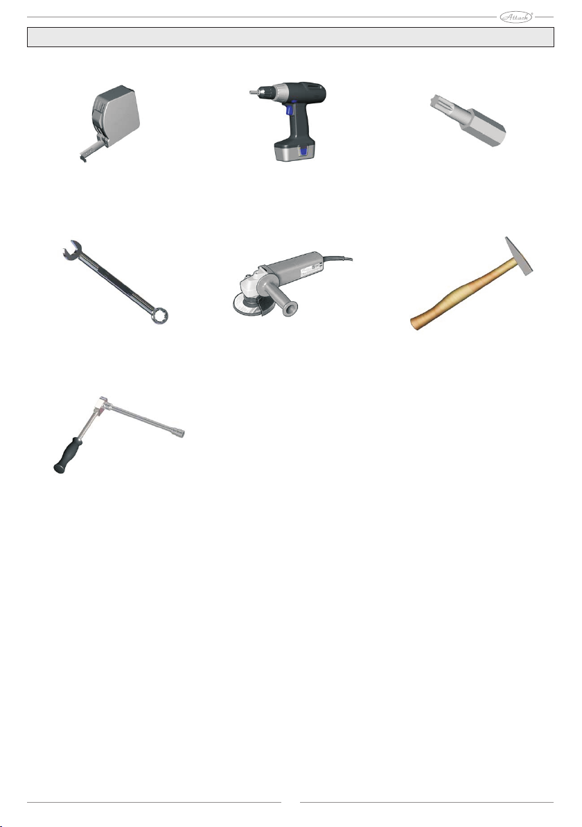
Tools Overview
Hexagonal wrench
Drill Allen handpiece
Angle Grinder
Measuring tape
Hammer
Ratchet with extension
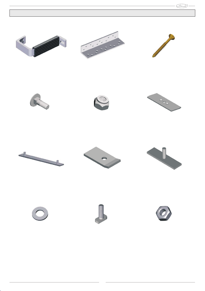
8
Material Overview
Roof Mount Roof mount bracket Screw 6*60
ClampSelf-locking hex nut M8Screw hinges M8*25
Clutch bearing profiles Mounting flange Mounting bracket
Hexagon nut M8T Bolt M8x25
Wascher M8

9
Carrier rail Mounting template Gasket
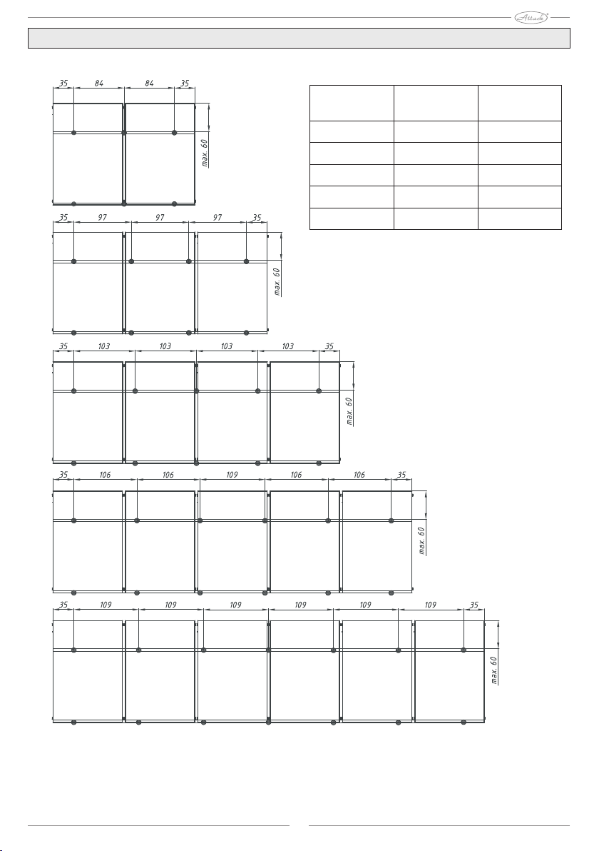
10
Recommended mounting points
Collectors Total length Mounting
points
2
3
4
5
6
239 cm
361 cm
482 cm
603 cm
724 cm
6
8
10
12
14
In areas with large snowfall or high wind areas, it is
necessary to schedule additional fasteners! (DIN 1055
follow eventually. Of force in the country).

11
Parallel mounting brackets on the roof
General Warning: Points 8 - 11, 16 and 17 are needed only for installation of more than two collectors!
1 )
2 )
3 )
4 )
1: The vertical dimension of the collector -> A = 125 - 155 cm
2: Focus attachment points (see recommendation from previous
page), remove the slate / roofing
Generally: for one collector is needed one Fasteners.
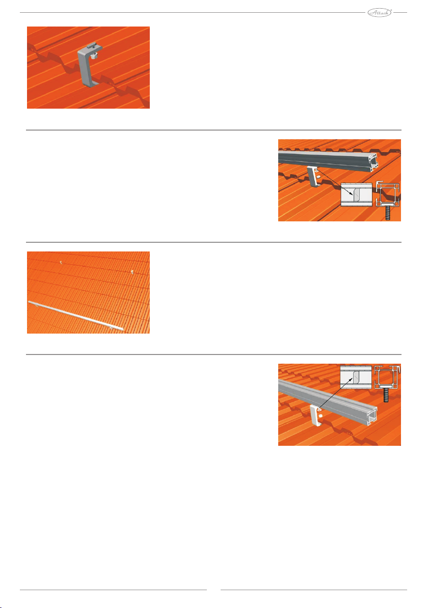
3: Connect the roof mount bracket with umbrella holder, flatten
them and fasten with screws 6 * 60th
4: Place the slate / roofing, if necessary, adjust it.
12
5 )
6a )
6b )
7a )
5: The roof mount insert screws with a flat head and tighten them
first hand only.
Order: screw with a flat head - roof mount - washer – nut
6: Install the lower bearing rail (6a, 6b)
Order: Bearing rail – screw with a flat head - roof mount - washer
- nut
7: Install the upper bearing rail (7a, 7b)
Order: Bearing rail – screw with a flat head - roof mount - washer
- nut

13
7b )
8 )
9 )
10 )
Attention: The upper and lower bearing rail must fit together
perfectly straight and parallel!
8: Install additional mounting points under 1 – 4.
9: Push and pull terminal extension until the middle of the inner
matrix of the bearing rails (top and bottom).
Order: Bearing rail - terminal extension - washer – nut
10: Put another bearing rail (top and bottom) and attach it to an
extension terminal.
Order: Bearing rail - terminal extension - washer – nut

14
11a )
11b )
12a )
12 b )
11: Attach the bearing rails (top and bottom) with roof bars
or terminal extension.
Order: Bearing rail – screw with a flat head - roof mount
washer – nut
12: Hang the first collector to the lower bearing rail and
straighten it (12a + 12b!).
The distance between the collector and the end of the
bearing rails = 45 mm. A dimension = dimension B!
Warning:

15
13 )
14a )
14b )
15 )
13: Place the clamp on the upper bearing rail and tighten them
first hand only.
Order: Top bearing rail – screw with a flat head - washer - clamp
- washer – nut
14: Hang the second collector. (Dimension A = dimension B in
FIG. 12b). Please use the mounting template (14b).
15: Turn the clip 90 degrees and firmly tighten with a long socket
wrench.

16
16 )
17 )
18 )
19 )
16: For each affecting bearing rails slide and place the mounting
part extending into the upper bearing rail.
17: Install additional terminal / other collectors, according to
point 12 – 16.
18: Replace the fixing unit to the left and right upper end of the
collector box.
Order: Bearing rail – screw with a flat head - fitting parts -
washer – nut
19: Connect the collectors with and torque.

17
1221
83
117
70
1730
1170
Specifications
Gross area
Net area
Surface hole
Weight
Capacity
Maximum operating
pressure
m2
m2
m2
2,02
1,84
1,91
kg
l
bar
31
1,4
10

18
Recommendations for service
Rinsing and performance
For security reasons, the device must perform when collectors are not exposed to sunlight, where it is
necessary to cover collectors. Especially in areas where there is danger of frost, facility has to be filled
with a mixture of water containing up to 40% of frost protection. To protect the materials from excessive
heat load device is to be filled and placed in service as soon as possible, but not after 4 weeks. If this is not
possible before putting into operation is necessary to replace gaskets to prevent leaks.
Pre-mixed composition frost protection is necessary before filling in device mixed with
water!
Recommended means of frost protection for flat plate collectors: TYFOCOR-L
40% of the means of frost protection (60% / water) - frost point of - 22 ° C / FREEZING POINT: - 26 ° C
50% of the means of frost protection (50% / water) - frost point of - 32 ° C / FREEZING POINT: - 44 ° C
It is possible that filled collectors can no longer be completely removed. For this reason the threat of frost
collectors may also be carried out in order to perform pressure and functional testing only a mixture of
water and frost protection. Alternatively, you can also do a pressure test using compressed air and spray
the leak search jobs.
Mounting the sensor
The temperature sensor should be mounted in the outlet collector box located next to the sensor housing.
In order to ensure optimal contact, the gap between the housing and a sensor with adequate heat-
conductive paste. When installing the sensor may be used only material with sufficient resistance to high
temperatures (250 ° C) (body sensor, contact paste, wire, sealants, insulation).
Operating pressure
Max operating pressure is 10 bar.
Ventilation
Equipment must be vented:
- when it is placed in service (after filling),
- 4 weeks after commissioning,
- if necessary, for example in case of disturbances.
Danger of scalding hot steam or heat transfer fluid!
The ventilation valve handle only when the heat transfer fluid temperature < 60 °. In the discharge device
may be hot collectors! Cover Collectors and let out device preferably in the morning.
Control of heat transfer fluid
Every two years, it is necessary to check the frost protection and heat transfer medium pH.
- Frost protection, check with measuring means frost protection and if necessary replace or add the means.
Required value of protection is approx. - 25 ° C to - 30 ° C or by weather conditions.
- Check the pH with indicator sticks pH (nominal value is approx. PH 7.5):
In case of fall below a threshold pH L 7 replace heat transfer medium.
Maintenance collector
Collector or collector array must be visually inspected every year - if they are not damaged, the seal,
pollution, etc. Other recommendations for operation and maintenance can be found in the general
instructions for commissioning and maintenance / rules from the supplier.
Attention:
Warning:
19
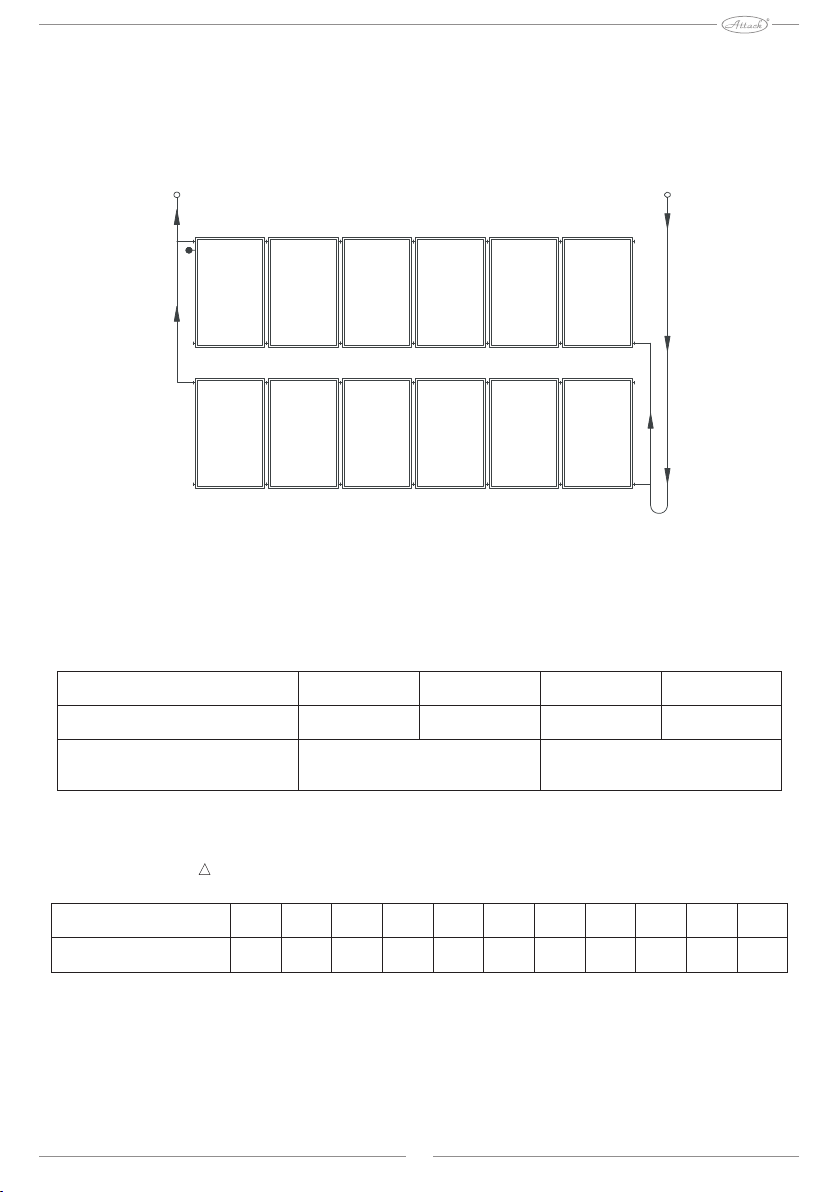
Link collector
A possible link can be seen in the attached sketch. Based on the structural characteristics of the
situation, however, may be different in practice. If the collector field consists of more than 6
collectors (vertically aligned) or 4 collectors (arranged horizontally) in the series, it is necessary to
plan appropriate measures to compensate for thermal expansion due to temperature fluctuations
(expansion bends or flexible pipe) or a field to be multiple times in parallel run.
Output Reverse
Flow rate
In order to achieve good performance collector, should be the size of the field around the collector about
25 m² to choose a specific flow rate 30 l / m² h.
Pipe cross-section
Table sizing, specific flow rate 30 l / m2h
The size of the collector field
Diameter pipe / copper
Diameter pipe / corrugated
stainless steel pipes
pribl. 5
10 - 12
DN16
pribl. 7,5
15
pribl. 12,5
18
DN20
pribl. 25
22
The pressure loss in one collector in the case of a mixture of antifreeze agent / water (40% / 60%)
where the heat transferfluid temperature 50 ° C.
Pressure loss curve: p = 0,0000106x² + 0,0137580x
Flow rate
Pressure loss
0
0,70
50
1,5
100 150
2,3 3,2
200 250
4,1 5,1
300 350
6,1 7,2
400 450
8,3 9,5
500

20
Warranty
For cases using the device for the purpose for which it is not intended or alterations assembly components
and the consequences resulting from such proceedings are not covered by warranty. All information and
instructions in this guide apply to the current state of development. Please always use the appropriate
assembly instructions supplied with collectors. Photographs of symbols are used as pictograms. They are
based on the potential rate of error in a press, but also due to the need of constant technological changes,
please understand, that we can not assume any liability for the accuracy of the content of the document.
We refer you to the validity of the General Conditions in their amended version. This installation manual
contains its own information, subject to copyright protection. All rights and changes in this assembly
manual are reserved.

ATTACK, s.r.o. – 06/2015
ATTACK, s.r.o.
Dielenská Kružná 5020
038 61 Vrútky
Slovak republic
Tel: +421 43 4003 103
Fax: +421 43 3241 116
E-mail: export@attack.sk
Web: www.attack.sk
Výrobca ATTACK, s.r.o. si vyhradzuje právo technických zmien výrobkov bez predchádzajúceho
upozornenia. • ATTACK, s.r.o. producer reserves the right to change technical parameters and dimensions
of boilers without previous warning. •Der Hersteller ATTACK, s.r.o. behält sich das Recht der technischen
Veräderungen an Produkten ohne eine vorige Warnung. • Изготовитель ATTACK, s.r.o. оставляет за собой
право изменения технических параметров и размеров котла без предыдующего предупреждения.
• Le producteur ATTACK, s.r.o. réserve le droit des modifications techniques sans l‘avertissement
précédent. • Productor ATTACK, s.r.o. reserva el derecho de cambios técnicos sin advertencia anterior.
Table of contents
Popular Solar Panel manuals by other brands


SOLUXTEC
SOLUXTEC PowerSlate Framed Mono Dark Blue Series user manual

Sunload
Sunload Solarclaw user manual

Solglass
Solglass Solartrix 1200-400 Series installation manual

Autarco
Autarco TBJ Series Installation and operation manual

STC
STC Solar SPA Collector Kit installation guide

LONGI
LONGI LR6-60 M Series installation manual