ATV 22X MINITRAX III User manual

INSTRUCTION MANUAL
22X MINITRAX III
DOME CAMERA
Please read this manual thoroughly before use and keep it handy for future reference.

II
CAUTION
EXPLANATION OF GRAPHICAL SYMBOLS
The lightning flash with arrowhead symbol, within an
equilateral triangle, is intended to alert the user to
the presence of uninsulated “dangerous voltage”
within the product’s enclosure that may be of
sufficient magnitude to constitute a risk of electric
shock to persons.
The exclamation point within an equilateral is
intended to alert the user to the presence of
important operating and maintenance (servicing)
instructions in the literature accompanying the
appliance.

III
FCC COMPLIANCE STATEMENT
FCC INFORMATION:
This equipment has been tested and found
to comply with the limits for a Class A digital device, pursuant to
Part 15 of the FCC Rules. These limits are designed to provide
reasonable protection against harmful interference when the
equipment is operated in a commercial environment. This
equipment generates, uses, and can radiate radio frequency energy
and, if not installed and used in accordance with the instruction
manual, may cause harmful interference to radio communications.
Operation of this equipment in a residential area is likely to cause
harmful interference in which case the user will be required to
correct the interference at his own expense.
CAUTION:
Changes or modifications not expressly approved by
the party responsible for compliance could void the user’s authority
to operate the equipment.
This Class A digital apparatus complies with Canadian ICES-003.
Cet appareil numérique de la classe A est conforme à la norme
NMB-003 du Canada.
CE COMPLIANCE STATEMENT
WARNING
This is a Class A product. In a domestic environment this product
may cause radio interference in which case the user may be
required to take adequate measures.

IV
IMPORTANT SAFETY INSTRUCTIONS
1. Read these instructions.
2. Keep these instructions.
3. Heed all warnings.
4. Follow all instructions.
5. Clean only with dry cloth.
6. Do not block any ventilation openings. Install in accordance with the
manufacturer’s instructions.
7. Do not install near any heat sources such as radiators, heat registers,
stoves, or other apparatus (including amplifiers) that produce heat.
8. Do not defeat the safety purpose of the polarized or grounding-type
plug. A polarized plug has two blades with one wider than the other. A
grounding type plug has two blades and a third grounding prong. The
wide blade or the third prong are provided for your safety. If the
provided plug does not fit into your outlet, consult an electrician for
replacement of the obsolete outlet.
9. Protect the power cord from being walked on or pinched particularly at
plugs, convenience receptacles, and the point where they exit from
the apparatus.
10. Only use attachments/accessories specified by the manufacturer.
11. Use only with the cart, stand, tripod, bracket, or table
specified by the manufacturer, or sold with the
apparatus. When a cart is used, use caution when
moving the cart/apparatus combination to avoid injury
from tip-over.
12. Unplug this apparatus during lightning storms or
when unused for long periods of time.
13. Refer all servicing to qualified service personnel. Servicing is required
when the apparatus has been damaged in any way, such as power-
supply cord or plug is damaged, liquid has been moisture, does not
operate normally, or has been dropped.
14. CAUTION – THESE SERVICING INSTRUCTIONS ARE FOR USE
BY QUALIFIED SERVICE PERSONNEL ONLY. TO REDUCE THE
RISK OF ELECTRIC SHOCK DO NOT PERFORM ANY SERVICING
OTHER THAN THAT CONTAINED IN THE OPERATING
INSTRUCTIONS UNLESS YOU QRE QUALIFIED TO DO SO.
15. Use Certified/Listed Class 2 power source only.

V
Table of Contents
Chapter 1 — Introduction...........................................................................................................1
1.1 Features.............................................................................................................................................1
Chapter 2 — Installation and Configuration.........................................................................2
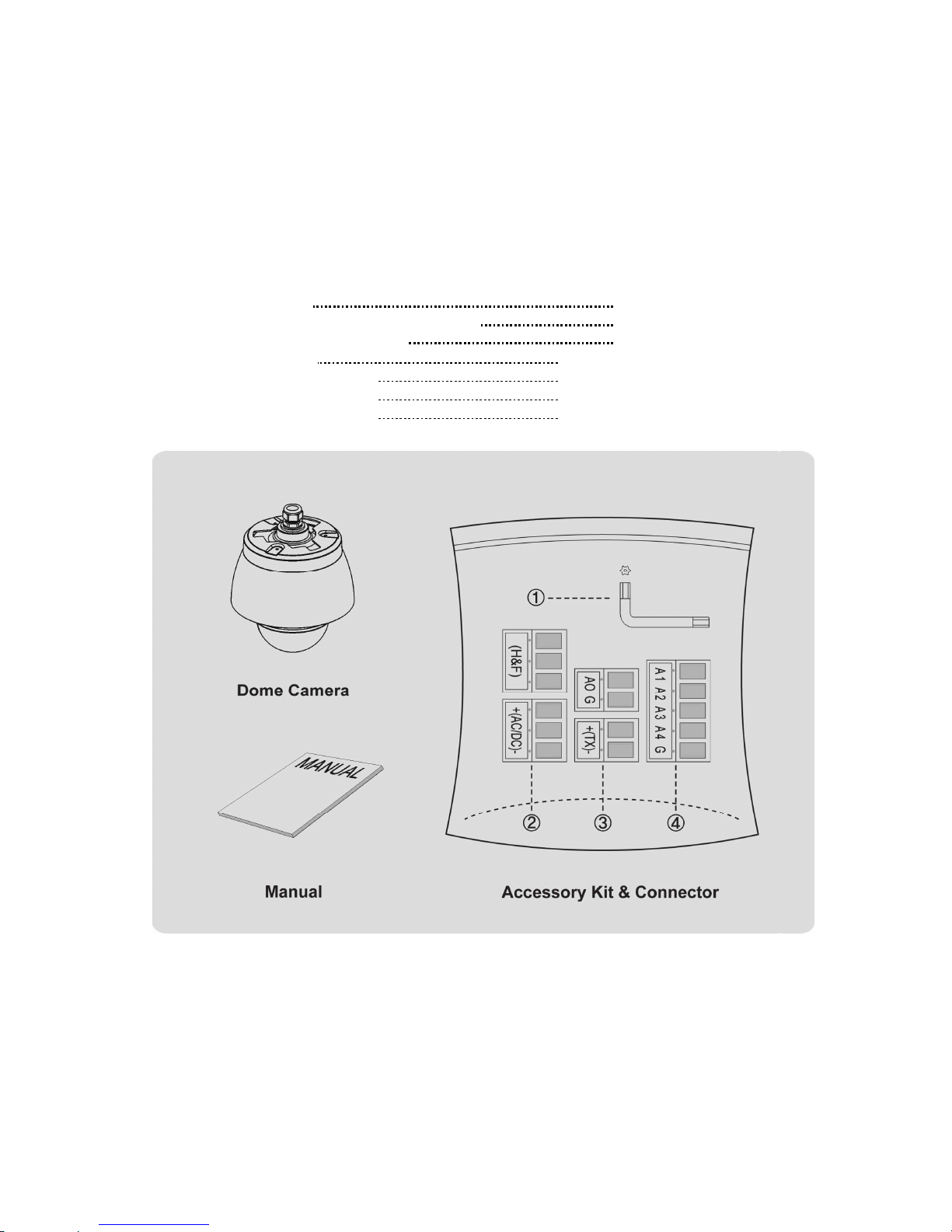
2.1 Package Contents............................................................................................................................2
2.2 Installation.........................................................................................................................................3
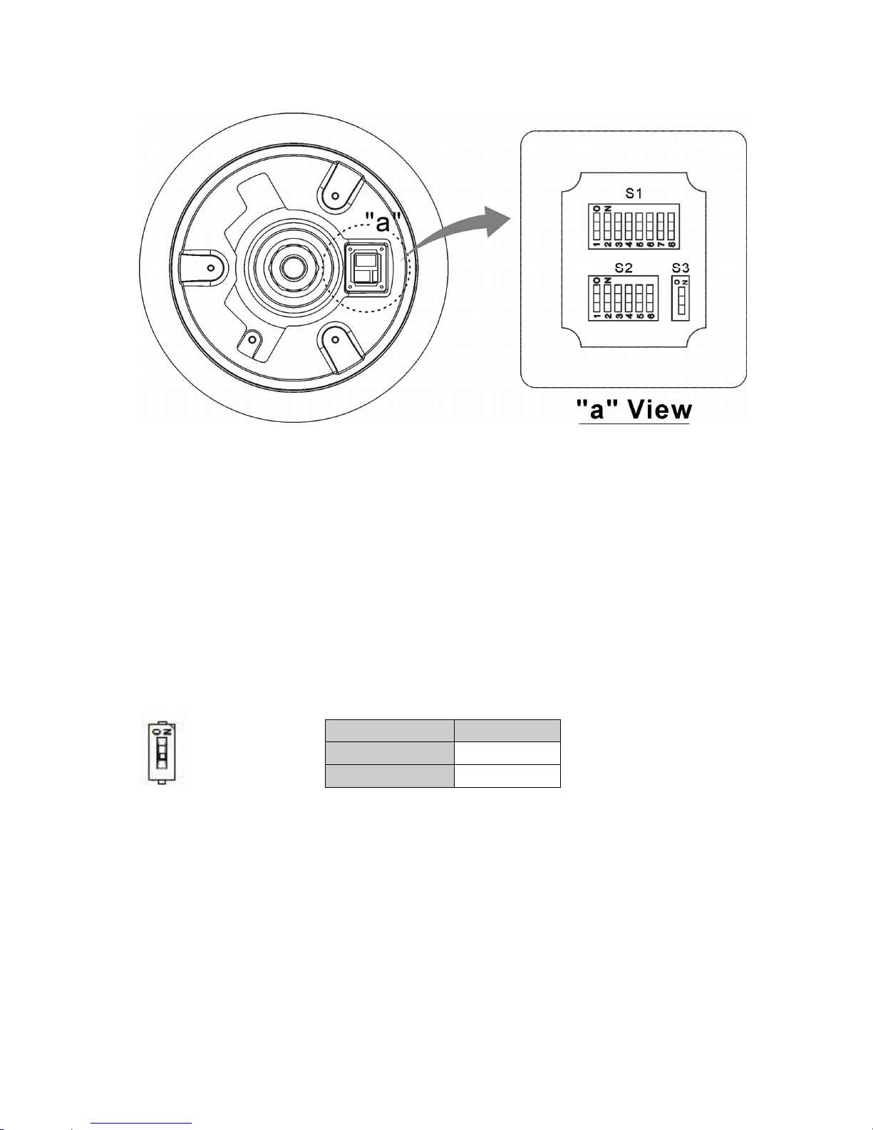
2.3 Basic Configuration of Dome Camera System........................................................................4
2.4 Setting Dome Camera Termination.............................................................................................5
2.5 Setting Dome Camera Address (ID)............................................................................................5
2.6 Setting Dome Camera Protocol and Video.............................................................................12
2.7 Connections....................................................................................................................................12
2.8 Getting Started...............................................................................................................................13
Chapter 3 — Program and Operation...................................................................................14
3.1 Dome Camera Selection..............................................................................................................14
3.2 Accessing the On-Screen Menu Utility....................................................................................14
3.3 How to control the On-Screen Menu Utility............................................................................15
3.4 Auto Scan (Shortcut: SCAN) ......................................................................................................15
3.5 Preset (Shortcut: PRST) ..............................................................................................................17
3.6 Shortcut of Preset Program........................................................................................................19
3.7 Tour (Shortcut: TOUR).................................................................................................................19
3.8 Pattern (Shortcut: PTRN) ............................................................................................................21
3.9 Alarm.................................................................................................................................................22
3.10 Area Title........................................................................................................................................22
3.11 Privacy Zone.................................................................................................................................23
3.12 Camera Menu................................................................................................................................24
3.13 Dome Setup ..................................................................................................................................27
3.14 Function Run................................................................................................................................33
3.15 Factory Setup...............................................................................................................................34
Appendix A — Specifications.................................................................................................35
Appendix B — Troubleshooting.............................................................................................37
Appendix C — Glossary...........................................................................................................37
Appendix D — Short Cut Key .................................................................................................40
Appendix E — Wall Mount.......................................................................................................41
Appendix F — Ceiling Mount..................................................................................................42

1
Chapter 1 — Introduction
1.1 Features
The dome camera and the keyboard controller make up the building blocks for any
surveillance/security system. Using multiple keyboard controllers and multiple dome cameras, no
place is too large for monitoring. Extensible and flexible architecture facilitates remote control
functions for a variety of external switching devices such as multiplexers and DVRs.
•Built-in optical power zoom camera with True Night Shot function
•240 Preset positions with the individual Camera AE setup
•8 Tours consist of Presets, Patterns, Auto Scans and other Tours can be programmed with
over 300 functions and preset locations. While moving, each Preset scan can be watched in
smooth Vector Scan mode.
•16 Auto Scans with the normal, the vector, and the random mode and the endless Auto-Pan
with 13 speed steps
•8 Patterns (up to 200 second) and 8 Privacy Zones
•16 Area Titles
•4 Alarm inputs / 1 Alarm output (5VTTL)
•Variable speed from 0.1°/sec to 380°/sec
Three Variable speed (SLOW, NORMAL, TURBO)
Turbo speed is 380°/sec with Ctrl key pressed.
•Pan/Tilt speed is inversely proportional to the zoom ratio with the option.
•Maximum speed is 380°/sec when Preset command.
•Auto Calibration from 0.1°to 6°(Tilt range is 0°to 180°)
•Programmable user preferences (alarm, preset, title, etc.)
•180°Digital Flip
•Up to 255 selectable camera addresses
•Multi-language Menu Display, Password Confirmation
•Function Run menu using DVR without function key (Pattern, Scan, …)
•Built-in RS-485 receiver driver
•24VAC or 12VDC for Dome
•24VAC for Heater & Fan
•Use Certified/Listed Class 2 power source only.

2
Chapter 2 — Installation and Configuration
2.1 Package Contents
The dome camera is designed with a compact, small size, hard dome camera housing.
The housing is constructed of aluminum, steel and plastic. The housing is designed to be
mounted on a wall or a ceiling. The housing meets the Protection Classification IP66 standards
for dust and moisture resistance.
* Dome Camera 1
* Instruction Manual (This Document) 1
* Accessory Kit & Connector 1
1) Torx wrench (1)
2) 3-Pin Terminal Block (2)
3) 2-Pin Terminal Block (2)
4) 5-Pin Terminal Block (1)

3
2.2 Installation
You need one optional mount kit of the wall mount and the ceiling mount to install.
The wall or ceiling mount must be attached to a structural object such as hard wood, concrete
that will support the weight of the mount and dome camera.
The use of a solid backboard is recommended when attaching to gypsum walls.
1. Remove the Protection pad and the tape from attached the dome camera.
2. Attach the mounting base to wall using the supplied M8 tapping screw and plastic
bushing. (Ceiling using the supplied M6 tapping screw and bushing)
3. Wind the both thread of the pipe end with Teflon tape about 20 times for sealing.
Then use a silicone rubber sealant to seal the area where the wall (ceiling) mount and
the pipe meet.
4. Place a bead of silicone sealant around the wall and ceiling mount mounting flange,
press it to the surface and line up the flange hole with drilled holes.
5. Refer to the Appendix E and F.
CAUTION 1: A silicone rubber sealant must be applied to seal the housing to secure
waterproofing.
CAUTION 2: When installing, a bracket must be applied.
CAUTION 3: Please reset the camera after 30 ~ 60 minutes when installing it in situations
colder than -10°C.

4
2.3 Basic Configuration of Dome Camera System
Figure 1 – Basic Installation Diagram
The dome camera must be installed by qualified service personnel in accordance with all local
and federal electrical and building codes.

5
Figure 2 – Layout of DIP Switches
NOTE: Open the switch cover (position “a”) and change the setting of DIP switches.
The cover should be closed after setting DIP switches.
2.4 Setting Dome Camera Termination
The device which is connected at end of line, whether it is a dome camera or keyboard controller,
must have the cable for communication terminated by setting the appropriate DIP switch.
Without proper termination, there is potential for control signal errors. Total length of the cable for
communication should not exceed 4000ft (1.2km).
S3
Figure 3 – Setting Dome Camera Termination
2.5 Setting Dome Camera Address (ID)
To prevent damage, each dome camera must have a unique address (ID).
When installing multiple dome cameras using a multiplexer, it is suggested that the dome camera
address match the multiplexer port number.
The factory default setting is 1.
Refer to Figure 4.1 ~ 4.6 for setting the dome camera address (ID).
S3 D1
Terminated ON
Not terminated OFF

6
Example: Port 1 = Dome 1, Port 2 = Dome 2 … Port 16 = Dome 16. If more than 16 dome
cameras are installed using two or more multiplexers, ID of the dome camera should be ID of
MUX x No. of camera IN. (e.g. multiplexer ID= n, Camera IN= m then ID of Dome =16x(n-1)+m )
S1
DOME ID
D
1
(1)
D
2
(2)
D
3
(4)
D
4
(8)
D
5
(16)
D
6
(32)
D
7
(64)
D
8
(128)
1 ON OFF OFF OFF OFF OFF OFF OFF
2 OFF ON OFF OFF OFF OFF OFF OFF
3 ON ON OFF OFF OFF OFF OFF OFF
4 OFF OFF ON OFF OFF OFF OFF OFF
5 ON OFF ON OFF OFF OFF OFF OFF
6 OFF ON ON OFF OFF OFF OFF OFF
7 ON ON ON OFF OFF OFF OFF OFF
8 OFF OFF OFF ON OFF OFF OFF OFF
9 ON OFF OFF ON OFF OFF OFF OFF
10 OFF ON OFF ON OFF OFF OFF OFF
11 ON ON OFF ON OFF OFF OFF OFF
12 OFF OFF ON ON OFF OFF OFF OFF
13 ON OFF ON ON OFF OFF OFF OFF
14 OFF ON ON ON OFF OFF OFF OFF
15 ON ON ON ON OFF OFF OFF OFF
16 OFF OFF OFF OFF ON OFF OFF OFF
17 ON OFF OFF OFF ON OFF OFF OFF
18 OFF ON OFF OFF ON OFF OFF OFF
19 ON ON OFF OFF ON OFF OFF OFF
20 OFF OFF ON OFF ON OFF OFF OFF
21 ON OFF ON OFF ON OFF OFF OFF
22 OFF ON ON OFF ON OFF OFF OFF
23 ON ON ON OFF ON OFF OFF OFF
24 OFF OFF OFF ON ON OFF OFF OFF
25 ON OFF OFF ON ON OFF OFF OFF
26 OFF ON OFF ON ON OFF OFF OFF
27 ON ON OFF ON ON OFF OFF OFF
28 OFF OFF ON ON ON OFF OFF OFF
29 ON OFF ON ON ON OFF OFF OFF
30 OFF ON ON ON ON OFF OFF OFF
31 ON ON ON ON ON OFF OFF OFF
32 OFF OFF OFF OFF OFF ON OFF OFF
33 ON OFF OFF OFF OFF ON OFF OFF
34 OFF ON OFF OFF OFF ON OFF OFF
35 ON ON OFF OFF OFF ON OFF OFF
Figure 4.1 – Setting Dome Camera Address (ID)

7
DOME ID
D1
(1)
D2
(2)
D3
(4)
D4
(8)
D5
(16)
D6
(32)
D7
(64)
D8
(128)
36 OFF OFF ON OFF OFF ON OFF OFF
37 ON OFF ON OFF OFF ON OFF OFF
38 OFF ON ON OFF OFF ON OFF OFF
39 ON ON ON OFF OFF ON OFF OFF
40 OFF OFF OFF ON OFF ON OFF OFF
41 ON OFF OFF ON OFF ON OFF OFF
42 OFF ON OFF ON OFF ON OFF OFF
43 ON ON OFF ON OFF ON OFF OFF
44 OFF OFF ON ON OFF ON OFF OFF
45 ON OFF ON ON OFF ON OFF OFF
46 OFF ON ON ON OFF ON OFF OFF
47 ON ON ON ON OFF ON OFF OFF
48 OFF OFF OFF OFF ON ON OFF OFF
49 ON OFF OFF OFF ON ON OFF OFF
50 OFF ON OFF OFF ON ON OFF OFF
51 ON ON OFF OFF ON ON OFF OFF
52 OFF OFF ON OFF ON ON OFF OFF
53 ON OFF ON OFF ON ON OFF OFF
54 OFF ON ON OFF ON ON OFF OFF
55 ON ON ON OFF ON ON OFF OFF
56 OFF OFF OFF ON ON ON OFF OFF
57 ON OFF OFF ON ON ON OFF OFF
58 OFF ON OFF ON ON ON OFF OFF
59 ON ON OFF ON ON ON OFF OFF
60 OFF OFF ON ON ON ON OFF OFF
61 ON OFF ON ON ON ON OFF OFF
62 OFF ON ON ON ON ON OFF OFF
63 ON ON ON ON ON ON OFF OFF
64 OFF OFF OFF OFF OFF OFF ON OFF
65 ON OFF OFF OFF OFF OFF ON OFF
66 OFF ON OFF OFF OFF OFF ON OFF
67 ON ON OFF OFF OFF OFF ON OFF
68 OFF OFF ON OFF OFF OFF ON OFF
69 ON OFF ON OFF OFF OFF ON OFF
70 OFF ON ON OFF OFF OFF ON OFF
71 ON ON ON OFF OFF OFF ON OFF
72 OFF OFF OFF ON OFF OFF ON OFF
73 ON OFF OFF ON OFF OFF ON OFF
74 OFF ON OFF ON OFF OFF ON OFF
75 ON ON OFF ON OFF OFF ON OFF
76 OFF OFF ON ON OFF OFF ON OFF
77 ON OFF ON ON OFF OFF ON OFF
78 OFF ON ON ON OFF OFF ON OFF
79 ON ON ON ON OFF OFF ON OFF
80 OFF OFF OFF OFF ON OFF ON OFF
Figure 4.2 – Setting Dome Camera Address (ID)

8
DOME ID
D1
(1)
D2
(2)
D3
(4)
D4
(8)
D5
(16)
D6
(32)
D7
(64)
D8
(128)
81 ON OFF OFF OFF ON OFF ON OFF
82 OFF ON OFF OFF ON OFF ON OFF
83 ON ON OFF OFF ON OFF ON OFF
84 OFF OFF ON OFF ON OFF ON OFF
85 ON OFF ON OFF ON OFF ON OFF
86 OFF ON ON OFF ON OFF ON OFF
87 ON ON ON OFF ON OFF ON OFF
88 OFF OFF OFF ON ON OFF ON OFF
89 ON OFF OFF ON ON OFF ON OFF
90 OFF ON OFF ON ON OFF ON OFF
91 ON ON OFF ON ON OFF ON OFF
92 OFF OFF ON ON ON OFF ON OFF
93 ON OFF ON ON ON OFF ON OFF
94 OFF ON ON ON ON OFF ON OFF
95 ON ON ON ON ON OFF ON OFF
96 OFF OFF OFF OFF OFF ON ON OFF
97 ON OFF OFF OFF OFF ON ON OFF
98 OFF ON OFF OFF OFF ON ON OFF
99 ON ON OFF OFF OFF ON ON OFF
100 OFF OFF ON OFF OFF ON ON OFF
101 ON OFF ON OFF OFF ON ON OFF
102 OFF ON ON OFF OFF ON ON OFF
103 ON ON ON OFF OFF ON ON OFF
104 OFF OFF OFF ON OFF ON ON OFF
105 ON OFF OFF ON OFF ON ON OFF
106 OFF ON OFF ON OFF ON ON OFF
107 ON ON OFF ON OFF ON ON OFF
108 OFF OFF ON ON OFF ON ON OFF
109 ON OFF ON ON OFF ON ON OFF
110 OFF ON ON ON OFF ON ON OFF
111 ON ON ON ON OFF ON ON OFF
112 OFF OFF OFF OFF ON ON ON OFF
113 ON OFF OFF OFF ON ON ON OFF
114 OFF ON OFF OFF ON ON ON OFF
115 ON ON OFF OFF ON ON ON OFF
116 OFF OFF ON OFF ON ON ON OFF
117 ON OFF ON OFF ON ON ON OFF
118 OFF ON ON OFF ON ON ON OFF
119 ON ON ON OFF ON ON ON OFF
120 OFF OFF OFF ON ON ON ON OFF
121 ON OFF OFF ON ON ON ON OFF
122 OFF ON OFF ON ON ON ON OFF
123 ON ON OFF ON ON ON ON OFF
124 OFF OFF ON ON ON ON ON OFF
125 ON OFF ON ON ON ON ON OFF
Figure 4.3 – Setting Dome Camera Address (ID)

9
DOME ID
D1
(1)
D2
(2)
D3
(4)
D4
(8)
D5
(16)
D6
(32)
D7
(64)
D8
(128)
126 OFF ON ON ON ON ON ON OFF
127 ON ON ON ON ON ON ON OFF
128 OFF OFF OFF OFF OFF OFF OFF ON
129 ON OFF OFF OFF OFF OFF OFF ON
130 OFF ON OFF OFF OFF OFF OFF ON
131 ON ON OFF OFF OFF OFF OFF ON
132 OFF OFF ON OFF OFF OFF OFF ON
133 ON OFF ON OFF OFF OFF OFF ON
134 OFF ON ON OFF OFF OFF OFF ON
135 ON ON ON OFF OFF OFF OFF ON
136 OFF OFF OFF ON OFF OFF OFF ON
137 ON OFF OFF ON OFF OFF OFF ON
138 OFF ON OFF ON OFF OFF OFF ON
139 ON ON OFF ON OFF OFF OFF ON
140 OFF OFF ON ON OFF OFF OFF ON
141 ON OFF ON ON OFF OFF OFF ON
142 OFF ON ON ON OFF OFF OFF ON
143 ON ON ON ON OFF OFF OFF ON
144 OFF OFF OFF OFF ON OFF OFF ON
145 ON OFF OFF OFF ON OFF OFF ON
146 OFF ON OFF OFF ON OFF OFF ON
147 ON ON OFF OFF ON OFF OFF ON
148 OFF OFF ON OFF ON OFF OFF ON
149 ON OFF ON OFF ON OFF OFF ON
150 OFF ON ON OFF ON OFF OFF ON
151 ON ON ON OFF ON OFF OFF ON
152 OFF OFF OFF ON ON OFF OFF ON
153 ON OFF OFF ON ON OFF OFF ON
154 OFF ON OFF ON ON OFF OFF ON
155 ON ON OFF ON ON OFF OFF ON
156 OFF OFF ON ON ON OFF OFF ON
157 ON OFF ON ON ON OFF OFF ON
158 OFF ON ON ON ON OFF OFF ON
159 ON ON ON ON ON OFF OFF ON
160 OFF OFF OFF OFF OFF ON OFF ON
161 ON OFF OFF OFF OFF ON OFF ON
162 OFF ON OFF OFF OFF ON OFF ON
163 ON ON OFF OFF OFF ON OFF ON
164 OFF OFF ON OFF OFF ON OFF ON
165 ON OFF ON OFF OFF ON OFF ON
166 OFF ON ON OFF OFF ON OFF ON
167 ON ON ON OFF OFF ON OFF ON
168 OFF OFF OFF ON OFF ON OFF ON
169 ON OFF OFF ON OFF ON OFF ON
170 OFF ON OFF ON OFF ON OFF ON
Figure 4.4 – Setting Dome Camera Address (ID)

10
DOME ID
D1
(1)
D2
(2)
D3
(4)
D4
(8)
D5
(16)
D6
(32)
D7
(64)
D8
(128)
171 ON ON OFF ON OFF ON OFF ON
172 OFF OFF ON ON OFF ON OFF ON
173 ON OFF ON ON OFF ON OFF ON
174 OFF ON ON ON OFF ON OFF ON
175 ON ON ON ON OFF ON OFF ON
176 OFF OFF OFF OFF ON ON OFF ON
177 ON OFF OFF OFF ON ON OFF ON
178 OFF ON OFF OFF ON ON OFF ON
179 ON ON OFF OFF ON ON OFF ON
180 OFF OFF ON OFF ON ON OFF ON
181 ON OFF ON OFF ON ON OFF ON
182 OFF ON ON OFF ON ON OFF ON
183 ON ON ON OFF ON ON OFF ON
184 OFF OFF OFF ON ON ON OFF ON
185 ON OFF OFF ON ON ON OFF ON
186 OFF ON OFF ON ON ON OFF ON
187 ON ON OFF ON ON ON OFF ON
188 OFF OFF ON ON ON ON OFF ON
189 ON OFF ON ON ON ON OFF ON
190 OFF ON ON ON ON ON OFF ON
191 ON ON ON ON ON ON OFF ON
192 OFF OFF OFF OFF OFF OFF ON ON
193 ON OFF OFF OFF OFF OFF ON ON
194 OFF ON OFF OFF OFF OFF ON ON
195 ON ON OFF OFF OFF OFF ON ON
196 OFF OFF ON OFF OFF OFF ON ON
197 ON OFF ON OFF OFF OFF ON ON
198 OFF ON ON OFF OFF OFF ON ON
199 ON ON ON OFF OFF OFF ON ON
200 OFF OFF OFF ON OFF OFF ON ON
201 ON OFF OFF ON OFF OFF ON ON
202 OFF ON OFF ON OFF OFF ON ON
203 ON ON OFF ON OFF OFF ON ON
204 OFF OFF ON ON OFF OFF ON ON
205 ON OFF ON ON OFF OFF ON ON
206 OFF ON ON ON OFF OFF ON ON
207 ON ON ON ON OFF OFF ON ON
208 OFF OFF OFF OFF ON OFF ON ON
209 ON OFF OFF OFF ON OFF ON ON
210 OFF ON OFF OFF ON OFF ON ON
211 ON ON OFF OFF ON OFF ON ON
212 OFF OFF ON OFF ON OFF ON ON
213 ON OFF ON OFF ON OFF ON ON
214 OFF ON ON OFF ON OFF ON ON
215 ON ON ON OFF ON OFF ON ON
Figure 4.5 – Setting Dome Camera Address (ID)

11
DOME ID
D1
(1)
D2
(2)
D3
(4)
D4
(8)
D5
(16)
D6
(32)
D7
(64)
D8
(128)
216 OFF OFF OFF ON ON OFF ON ON
217 ON OFF OFF ON ON OFF ON ON
218 OFF ON OFF ON ON OFF ON ON
219 ON ON OFF ON ON OFF ON ON
220 OFF OFF ON ON ON OFF ON ON
221 ON OFF ON ON ON OFF ON ON
222 OFF ON ON ON ON OFF ON ON
223 ON ON ON ON ON OFF ON ON
224 OFF OFF OFF OFF OFF ON ON ON
225 ON OFF OFF OFF OFF ON ON ON
226 OFF ON OFF OFF OFF ON ON ON
227 ON ON OFF OFF OFF ON ON ON
228 OFF OFF ON OFF OFF ON ON ON
229 ON OFF ON OFF OFF ON ON ON
230 OFF ON ON OFF OFF ON ON ON
231 ON ON ON OFF OFF ON ON ON
232 OFF OFF OFF ON OFF ON ON ON
233 ON OFF OFF ON OFF ON ON ON
234 OFF ON OFF ON OFF ON ON ON
235 ON ON OFF ON OFF ON ON ON
236 OFF OFF ON ON OFF ON ON ON
237 ON OFF ON ON OFF ON ON ON
238 OFF ON ON ON OFF ON ON ON
239 ON ON ON ON OFF ON ON ON
240 OFF OFF OFF OFF ON ON ON ON
241 ON OFF OFF OFF ON ON ON ON
242 OFF ON OFF OFF ON ON ON ON
243 ON ON OFF OFF ON ON ON ON
244 OFF OFF ON OFF ON ON ON ON
245 ON OFF ON OFF ON ON ON ON
246 OFF ON ON OFF ON ON ON ON
247 ON ON ON OFF ON ON ON ON
248 OFF OFF OFF ON ON ON ON ON
249 ON OFF OFF ON ON ON ON ON
250 OFF ON OFF ON ON ON ON ON
251 ON ON OFF ON ON ON ON ON
252 OFF OFF ON ON ON ON ON ON
253 ON OFF ON ON ON ON ON ON
254 OFF ON ON ON ON ON ON ON
255 ON ON ON ON ON ON ON ON
Figure 4.6 – Setting Dome Camera Address (ID)

12
2.6 Setting Dome Camera Protocol and Video
If a dome camera is to be installed with the keyboard controller, select the default protocol.
Consult service personnel if a dome camera is installed with device other than a keyboard
controller.
S2
You can set video type with DIP switch.
Select video type with D1 in S2.
You can set Protocol with DIP switch D2, D3 and D4 in S2.
S2 P
ROTOCOL
D2 D3 D4
OFF OFF OFF F2, F2E, Pelco-P, Pelco-D : default
OFF OFF ON F2, F2E
OFF ON ON Pelco-P, Pelco-D
You can set Baud Rate with DIP switch D5 and D6 in S2.
S2 B
AUD
R
ATE
D5 D6
OFF OFF 2400 bps
OFF ON 4800 bps
ON OFF 9600 bps : default
ON ON 19200 bps
Figure 5 – Video type, Protocol, Baud rate Selection Switches
2.7 Connections
• Connecting to the RS485
The dome camera can be controlled remotely by an external device or control system,
such as a control keyboard, using RS485 half-duplex serial communications signals.
• Connecting Video Output connector
Connect the video output (BNC) connector to the monitor or video input.
S2-D1 V
IDEO TYPE
OFF NTSC
ON PAL

13
• Connecting Alarms
A1,A2,A3,A4 (Alarm Input 1,2,3,4)
You can use external devices to signal the dome camera to react on events. Mechanical or
electrical switches can be wired to the A1,A2,A3,A4 (Alarm Input 1,2,3,4) and G (Ground)
connectors.
See Chapter 3 — Program and Operation for configuring alarm input.
G (Ground)
NOTE: All the connectors marked G or GND are common.
Connect the ground side of the alarm input and/or alarm output to the G (Ground) connector.
AO (5VTTL Alarm Output)
The dome camera can activate external devices such as buzzers or lights. Connect the device
to the AO (Alarm Output) and G (Ground) connectors.
See Chapter 3 — Program and Operation for configuring alarm output.
• Connecting the Power of Dome
Connect power of 24VAC or 12VDC 1A for the dome camera.
When using a 12VDC adapter, connect the positive(+) pole to the ‘+’ position and
the negative(-) pole to the ‘-’ position.
Use Certified/Listed Class 2 power source only.
• Connecting the Power of Heater & Fan
Connect the power of 24VAC 2A for the heater & fan.
Use certified / Listed Class 2 power source only.
2.8 Getting Started
Once installed apply power to the dome camera. The dome camera will start a configuration
sequence.
OSD Position
ABC AF AE
001
EMPTY DATA
ALARM:1 DOMEID:001
W→360.0 090.0
INFORMATION
DISPLAY
ALARM DISPLAY
CAMERA TITLE
CAMERA ID
VIEW DIRECTION
PAN & TILT ANGLE
STATUS of
FOCUS and AE
AREA TITLE
FUNCTION TITLE

14
The dome can move the OSD position in the OSD position setup.
(AREA TITLE) (AF AE)
(FUNC TITLE )
(CTRL KEY TO MOVE)
SAVE AND E IT(ESC TO CANCEL)
(ALARM MESSAGE) (DOME ID…)
(ANGLE…)
OSD Position Setup
Chapter 3 — Program and Operation
3.1 Dome Camera Selection
Before you program or operate a dome camera, you must select the dome camera by pressing
No. + CAM keys.
Example:Pressing 1, 0+ CAM keys sequentially will select dome camera 10. The selected
dome camera ID will be displayed on the LCD monitor of the keyboard controller.
3.2 Accessing the On-Screen Menu Utility
You can call up the On-screen menu utility on your monitor by pressing the MENU key on the
keyboard controller, the following On-screen menu utility will appear:
DOME MENU
AUTO SCAN
PRESET
TOUR
PATTERN
ALARM
AREA TITLE
PRIVACY ZONE
CAMERA
DOME SETUP
FUNCTION RUN
E IT(ESC TO E IT)

15
3.3 How to control the On-Screen Menu Utility
Function Button
Call the On-screen menu utility. MENU
Navigate through the menu items. Joystick up or down
Go into the sub-menu items. Joystick left or right or IRIS Open
Change value.
Enter the editing title mode. Joystick left or right or
Zoom handle twist or Tele , Wide
Change value of angle. CTRL + Joystick
Enter the changing angle mode. IRIS Open
Exit the changing angle mode. IRIS Close
Escape (EXIT) ESC
3.4 Auto Scan
(Shortcut: SCAN)
The Auto Scan supports up to 17 programmed angles at user-programmable speeds.
Follow these steps to program Auto Scan:
AUTO SCAN SETUP
NUMBER : 01
TITLE : A01
MODE : NORMAL
SPEED : 5 STEP
START ANGLE : ----- -----
END ANGLE : ----- -----
SCAN DIR : CCW
SWAP : OFF
DWELL : 03 SEC
SAVE AND E IT(ESC TO CANCEL)
NUMBER : 01 ~ 08, 10 ~ 17, 09: AUTO-PAN mode
TITLE : up to 12 characters.
MODE : NORMAL, VECTOR, RANDOM (AUTO-PAN mode: NORMAL, RANDOM only).
NORMAL : Move from start point to end point in panning only.
VECTOR : Move from start point to end point including tilt and zoom simultaneously and
linearly.
RANDOM : Move randomly between the start point and the end point.
SPEED : 1 ~ 13 step, the lower number means the slower speed.
SCAN DIR : Set the Scan direction, CCW(Counter Clock Wise), CW(Clock Wise).
SWAP : Swap the start point for the end point.
DWELL : Set the dwell time at the both end, 01 ~ 99 seconds.
1. Press the SCAN key to enter the Auto Scan menu directly. Or press the MENU key to display
the main menu on the monitor. Scroll to Auto Scan and push the Joystick to the right.
2. Select “NUMBER” and set the desired number by pushing the Joystick to the left or right.
3. Select “TITLE” and twist the Joystick to enter the title edit mode.
Table of contents
Other ATV Security Camera manuals