ATV IPSDMV22D1 User manual

User’s Manual
IPSDMV22D1 DOME CAMERA
Please read this manual thoroughly before use and keep it handy for future reference.

WARNING
TO REDUCE THE RISK OF FIRE OR ELECTRIC SHOCK, DO
NOT EXPOSE THIS PRODUCT TO RAIN OR MOISTURE. DO
NOT INSERT ANY METALLIC OBJECTS THROUGH THE
VENTILATION GRILLS OR OTHER OPENINGS ON THE
EQUIPMENT.
CAUTION
EXPLANATION OF GRAPHICAL SYMBOLS
The lightning flash with arrowhead symbol, within an
equilateral triangle, is intended to alert the user to
the presence of uninsulated “dangerous voltage”
within the product’s enclosure that may be of
sufficient magnitude to constitute a risk of electric
shock to persons.
The exclamation point within an equilateral is
intended to alert the user to the presence of
important operating and maintenance (servicing)
instructions in the literature accompanying the
appliance.
II

FCC COMPLIANCE STATEMENT
FCC INFORMATION: This equipment has been tested and found
to comply with the limits for a Class A digital device, pursuant to
Part 15 of the FCC Rules. These limits are designed to provide
reasonable protection against harmful interference when the
equipment is operated in a commercial environment. This
equipment generates, uses, and can radiate radio frequency energy
and, if not installed and used in accordance with the instruction
manual, may cause harmful interference to radio communications.
Operation of this equipment in a residential area is likely to cause
harmful interference in which case the user will be required to
correct the interference at his own expense.
CAUTION: Changes or modifications not expressly approved by
the party responsible for compliance could void the user’s authority
to operate the equipment.
This Class A digital apparatus complies with Canadian ICES-003.
Cet appareil numérique de la classe A est conforme à la norme
NMB-003 du Canada.
CE COMPLIANCE STATEMENT
WARNING
This is a Class A product. In a domestic environment this product
may cause radio interference in which case the user may be
required to take adequate measures.
III

IMPORTANT SAFETY INSTRUCTIONS
1. Read these instructions.
2. Keep these instructions.
3. Heed all warnings.
4. Follow all instructions.
5. Do not use this apparatus near water.
6. Clean only with dry cloth.
7. Do not block any ventilation openings. Install in accordance with the
manufacturer’s instructions.
8. Do not install near any heat sources such as radiators, heat registers,
stoves, or other apparatus (including amplifiers) that produce heat.
9. Do not defeat the safety purpose of the polarized or grounding-type
plug. A polarized plug has two blades with one wider than the other. A
grounding type plug has two blades and a third grounding prong. The
wide blade or the third prong are provided for your safety. If the
provided plug does not fit into your outlet, consult an electrician for
replacement of the obsolete outlet.
10. Protect the power cord from being walked on or pinched particularly at
plugs, convenience receptacles, and the point where they exit from
the apparatus.
11. Only use attachments/accessories specified by the manufacturer.
12. Use only with the cart, stand, tripod, bracket, or table
specified by the manufacturer, or sold with the
apparatus. When a cart is used, use caution when
moving the cart/apparatus combination to avoid injury
from tip-over.
13. Unplug this apparatus during lightning storms or
when unused for long periods of time.
14. Refer all servicing to qualified service personnel. Servicing is required
when the apparatus has been damaged in any way, such as power-
supply cord or plug is damaged, liquid has been moisture, does not
operate normally, or has been dropped.
15. CAUTION – THESE SERVICING INSTRUCTIONS ARE FOR USE
BY QUALIFIED SERVICE PERSONNEL ONLY. TO REDUCE THE
RISK OF ELECTRIC SHOCK DO NOT PERFORM ANY SERVICING
OTHER THAN THAT CONTAINED IN THE OPERATING
INSTRUCTIONS UNLESS YOU QRE QUALIFIED TO DO SO.
16. Use satisfy clause 2.5 of IEC60950-1/UL60950-1 or
Certified/Listed Class 2 power source only.
IV

Table of Contents
Chapter 1 — Introduction ..........................................................................................................1
1.1 Features .............................................................................................................................................1
Chapter 2 — Installation and Configuration.........................................................................2
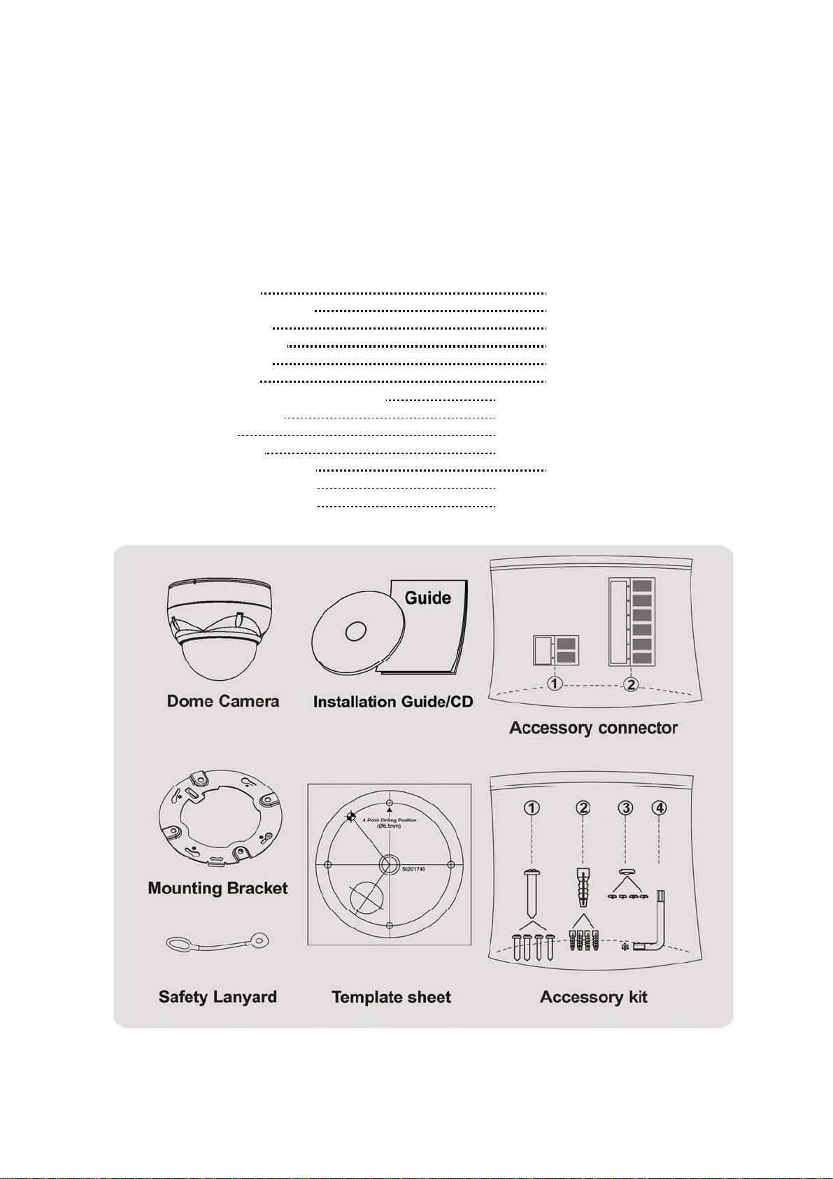
2.1 Package Contents............................................................................................................................2
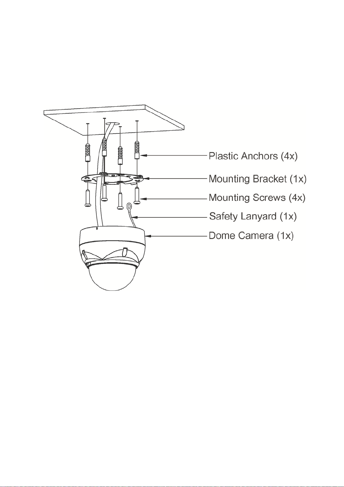
2.2 Installation.........................................................................................................................................3
2.3 Basic Configuration of Dome Camera System........................................................................6
2.4 Setting Dome Camera Address (ID)............................................................................................7
2.5 Connections......................................................................................................................................7
2.6 IP Assignment..................................................................................................................................8
2.7 Getting Started.................................................................................................................................9
Chapter 3 — Program and Operation...................................................................................10
3.1 Dome Camera Selection ..............................................................................................................10
3.2 Accessing the On-Screen Menu Utility....................................................................................10
3.3 How to control the On-Screen Menu Utility............................................................................10
3.4 Auto Scan (Shortcut: SCAN) .....................................................................................................11
3.5 Preset (Shortcut: PRST) .............................................................................................................13
3.6 Shortcut of Preset Program........................................................................................................14
3.7 Tour (Shortcut: TOUR) .................................................................................................................15
3.8 Pattern (Shortcut: PTRN).............................................................................................................17
3.9 Area Title..........................................................................................................................................18
3.10 Privacy Zone.................................................................................................................................19
3.11 Camera Menu................................................................................................................................20
3.12 Dome Setup ..................................................................................................................................23
3.13 Dome Communication ...............................................................................................................29
3.14 Function Run................................................................................................................................30
3.15 Factory Setup...............................................................................................................................30
Chapter 4 — Operation by Web Browser ............................................................................31
4.1 Access from a browser................................................................................................................31
4.2 Access from the internet.............................................................................................................32
4.3 Setting the admin password over a secure connection......................................................32
4.4 Live View Page...............................................................................................................................32
4.5 Network Camera Setup ................................................................................................................34
4.5.1 Basic Configuration...............................................................................................................35
1) Users............................................................................................................................ 35
2) Network........................................................................................................................ 36
3) Video & Image............................................................................................................. 37
V

VI
4) Audio............................................................................................................................ 39
5) Date & Time................................................................................................................. 40
4.5.2 Video & Image.........................................................................................................................41
1) Basic ............................................................................................................................ 41
2) Webcasting – Channel1.............................................................................................. 41
4.5.3 Audio .........................................................................................................................................42
4.5.4 Event..........................................................................................................................................42
1) Event-In........................................................................................................................ 42
2) Event-Out..................................................................................................................... 46
3) Event Map.................................................................................................................... 52
4.5.5 System ......................................................................................................................................54
1) Information.................................................................................................................. 54
2) Security........................................................................................................................ 54
3) Date & Time................................................................................................................. 57
4) Network........................................................................................................................ 58
5) Language..................................................................................................................... 65
6) Maintenance................................................................................................................ 65
7) Support........................................................................................................................ 66
4.5.6 About.........................................................................................................................................67
4.6 PTZ Control.....................................................................................................................................67
4.7 Help ...................................................................................................................................................68
4.8 Resetting to the factory default settings.................................................................................69
4.9 System Requirement for Web Browser ...................................................................................69
Appendix A — Specifications.................................................................................................70
Appendix B — Troubleshooting ............................................................................................73
Appendix C — Glossary...........................................................................................................73
Appendix D — Short Cut Key .................................................................................................76

Chapter 1 — Introduction
1.1 Features
The IPSDMV22D1 camera and the keyboard controller, PC software makes up the building
blocks for any surveillance/security system. Using multiple keyboard controllers and multiple
dome cameras, no place is too large for monitoring. Extensible and flexible architecture facilitates
remote control functions for a variety of external switching devices such as multiplexers and
DVRs.
Built-in optical power zoom camera with True Night Shot function
Dual video streams simultaneously at full frame rate in all resolutions up to D1 (720X480 in
NTSC, 720X576 in PAL) using Motion JPEG and H.264 (or MPEG-4)
Intelligent capabilities such as enhanced video motion detection
The encoder’s external inputs and outputs can be connected to devices such as sensors and
relays, enabling the system to react to alarms and activate lights or open/close doors.
Supports two-way audio
Logs all user access, and lists currently connected users. Also, full frame rate video can be
provided over HTTPS.
Interface Protocol: TCP/IP, UDP, IPv4/v6, HTTP, HTTPS, QoS, FTP, SNMP, uPnP, RTP,
RTSP, RTCP, DHCP, ARP
120 Preset positions with the individual Camera AE setup
4 Tours consist of Presets, Patterns, Auto Scans and other Tours can be programmed with
over 150 functions and Preset locations. While moving, each Preset scan can be watched in
smooth Vector Scan mode.
4 Auto Scans with the normal, the vector, and the random mode and the Endless Auto-Pan
with 13 speed steps
4 Patterns (up to 200 second) and 4 Privacy Zones
8 Area Titles
1 Alarm input / 1 Alarm output
Variable speed from 0.1/sec to 380/sec
Three Variable speed (SLOW, NORMAL, TURBO)
Turbo speed is 380/sec with Ctrl key pressed.
Pan / Tilt speed is inversely proportional to the zoom ratio with the option.
Maximum speed is 380/sec when Preset command.
Auto Calibration from 0.1to 6(Tilt range is 0to 180)
Programmable user preferences (alarm, preset, title, etc.)
180Digital Flip
Up to 255 selectable camera addresses
Multi-language Menu Display, Password Confirmation
Function Run menu using DVR without function key (Pattern, Scan, …)
Built-in RS-485 receiver driver
12VDC for Dome
Use satisfy clause 2.5 of IEC60950-1/UL60950-1 or Certified/Listed Class 2 power source only.
1

Chapter 2 — Installation and Configuration
2.1 Package Contents
The IPSDMV22D1 camera is design to a compact, small size, hard dome camera housing.
The housing is constructed of aluminum, steel and plastic. The housing is designed to be
mounted both wall and ceiling type.
The housing meets the Protection Classification IP66 standards for dust and moisture resistance.
* Dome Camera 1
* Installation Guide/CD 1
* Template Sheet 1
* Mounting Bracket 1
* Safety Lanyard 1
* Accessory Kit 1
1) Mounting screws (PH6 x 35.0) (4)
2) Plastic anchors (4)
3) O-Rings (4)
4) Torx wrench (1)
* Accessory Connector 1
1) 2Pin Terminal Block (1)
2) 6Pin Terminal Block (1)
2

2.2 Installation
The IPSDMV22D1 camera is for use in surface or pendent mounting applications and the
mounting member must be capable of supporting loads of up to 3.5lb (1.6kg). (Pendent mounting
must use pendent mount accessory.)
The dome camera’s mounting bracket should be attached to a structural object, such as hard
wood, wall stud or ceiling rafter that supports the weight of the dome camera.
CAUTION: A silicone rubber sealant must be applied to seal the housing to secure
waterproofing.
2.2.1 Locking Dome Camera
A. Make screw holes on the ceiling using the supplied mounting Template Sheet (Figure A).
B. Fix the Mounting Bracket using Anchors(4x) and Mounting Screws(4x) to the ceiling (Figure B).
C. Hook up the Safety Lanyard to the Safety Lanyard Hook of the Mounting Bracket (Figure C).
D. Align the locking tap on the bracket and the locking slot on the base of the dome (Figure D).
E. Turn the dome to the counterclockwise about 10 degree to the locked position (Figure E).
3

CAUTION: Before installing mounting bracket to surface pre-adjust the four mounting
screws "A" on the base of the dome camera to best match the mounting
bracket locked position. Unscrew the locking screw on the side of the dome's
base and fit the tab of the mounting bracket into the locking slot. Screws "A"
should not be too tight or too loose when the dome is in the locked position.
After setting the proper positions of screws "A" remove the mounting bracket
and install it to the proper surface. If it is too difficult to lock the dome in
position after the mounting bracket has been installed readjust the screws "A"
by unscrewing them a small amount and try to install dome camera again.
4

2.2.2 Heater Kit Installation
1. Assemble the Heater board to two bossed with screws.
Take a reference "B" in the bottom case as below.
2. Place the Heater in the slot "A".
Heater cable should be placed away from the Main board.
3. Plug the power connector to the socket "C"(J1) of the Heater board.
4. 12VDC is recommended to use for the camera power for stable operation with heater kit.
• HEATER (IF APPLICABLE)
Power Supply 12VDC
Power Consumption 10W
Heater ON at 59°F (15°C)
Heater OFF at 77°F (25°C)
• POWER
Use Certified/Listed Class 2 power source only.
5

2.3 Basic Configuration of Dome Camera System
No. Wire Color Description
1 Red: 12VDC+
White: 12VDC- Main Power: 2pin terminal
2
Black: GND
Gray: Alarm Input
Yellow: GND
Black&White: Alarm Output
Green: RS485+
Blue: RS485-
Alarm Input/Output, RS485: 6pin terminal
3 Black Ethernet: RJ45 Modular Jack
4 Yellow Video Composite Output: BNC Jack
5 Red Audio line output: RCA Jack
6 White Audio line input: RCA Jack
The IPSDMV22D1 camera must be installed by qualified service personnel in accordance with all
local and federal electrical and building codes.
6

2.4 Setting Dome Camera Address (ID)
To prevent damage, each dome camera must have a unique address (ID).
When installing multiple dome cameras using a multiplexer, it is suggested that the dome camera
address match the multiplexer port number.
The factory default setting is 1.
Refer to ‘3.13 Dome Communication’ section for detailed information.
2.5 Connections
• Connecting to the RJ-45
Connect a standard RJ-45 cable to the network port of the dome camera. Generally a cross-
over cable is used for directly connection to PC, while a direct cable is used for connection to a
hub.
• Connecting Alarms
AI (Alarm Input)
You can use external devices to signal the dome camera to react on events. Mechanical or
electrical switches can be wired to the AI (Alarm Input) and G (Ground) connectors.
Please see “4.5.4 Event > 1) Event-In > ②Alarm In” for configuring alarm input.
G (Ground)
NOTE: All the connectors marked G or GND are common.
Connect the ground side of the alarm input and/or alarm output to the G (Ground) connector.
AO (Alarm Output)
The dome camera can activate external devices such as buzzers or lights. Connect the device
to the AO (Alarm Output) and G (Ground) connectors.
Please see “4.5.4 Event > 2) Event-Out > ④Alarm Out” for configuring alarm output.
• Connecting to the RS485
The dome camera can be controlled remotely by an external device or control system, such as
a control keyboard, using RS485 half-duplex serial communications signals.
• Connecting Video out connector
Connect the video out (BNC) connector to the monitor or video input.
• Connecting the Power
Connect the power of 12VDC 2.0A for the dome camera.
When using a 12VDC adapter, connector the positive(+) pole to the ‘+’ position and
the negative(-) pole to the ‘-‘ position.
Use satisfy clause 2.5 of IEC60950-1/UL60950-1 or Certified/Listed Class 2 power source only.
7

2.6 IP Assignment
When the IPSDMV22D1 dome camera, encoder or decoder is first connected to the network it
has no IP address. So, it is necessary to allocate an IP address to the device with the
“SmartManager” utility on the CD.
1. Connect the dome camera / device to the network and power up.
2. Start SmartManager utility (Start > All programs > SmartManager > SmartManager), the main
window will be displayed, after a short while any network devices connected to the network will
be displayed in the list.
3. Select the dome camera on the list and click right button of the mouse.
You can see the pop-up menu as below.
4. Select Assign IPAddress. You can see Assign IP window. Enter the required IP address.
Note: For more information, refer to the SmartManager User’s Manual.
8

2.7 Getting Started
Once installed apply power to the IPSDMV22D1 dome camera. The dome camera will start a
configuration sequence.
OSD Position
The dome can move the OSD position in the OSD position setup.
(AREA TITLE) (AF AE)
(FUNC TITLE )
(CTRL KEY TO MOVE)
SAVE AND EXIT(ESC TO CANCEL)
(DOME ID…)
(ANGLE…)
OSD Position Setup
001 AF AE
EMPTY DATA
DOMEID:001
W→360.0 090.0
INFORMATION
DISPLAY
PRESET TITLE
A
REA TITLE
FUNCTION
UNDER RUNNING
CAMERA TITLE
CAMERA ID
VIEW DIRECTION
PAN & TILT ANGLE
STATUS of
FOCUS and AE
9

Chapter 3 — Program and Operation
3.1 Dome Camera Selection
Before you program or operate a dome camera, you must select the dome camera by pressing
No. + CAM keys.
Example:Pressing 1, 0+ CAM keys sequentially will select dome camera 10. The selected
dome camera ID will be displayed on the LCD monitor of the keyboard controller.
3.2 Accessing the On-Screen Menu Utility
You can call up the On-screen menu utility on your monitor by pressing the MENU key on the
keyboard controller, the following On-screen menu utility will appear:
DOME MENU
AUTO SCAN
PRESET
TOUR
PATTERN
AREA TITLE
PRIVACY ZONE
CAMERA
DOME SETUP
DOME COMMUNICATION
FUNCTION RUN
EXIT(ESC TO EXIT)
3.3 How to control the On-Screen Menu Utility
Function Button
Call the On-screen menu utility. MENU
Navigate through the menu items. Joystick up or down
Go into the sub-menu items. Joystick left or right or IRIS Open
Change value.
Enter the editing title mode. Joystick left or right or
Zoom handle twist or Tele , Wide
Change value of angle. CTRL + Joystick
Enter the changing angle mode. IRIS Open
Exit the changing angle mode. IRIS Close
Escape (EXIT) ESC
10

3.4 Auto Scan (Shortcut: SCAN)
The Auto Scan supports up to 5 programmed angles at user-programmable speeds. Follow
these steps to program Auto Scan:
AUTO SCAN SETUP
NUMBER : 01
TITLE : A01
MODE : NORMAL
SPEED : 5 STEP
START ANGLE : ----- -----
END ANGLE : ----- -----
SCAN DIR : CCW
SWAP : OFF
DWELL : 03 SEC
SAVE AND EXIT(ESC TO CANCEL)
NUMBER : 01 ~ 04, 09:AUTO PAN mode.
TITLE : up to 12 characters.
MODE : NORMAL, VECTOR, RANDOM (AUTO PAN mode: NORMAL, RANDOM only).
NORMAL : Move from start point to end point in panning only.
VECTOR : Move from start point to end point including tilt and zoom simultaneously and
linearly.
RANDOM : Move randomly between the start point and the end point.
SPEED : 01 ~ 13 step, the lower number means the slower speed.
SCAN DIR : Set the Scan direction, CCW(Counter Clock Wise), CW(Clock Wise).
SWAP : Swap the start point for the end point.
DWELL : Set the dwell time at the both end, 01 ~ 99 seconds.
1. Press the SCAN key to enter the Auto Scan menu directly. Or press the MENU key to display
the main menu on the monitor. Scroll to Auto Scan and push the Joystick to the right.
2. Select “NUMBER” and set the desired number by pushing the Joystick to the left or right.
3. Select “TITLE” and twist the Joystick to enter the title edit mode.
4. Twist the Joystick by changing the alphanumeric characters and move the next position.
Or move down to the character table and press the CTRL or IRIS Open key at the desired
character then the cursor position moves to the next position automatically. Push the Joystick
to the left or right at the “ALL DELETE” field to delete all characters. Push the Joystick to the
left or right at the “EXIT” field to finish title edit menu.
TITLE EDIT MENU
A01
*
A B C D E F G H I J
K L M N O P Q R S T
U V W X Y Z 0 1 2 3
4 5 6 7 8 9 ( )
ALL DELETE
EXIT(ESC TO EXIT)
5. Select “MODE” and “SPEED”.
11

6. Select “START ANGLE”. Hold down the CTRL key while selecting the start position using the
Joystick. Current panning position will be displayed. Release the CTRL key to complete the
selection of the start position. Or press the IRIS Open key then the “CTRL” displays. Move the
desired position and the zoom position. Press the IRIS Close key then the “CTRL” disappears.
To adjust at the 0.1 degree interval, twist the Joystick at the pan field and the tilt field. To
adjust at the one zoom interval, twist the Joystick at the zoom field.
7. Select “END ANGLE”. Hold down the CTRL key while moving the Joystick to select the end
position. The end position angle should be larger than start position. Release the CTRL key to
complete the selection of the end position. Or press the IRIS Open key then the “CTRL”
displays. Move the desired position and the zoom position. Press the IRIS Close key then the
“CTRL” disappears. To adjust at the 0.1 degree interval, twist the Joystick at the pan field
and the tilt field. To adjust at the one zoom interval, twist the Joystick at the zoom field.
8. Set “SCAN DIR” to CCW or CW.
9. Select “SWAP”, Set to ON, to exchange the start angle and the end angle.
10. Set “DWELL TIME”.
11. Select “SAVE AND EXIT” and push the Joystick to the right or press the IRIS Open key.
Press the ESC or IRIS Close key to exit the program without saving.
NOTE: Pressing the HOME key delete stored data at the angle field.
To set the position using the Preset position:
a. Before entering the Auto Scan menu, select a Preset position as a starting point for Auto Scan.
Example:2+ PRST keys and do step 1 to 5. In step 6, just press the Ctrl key at the start angle
position, the current position will be displayed as a start position.
b. Save and exit from the menu.
c. In normal mode, call a Preset to be the end point of Scan. Press 3+ PRST keys then press
the SCAN key to enter the Auto Scan menu. Move the cursor position to END ANGLE. Just
press the CTRL key at the end angle position. Save and exit from the menu.
Press the SCAN key on the angle field to display with the small OSD. Then the screen will show
as below.
AUTO SCAN AREA SETUP
(CTRL KEY)
NUMBER01
START : ----- -----
END : ----- -----
EXIT(ESC TO EXIT)
The setting procedure is the same as above.
NOTE: 09: AUTO-PAN mode (Endless panning)
12

3.5 Preset (Shortcut: PRST)
If you need to view specific places routinely, you should program Presets. A Preset is a
programmed video scene with automatic pan, tilt, zoom, focus and AE settings. Once
programmed, placing the number position and pressing the PRST key on your controller calls up
that Preset automatically. In addition, Presets may be assigned to alarm action or as the “home”
position for the dome camera. As many as 120 Presets, whose positions are saved in the dome’s
firmware, may be programmed.
There are two pages of Preset menu. Each page has 60 Presets. Pages can be scrolled by
pushing the Joystick to the left or right on the first or last No. of Preset.
PRESET SETUP
NUMBER : 001
TITLE : ---
CAMERA SET
DWELL : -- SEC
12345678901234567890
00 █**-----------------
02 --------------------
04 --------------------
NEXT PAGE
SAVE AND EXIT(ESC TO CANCEL)
-: blank Preset position
*: position has the Preset
█: current cursor position
Follow steps below to store the Preset positions:
1. Press the PRST key to enter the Preset menu directly. Or press the MENU key to display the
main menu on the monitor. Scroll to Preset and push the Joystick to the right.
2. Select the blank Preset position to be stored by pushing the Joystick up, down, right, or left.
3. After selecting a blank position, press and hold the CTRL key. Use the Joystick to control the
direction of the camera and lens.
4. After aiming the camera (view direction and lens control), release the CTRL key. The cursor
will be on the “TITLE” after saving data then twist the Joystick or press the Tele or Wide key
to edit the Preset title. Follow the procedure of the Auto Scan above to edit titles.
5. Select “CAMERA SET” and pushing the Joystick to the left or right. Then the Preset camera
setup displays.
PRESET CAMERA SETUP
FOCUS : AUTO
AE SETUP
SAVE AND EXIT(ESC TO CANCEL)
Set FOCUS : AUTO, MANUAL, ONE PUSH
Select “AE SETUP” and pushing the Joystick to the left or right. Then the AE setup displays.
Refer to the AE SETUP in the camera setup.
13

6. Set “DWELL TIME”. (03 ~ 99 seconds)
7. To select the next page of Presets, scroll the page by pushing the Joystick to the left on the
first and last columns of the menu.
8. Repeat step 2 through 7 for each additional Preset position.
9. Select “SAVE AND EXIT” and push the Joystick to the right or press the IRIS Open key.
Press the ESC or IRIS Close key to exit the program without saving.
NOTE: Press the HOME key at programmed Preset position(*) to delete a programmed
Preset view.
The position, which is marked with the *, already has the Preset view assigned. To review the
stored Preset, press the PRST key on the *. The camera will show the stored Preset scene.
PRESET AREA SETUP
(CTRL KEY)
NUMBER 001
PAN TILT
000.0 000.0
EXIT(ESC TO EXIT)
Hold down the CTRL key while selecting the desired scene using the Joystick. Current position
will be displayed. Release the CTRL key to complete. Or Press the IRIS Open key then the
“CTRL” displays. Move the desired position and the zoom position. Press the IRIS Close key
then the “CTRL” disappears. Select “EXIT” and push the Joystick to the right.
3.6 Shortcut of Preset Program
After selecting the desired scene, press No. (1to 120), and press the CTRL and PRST keys
subsequently. The current view will be stored to the selected Preset number if the Preset number
is empty. If selected Preset number is not empty, “OVER WRITE” message will be displayed on
the monitor and select the “OK” and push the Joystick to the right to overwrite.
Example: 1 , 0 , 1 + CTRL + PRST keys will store current view as Preset no. 101. In this case,
focus will be programmed as Auto, dwell time will be set to 3 second, and the current
AE mode will be programmed.
14
Table of contents
Other ATV Security Camera manuals