ATX QFCT User manual

QFCT 1310nm 1GHz Quality Fiber CATV Transmitter
Installation & Operation Manual
Q-SERIES
®
Optical

Although every effort has been taken to ensure the accuracy of this document it may be necessary, without notice, to make amendments or correct omissions.
Specications subject to change without notice.
SignalOn®Series, MAXNET®, HFC Enhance®, PCI Filters®, Q-Series®& FiberLinx®are registered trademarks of ATX in the United States and/or other countries. SMACSM is a
service mark of ATX in the United States and/or other countries. Products or features contained herein may be covered by one or more U.S. or foreign patents. Other non-ATX
product and company names in this manual are the property of their respective companies.

Q-Series®Optical – QFCT 1310nm 1 GHz Quality Fiber CATV Transmitter – Installation & Operation Manual i
TABLE OF CONTENTS
1. OPERATION NOTICE................................................... 1-1
2. SYSTEM DESCRIPTION ................................................ 2-1
3. OPERATION .......................................................... 3-1
3.1 General Description ............................................... 3-1
3.2 Start-up Main Menu ............................................... 3-1
4. SPECIFICATIONS...................................................... 4-1
5 SERVICE & SUPPORT.................................................. 5-1
5.1 Contact ATX Networks ............................................. 5-1
5.2 Warranty Information .............................................. 5-1

ii Q-Series®Optical – QFCT 1310nm 1 GHz Quality Fiber CATV Transmitter – Installation & Operation Manual
This page intentionally left blank

Q-Series®Optical – QFCT 1310nm 1 GHz Quality Fiber CATV Transmitter – Installation & Operation Manual 1-1
CHAPTER 1: OPERATION NOTICE
OPERATION NOTICE
1. Operation Notice
ATX Networks strongly advises you to read the following safety instructions prior to installing and operating this equipment.
1. The transmitter should have a good grounding with a grounding resistance<4Ω.
2. The machine utilizes a high performance, high reliability, and steady voltage switching power supply. It has constant
voltage overow protection and can work in 110~240 VAC electrical networks. The micro-processor monitors the
output DC voltage.
3. In order to make sure reection loss is =45dB, use APC style connectors; other types (such as SC/PC) are not
designed to mate with the QFCT1310 APC style optical connector. Keep the connector clean when installing.
4. Do not activate the transmitter without the ber cable attached or without the ber output port covered. Harmful laser
radiation is emitted which can cause harm, especially to the eyes.
5. RF level determines the OMI of the laser and the system index (CNR, CTB, CSO). When at 59 route PAL-D, its RF
level is 20dBmV. Suppose channel is N: Si(N)=20+10Lg(59/N) (dBmV)
6. CNR and Channel N: CNR(N)=CNR(59)+10Lg(59/N) (dB)
INVISIBLE LASER RADIATION
DO NOT VIEW DIRECTLY
WITH OPTICAL INSTRUMENT
CLASS 1M LASER PRODUCT
CAUTION

1-2 Q-Series®Optical – QFCT 1310nm 1 GHz Quality Fiber CATV Transmitter – Installation & Operation Manual
CHAPTER 1: OPERATION NOTICE
This page intentionally left blank

Q-Series®Optical – QFCT 1310nm 1 GHz Quality Fiber CATV Transmitter – Installation & Operation Manual 2-1
CHAPTER 2: SYSTEM DESCRIPTION
SYSTEM DESCRIPTION
2. System Description
2.1 General Description
QFCT1310 series of AM laser transmitters deliver signal transmission of NTSC, PAL, digital or compressed digital information
for CATV in private networking application.
The unit is packaged in a rack-mounted casing of 1.75-inch height (1RU) and 19-inch width. Each unit is equipped with a self-
governed power supply with 110-240V AC input.
2.2 Product Highlights
1. Transmits NTSC, PAL, analog, digital, or compressed digital signals
2. 1310nm operation
3. Optically isolated distributed AM feedback laser
4. 47-1000MHz RF input bandwidth
5. Up to 78 NTSC channels
6. Front panel RF test point
7. Low RF drive levels are required for the built-in RF amplier
8. Industry standard select monitoring interface RS-232

2-2 Q-Series®Optical – QFCT 1310nm 1 GHz Quality Fiber CATV Transmitter – Installation & Operation Manual
CHAPTER 2: SYSTEM DESCRIPTION
This page intentionally left blank

Q-Series®Optical – QFCT 1310nm 1 GHz Quality Fiber CATV Transmitter – Installation & Operation Manual 3-1
CHAPTER 3: OPERATION
OPERATION
3. Operation
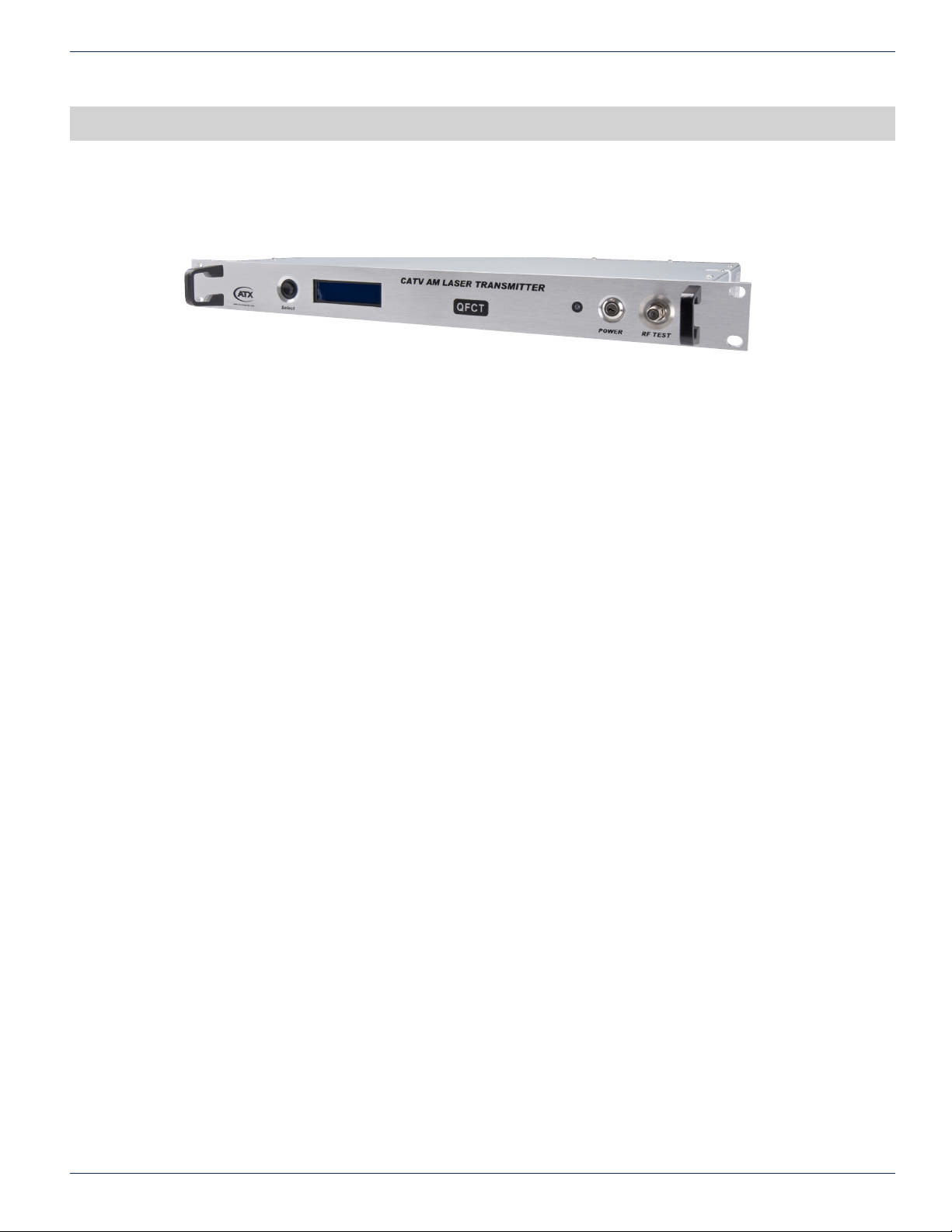
This section of the manual will give an overview of the available menus in the QFCT1310 series transmitter. All instructions in
this section refer to the representation of the front panel shown in the diagram below. The user can scroll through the menus
by using the push button that is on the front panel, located in the right of the LCD screen.
3.1 General Description
There is a status LED located to the left of the power supply key switch on the front panel. When it is green, the device is
working properly. When it is red, the laser has encountered a fault condition. When it is ashing red, there is an alarm.
• Plug in power supply. The digital panel will display “READY: KEY OFF”, and there will be Red light.
• In order to protect the laser, there is time-delay function. After turning on with the key, the laser initialize after 10
seconds. Then the LED will turn to Green from Red and the digital panel will display the model of the machine.
3.2 Start-up Main Menu
Press select button and the following menu will be displayed in sequence.
• Menu #1
ATX Networks, INC
(800) 565-7488
• Menu #2
LD BIAS
Read-only menu, displays laser bias temperature
• Menu #3
COOLING/HEATING
Read-only menu, displays the amount of current that the thermoelectric cooler requires to maintain the laser
temperature at nominal 25°C
• Menu #4
UNIT TEMP
Read-only menu, tells the system temperature
• Menu #5
+5V READS
Read-only menu, displays the voltage +5V
• Menu #6
-5V READS
Read-only menu, displays the voltage -5V
• Menu #7
+24V READS
Read-only menu, displays the voltage +24V
• Menu #8
S/N
Read-only menu, displays the serial number

3-2 Q-Series®Optical – QFCT 1310nm 1 GHz Quality Fiber CATV Transmitter – Installation & Operation Manual
CHAPTER 3: OPERATION
1. If the LCD screen displays “INTERLOCK”, and the red LED is ashing, it means that the RS-232 port at the back
panel is loose.
2. If RF input level is too high, there will be an alarm (LED ashing red). You should shut off the power, adjust RF input
level to nominal range and then apply power to the transmitter.
3. +5V voltage (+5V READS) >±0.5V alarm.
-5V voltage (-5V READS) >±0.5V alarm.
4. If any fault occurred, there will be alarm (LED ashing red). Microprocessor will shut off the laser automatically, and
digital panel will show the reason of the fault.

Q-Series®Optical – QFCT 1310nm 1 GHz Quality Fiber CATV Transmitter – Installation & Operation Manual 4-1
CHAPTER 4: SPECIFICATIONS
SPECIFICATIONS
4. Specications

4-2 Q-Series®Optical – QFCT 1310nm 1 GHz Quality Fiber CATV Transmitter – Installation & Operation Manual
CHAPTER 4: SPECIFICATIONS
This page intentionally left blank

Q-Series®Optical – QFCT 1310nm 1 GHz Quality Fiber CATV Transmitter – Installation & Operation Manual 5-1
CHAPTER 5: SERVICE & SUPPORT
SERVICE & SUPPORT
5. Service & Support
5.1 Contact ATX Networks
Please contact ATX Technical Support for assistance with any ATX products. Please contact ATX Customer Service to obtain
a valid RMA number for any ATX products that require service and are in or out-of-warranty before returning a failed module
to the factory.
RF Products
(MAXNET, SignalOn, HFC Enhance, PCI Filters, Q-Series, SCN, SMAC, FiberLinx)
TECHNICAL SUPPORT
Tel: (905) 428-6068 – press *3 then press 2
Toll Free: (800) 565-7488 – press *3 then press 2 (USA & Canada only)
Email: [email protected]
CUSTOMER SERVICE
ATX Networks
1-501 Clements Road West
Ajax, ON L1S 7H4 Canada
Tel: (905) 428-6068 – press *1
Toll Free: (800) 565-7488 – press *1 (USA & Canada only)
Fax: (905) 427-1964
Toll Free Fax: (866) 427-1964 (USA & Canada only)
Email: [email protected]
Web: www.atxnetworks.com
5.2 Warranty Information
The ATX Networks’ products have a one year warranty and is subject to ATX Networks’ standard warrantee terms.
There are no user serviceable components inside the unit. The warranty is void if the unit is opened or is damaged due to
misuse.

Printed in Canada Rev. 11/17 (ANW1003)
1-501 Clements Road West, Ajax, ON L1S 7H4 Canada
Tel +1 (905) 428-6068 Toll Free +1 (800) 565-7488
Fax +1 (905) 427-1964 Toll Free Fax +1 (866) 427-1964
www.atxnetworks.com [email protected]
Table of contents
Other ATX Transmitter manuals
Popular Transmitter manuals by other brands

Horizon Hobby
Horizon Hobby Spektrum DX3R instruction manual

Long Range Systems
Long Range Systems LRS Connect TX-7471 user manual

Farpointe Data
Farpointe Data Ranger quick start guide

Black Widow Security
Black Widow Security BW FM Net installation manual

Siemens
Siemens SITRANS LR560 Compact operating instructions

F&F
F&F FW-GS-230-B manual

Shure
Shure UR1M Specifications

Televes
Televes FiberKom 237301 manual

HK Instruments
HK Instruments DPT-MOD Series installation instructions

Lectrosonics
Lectrosonics HMA-941 Series quick start guide

Phoenix
Phoenix PHS300-x installation guide

BWI Eagle
BWI Eagle AIR-EAGLE SR PLUS Product information bulletin