TMG TMG-AB72 User manual

WWW.TMGINDUSTRIAL.COM P24/25 Toll Free:1-877-761-2819

WWW.TMGINDUSTRIAL.COM P1/25 Toll Free: 1-877-761-2819
TABLE OF CONTENTS
GENERAL COMMENTS.................................................................. 2
SAFETY PRECAUTIONS ............................................................... 3
SAFETY DECALS............................................................................ 5
MAIN SPECIFICATIONS.................................................................. 6
SKID STEER REQUIREMENTS ...................................................... 7
IDENTIFICATIONS OF MAIN COMPONENTS............................... 9
OPERATING INSTRUCTIONS ....................................................... 10
Attaching
Check before operation
Angling of the broom
Sweeping operation
Disconnecting
Transporting
Storage
MAINTENANCE ........................................................................... 20
LONG TERM STORAGE................................................................. 20
PARTS CHART................................................................................ 21

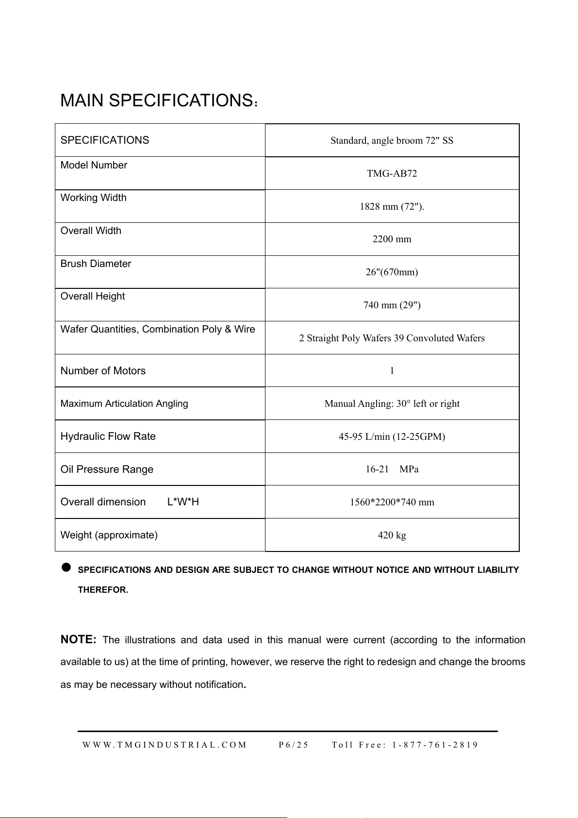
WWW.TMGINDUSTRIAL.COM P2/25 Toll Free: 1-877-761-2819
GENERAL COMMENTS
Congratulations on the purchase of a new Angle broom. This product has been designed
and built to clean and handle all types of material including fine dirt, gravel, mud, millings
and other debris. You or any other people who will be assembling, operating, maintaining,
or working with this product are required to read and completely understand the
information and instructions contained in this manual. If any questions about it, please
obtain further assistance by contacting the dealer from which this product was purchased.
Your attachment was carefully designed and manufactured to give you many years of
dependable service. Only minor maintenance (such as cleaning and lubricating) is required
to keep it in top working condition. Be sure to observe all maintenance procedures and
safety precautions in this manual, on the safety decals located on the attachment, and on
any equipment on which the attachment is mounted.
The purpose of this manual is to assist in assembling, mounting, operating, and
maintaining your Hydraulic Angle broom. It can help you to do a better, safer job.
Read this manual carefully, and become familiar with the operating procedures before
attempting to operate your attachment.
The illustrations and data used in this manual were current at the time of printing, but due
to possible engineering and/or production changes, this product may vary slightly in detail.
Our company reserves the right to redesign and/or change components as may be
necessary without notification to anyone.
REMEMBER: never let anyone operate this attachment without them having read and
completely understand the “Safety ” and “Operating Instructions” sections of this manual,
or having them be fully trained by an experienced, qualified person who has read and
completely understands the “Safety Precautions” and Operating Instructions”.
SAFETY PRECAUTIONS
THE USE OF THIS EQUIPMENT IS SUBJECT TO CERTAIN HAZARDS WHICH CANNOT BE
PROTECTED AGAINST MECHANICAL MEANS OR PRODUCT DESIGN. ALL OPERATORS OF
THIS EQUIPMENT MUST READ AND UNDERSTAND THIS ENTIRE MANUAL, PAYING
PARTICULAR ATTENTION TO SAFETY AND OPERATING INSTRUCTIONS, PRIOR TO USING
THE HYDRAULIC ATTACHMENT. IF THERE IS SOMETHING IN THIS MANUAL YOU DO NOT
UNDERSTAND, ASK YOUR SUPERVISOR TO EXPLAIN IT TO YOU. FAILURE TO OBSERVE
THESE SAFETY PRECAUTIONS CAN RESULT IN DEATH OR SERIOUS INJURY OR SERIOUS
EQUIPMENT DAMAGE.

WWW.TMGINDUSTRIAL.COM P3/25 Toll Free: 1-877-761-2819
All bystanders should be kept a minimum of 10 feet (3 meters) away from working area of
the attachment.
PROTECT AGAINST FLYING DEBRIS: Always wear an OSHA approved hard hat and
safety eye protection when operating or servicing this equipment. Do not wear loose fitting
clothing, flopping cuffs, dangling neckties and scarves, or rings and wrist watches that can catch
moving parts.
An operator must not use drugs or alcohol which can change his alertness or coordination.
An operator taking prescription or over-the-counter drugs should seek medical advise on whether
or not he can safely operate equipment.
Never alter or remove any safety decals or shields. Replace all missing or damaged safety
decals or safety shields. Check this manual for location of these items and replace immediately if
damaged or illegible.
Never adjust a relief valve for pressure higher than recommended by vehicle manufacturer.
Whenever changing or installing this or other attachments, make sure all connections are
securely fastened. Travel only with the attachment in a safe transport position to prevent
uncontrolled movement. Drive slowly over rough ground and on slopes. Remove attachment from
vehicle when transporting to and from job site.
LOWER OR SUPPORT RAISED EQUIPMENT: Before exiting vehicle, lower attachment to
ground, turn off vehicle engine and lock vehicle brakes. Do not work under raised booms without
supporting them. Do not use support material made of concrete blocks, logs, buckets, barrels or
any other material that could suddenly collapse or shift positions. Make sure support material is
solid, not decayed, warped, twisted, or tapered. Lower booms and the attachment to ground level
or onto blocks before leaving the cab or operator’s station.
Never check a pressurized system for leaks with your bare hand. Oil escaping from pinhole
leaks under pressure can penetrate skin and could cause serious infection. Hold a piece of
cardboard up next to suspected leaks and wear a face shield or safety eye protection. If any fluid
is injected into the skin, it must be removed immediately by a doctor familiar with this type of
injury.
Before disconnecting hydraulic lines or fittings, be sure to relieve all pressure by cycling all
hydraulic controls after shutdown. Remember hydraulic systems are under pressure whenever
the engine is running and may hold pressure after shutdown. Before applying pressure to the
system make sure all connection are tight and that there is no damage to lines, fittings and hoses.
Flow and pressure gauges, fittings and hoses must have a continuous operating pressure

WWW.TMGINDUSTRIAL.COM P4/25 Toll Free: 1-877-761-2819
rating of at least 25% higher than highest pressures of the system.
Avoid steep hillside operation which could cause the vehicle to overturn. Consult your
vehicle operator’s and safety manuals for maximum incline allowable.
Never perform any work on an attachment unless you are authorized and qualified to do so.
Always read the operator service manual(s) before any repair is made. After completing
maintenance or repair, check for correct functioning of the attachment. If not functioning properly
always tag “DO NOT OPERATE” until all problems are corrected.
This manual covers the safe use, installation, operation and service instructions for the
attachment only. Always read the operating and safety manuals prepared for your vehicle and any
other attachments before using them.
EQUIPMENT SAFETY PRECAUTIONS
CAUTION! Avoid pinch points and be aware of rotating parts when operating
the attachments.
WARNING! ROTATING OBJECTS!
•Check your work area, for objects that could harm the operator or others if thrown by
the attachment. Remove these items before working.
• Do not carry load with arms in the raised position. Always carry loads close to the
ground. Do not step off platform with load raised.
• Use extra care when loading or unloading the machine onto a trailer or truck.
• Slow down before turning. Sharp turns on any terrain may cause loss of control.
• Always lower the loader arms to the ground; shut off the engine and remove the key
before getting off the unit.
• Turn off engine before performing maintenance. If lift arms must be left raised for
maintenance or any other reason, use a positive lift arm lock to secure the arms in place.
Serious damage or personal injury could result from lift arms accidentally lowering.

WWW.TMGINDUSTRIAL.COM P5/25 Toll Free: 1-877-761-2819
SAFETY DECALS
1、WARNING
READ AND UNDERSTAND OPERATING INSTRUCTIONS AND SAFETY INFORMATION
PRIOR TO OPERATING YOUR ATTACHMENT.。
2、PINCH POINT HAZARD
3、FLYING OBJECTS HAZARD
4、HIGH PRESSURE FLUID HAZARD

WWW.TMGINDUSTRIAL.COM P6/25 Toll Free: 1-877-761-2819
MAIN SPECIFICATIONS:
SPECIFICATIONS AND DESIGN ARE SUBJECT TO CHANGE WITHOUT NOTICE AND WITHOUT LIABILITY
THEREFOR.
NOTE: The illustrations and data used in this manual were current (according to the information
available to us) at the time of printing, however, we reserve the right to redesign and change the brooms
as may be necessary without notification.
SPECIFICATIONS Standard, angle broom 72" SS
Model Number TMG-AB72
Working Width 1828 mm (72").
Overall Width 2200 mm
Brush Diameter 26"(670mm)
Overall Height 740 mm (29")
Wafer Quantities, Combination Poly & Wire 2 Straight Poly Wafers 39 Convoluted Wafers
Number of Motors 1
Maximum Articulation Angling Manual Angling: 30° left or right
Hydraulic Flow Rate 45-95 L/min (12-25GPM)
Oil Pressure Range 16-21 MPa
Overall dimension L*W*H 1560*2200*740 mm
Weight (approximate) 420 kg

WWW.TMGINDUSTRIAL.COM P7/25 Toll Free: 1-877-761-2819
SKID STEER LOADER REQUIREMENTS
The Angle broom is designed to attach to skid steers with the following minimum requirements:
SAE Lift Capacity . . . . . . . . . . . . . . .. . . . . . . . . . . . . . . . . . 1200 lbs.
Hitch Type . . . . . . . . . . . . . . . . . . . . . . Universal Quick Attach Hitch
Hydraulic Pressure Rating . . . . . . . . . . . . . . . . . . . . 1600 - 2200 PSI.
Motors & Hoses . . . . . . . . . . . . . . . . . . . . . . . . . . . . . . . 10 - 23 GPM.
Hydraulic Hoses . . . . . . . . . . . . . . 3 - Hydraulic couplings: Inlet/Outlet/Case drain line
Connection:withFlat‐FacedCouplers:
1/2” Flat-face Quick Coupling (male) & 1/2” Flat-face Quick Coupling (female)
3/8” Flat-face Quick Coupling (female);(for case drain line if equipped on skid steer loader)
Caution:
DO NOT EXCEED 23 GALLONS PER MINUTE!!
Severe injury or death could occur due to the increased RPM.
CAUTION: NEVER store angle broom with weight on bristles. This will cause warping of
bristles. ALWAYS store on stands keeping broom bristles off the ground.
DANGER!ROTATING PARTS HAZARD! STAY BACK!
OBJECTSCANBETHROWN!
DO NOT operate near bystanders.
IMPORTANT:Theattachmentshavebeenequippedwith3hoses.Hosefittingsandquickcouplers
totheskidsteerloaderareoptional.Ifnotpurchasedwithit,theycanbepurchasedfromyour
dealerorlocalmarket.Makesurethecouplerscompatibletoattachtheunittotheskid‐steer
auxiliaryhydrauliccouplers,includingthetype,thedimensionsandthequantities.
NOTE! DEALERS AND/OR OWNERS MUST DETERMINE THAT COMPATIBILITY
BETWEEN THE SKID STEER LOADER AND ATTACHMENT EXISTS.
Compatibility includes, but is not limited to items such as operator clearance, hitch
(mounting assembly) component strength, and hydraulics.
The 3rd hose and quick coupler for case drain line is only an option. It is only used for
attaching to the skid steer loader equipped with Case drain line along its path to the
sump/tank. If not equipped, then just remove the hose of the attachment.

WWW.TMGINDUSTRIAL.COM P8/25 Toll Free: 1-877-761-2819
The angle broom was supplied with hoses. Proper hose end fittings and/or quick couplers must be
purchased as the hose threads.
Hose End Fittings:............................ One hose end must be metric M18X1.5. The fitting for the other
end can be whatever you determine to be the most beneficial to making the connection to your skid steer.

WWW.TMGINDUSTRIAL.COM P9/25 Toll Free: 1-877-761-2819
IDENTIFICATIONS OF MAIN COMPONENTS
Rest support
bracket
Poly/Steel broom bristle
wafe
r
ki
t
Angle broom
main frame
Hydraulic
motor
Articulation pin /Angle
Pivot
Motor shield
Hitch attach-
p
late
Hydraulic
hoses
Shaft hub, non-motor
en
d
Pin hole of
connectin
g
p
late
Connecting top angled
bars (attachment flange)

WWW.TMGINDUSTRIAL.COM P10/25 Toll Free: 1-877-761-2819
OPERATING INSTRUCTIONS:
*INSTALLATION INSTRUCTIONS
The installation of your ATTACHMENT is the same for any other powered
attachment for your skid steer loader:
NOTE:
1. Remove any attachments from the front of the loader.
2. Following all standard safety practices and the instructions for installing an attachment in
your skid-steer operator's manual, install the ATTACHMENT onto your skid-steer.
NOTE: It is important to make sure the locking mechanism on your quick
attach is engaged, therefore locking the attachment onto the skid-steer.
DANGER
A Crushing Hazard exists when hooking-up equipment. Do not allow anyone to stand between skid steer
loader and implement while hooking-up to implement. Do not operate hydraulics while someone is near the
skid steer loader or implement.
CAUTION
Make sure your skid steer loader hitch is properly attached to the Angle broom hitch. It must be secured
under the Angle broom top angle bars and loader hitch plate lock handles must be locked down with locking
pins extending fully through bottom slots in the Angle broom hitch. An improperly attached Angle broom
can come loose and fall.
WARNING
Never go underneath equipment (lowered to the ground or raised) unless it is properly blocked and secured.
Never place any part of the body underneath equipment or between moveable parts even when the engine
has been turned off. Hydraulic system leak down, hydraulic system failures, mechanical failures, or
movement of control levers can cause equipment to drop or rotate unexpectedly and cause severe injury.

WWW.TMGINDUSTRIAL.COM P11/25 Toll Free: 1-877-761-2819
*ATTACHING TO SKID STEER LOADER:
1. Check for and remove any debris in the hitch point areas before attaching to Angle broom to skid
steer loader.
Read the skid steer operator's manual connecting and removing instructions.
Position hydraulic hoses so they will not be pinched when connecting the angle broom.
The skid steer lock handles should be in the unlocked position and the lock pins retracted.
2. Drive skid steer loader slowly to the Angle broom and carefully align the skid steer to the angle
broom, making sure hitch plate on the skid steer loader is parallel with the Angle broom’s top angle
bars.
3. Rotate top of skid steer loader tilt arms slightly forward.
4. Position top of skid steer loader hitch plate under the top angled bars and slowly raise loader
hitch plate up until hitch plate is seated under the top angle bars (attachment flange). Lower skid
steer lift arms to their lowest position
LOCK HANDLES.
REFER TO THE
MANUAL OF SKID
STEER LOADER.
LOCK PIN OF
SKID STEERS
MOUTING HITCH PLATE

WWW.TMGINDUSTRIAL.COM P12/25 Toll Free: 1-877-761-2819
5. Rotate top of skid steer loader tilt arms back until Angle broom makes full contact with face of
hitch plate so the lock handles can be engaged.
6. Push lock handles on the skid steer loader hitch down. Make sure lock pins go through bottom
slots in the Angle broom hitch and handles are fully locked down.
The lock pins must be completely extended and secured into the slots provided on the angle
broom.

WWW.TMGINDUSTRIAL.COM P13/25 Toll Free: 1-877-761-2819
Hydraulic Hose Hook-up
Connect hydraulic hoses to skid steer auxiliary quick couplers.
2 or 3 quick couplers should be connected according to the equipment on the skid steer loader. If only 2
couplers are equipped on the skid steer without the case drain line, then just remove the 3rd one and plug the
outlet port accordingly.
DANGER
Hydraulic fluid under high pressure can penetrate skin. Wear protective gloves
and safety glasses or goggles when working with hydraulic systems. Use a piece
of cardboard or wood rather than hands when searching for hydraulic leaks.
If hydraulic fluid is injected into the skin or eyes, it must be treated by
a doctor familiar with this type of injury within a few hours or gangrene
may result. DO NOT DELAY.
IMPORTANT: Collect and dispose all oil spills and leaks in an environmentally safe manner.
IMPORTANT: Hose routing is the responsibility of the owner/operator of the Angle broom. Pinched
and/or stretched hoses are not covered under the warranty.
Section 2: Equipment Hook-up & Unhook
IMPORTANT: Make sure all coupler fittings are clean before connecting them together.
Two high pressure hydraulic outlets are required for the hydraulic motor.
1. Route hydraulic hoses along the most convenient path to access your skid steer loader.
2. Clean quick connect couplers of dirt and then connect couplers to the skid steer couplers.
Make sure quick connect couplers have fully engaged.
If they have not, check the following:
a. Make sure couplers are same size and type.
b. Make sure hydraulic pressure has been released.

WWW.TMGINDUSTRIAL.COM P14/25 Toll Free: 1-877-761-2819
NOTE:
The ATTACHMENT attaches to the toolbar/quick-attach mechanism of your skid-steer
loader. Due to this arrangement, thorough knowledge of the skid-steer controls is
necessary for machine operation. Read and understand your skid steer operator's manual
for information regarding skid-steer operation before attempting to use the ATTACHMENT.
Follow all installation instructions for the proper installation of the unit onto your skid-steer
before attempting to operate your ATTACHMENT.
Now the mechanism and hydraulic device have been
properly connected to be ready for working.
CONNECT QUICK
COUPLERS
REFER TO THE MANUAL
OF SKID STEER LOADER

WWW.TMGINDUSTRIAL.COM P15/25 Toll Free: 1-877-761-2819
Check Equipment before operation
It is important to check clearance before putting the Angle broom into operation. Make sure hydraulic hoses
are long enough and won’t become pinched or entangled in the equipment.
1. Visually inspect hydraulic hoses for possible pinch points and shortness. If needed, make hose
adjustments before putting equipment into service.
2. Start skid steer/tractor and raise loader arms high enough to tilt the hitch plate fully down without Angle
broom making contact with the ground.
3. Fully extend and retract hydraulic cylinders on the end of the skid steer loader arms while watching for
interferences between skid steer loader and Angle broom frame.
4. Raise skid steer/ loader arms fully up and repeat steps above.
IMPORTANT: Make sure hydraulic hoses are long enough and properly secured so that they do
not become stretched or pinched through their full range of motions.
NOTICE:
■ Maximum oil flow is 25 gpm (94.8 liters/min) at 3000 psi (206.8 bars). See the skid steer
manual for oil flow specifications.
Before Each Use
Run the angle broom with the skid steer at a slow idle. Check for hydraulic leaks or other problems and
make corrections, if necessary, before using the angle broom.
During Use
Carry the angle broom low to the ground so that the operator has good visibility and stability. Avoid any sudden
movements. Avoid excessive downward pressure on the brush sections to prevent excessive wear. A two to four inch
wide pattern for the broom is sufficient for most applications. Ensure that the adjustment bolts are equally adjusted in
order to prevent an uneven wear pattern.

WWW.TMGINDUSTRIAL.COM P16/25 Toll Free: 1-877-761-2819
Operating instructions (continued)
Operation of sweeping
The angle broom is capable of, and in fact intended to be utilized for, sweeping away dirt, light
snow and other debris. Directions for use are as follows:
1. Start the skid steer at idle speed and raise the brush head.
2. Use low engine speeds to save wear and tear on the angle broom and to prevent dust from
billowing up during sweeping.
NOTE: Donotengagethebrushathighenginespeeds.Thisdamagestheanglebroomandmotor.
3. Engage the brush head and lower it to the ground.
4. Gradually increase skid steer engine rpm to sweeping speed. Travel forward at 5 mph or less.
NOTE: Avoidbroomdamage.Reducetravelspeedtoavoidhittingimmovableobjects.
Before sweeping, make sure the parking stands are raised. It is required to keep the brush off the ground when the
broom is not attached to the skid steer loader or if the skid steer loader will be parked for some time.
To sweep:
1. Adjust broom in direction you want to sweep debris.
2. Raise broom so bristles are clear of ground with loader engine at idle.
3. Engage broom, lower to ground and gradually increase engine rpm.
4. Proceed forward slowly (5 mph or less)
5. Note: excessive down pressure on bristles will cause accelerated broom wear.
Never operate this attachment in the proximity of any utilities laying on the ground surface. Always inspect area
before starting the sweeping process to avoid any electrical wires or cables that might be laying on the surface.
Moving or engaging the broom with bystanders in the area could result in Death or Serious Injury. Before engaging
the broom hydraulics, always make sure the area is clear of bystanders. Never operate the broom when bystanders are in
proximity of the work area that could result in Minor or Serious Injury from flying debris. Flying debris could result in Death or
Serious Injury.

WWW.TMGINDUSTRIAL.COM P17/25 Toll Free: 1-877-761-2819
Angling the Broom
Angling the broom will control the direction debris will leave the broom. Angling the brush head the same
direction as the wind will also help reduce the amount of material that blows onto the operator and the area
just swept.
ManualAngleModels:Raisetheattachmentabout8”(200mm)offthegroundsurface.Shutofftheskidsteer
engine
1.Exitthecabandremovetheangle‐lockpinlocatedinthecenterofthebroommountingbracket.
2.Whenthelockpinhasbeenpulled,thebroomheadcanbepivoted.Swingthebrushheadbyhandtothe
desiredangle.
3.Insertthepininthenearestholetolockthebroomheadinplace.
Themanualanglekithasholesforstraightsweepingand30°or15°anglesweepingrightorleft.
Sweeping
Carry the broom low to the ground so that the operator has good visibility and stability. Avoid any sudden
movements.
Avoid excessive downward pressure on the brush sections to prevent excessive wear. A two to four inch
wide pattern is sufficient for most applications. Ensure that the adjustment bolts are equally adjusted in order
to prevent an uneven wear pattern.
SLOW DOWN!!
The brooms are powered with the auxiliary hydraulic system on the skid steer power unit. Brush speed can
be reduced by reducing engine rpm.
NOTE: Always reduce engine rpm when possible, to reduce hydraulic oil temperature and noise.
Notice the direction of the bristle rotation and if not correct, reverse the flow by selecting the opposite
direction on the auxiliary circuit switch, pedal or lever.
When beginning to use the broom, start with the middle of its operating range. Then adjust the engine rpm
later, depending on the sweeping requirement.
Lower the broom until the brush is near the ground.With the skid steer engine at a low speed, engage the

WWW.TMGINDUSTRIAL.COM P18/25 Toll Free: 1-877-761-2819
auxiliary hydraulic system. Slowly increase the engine speed until the desired brush speed is reached. To
stop, slow the skid steer engine speed to idle and then disengage the auxiliary hydraulic system.
Slowly lower the broom until ground contact is made.
Engage the skid steer drive and move the skid steer in the forward direction to start sweeping.
NOTE: Do not allow the broom to drop violently on to the ground. Lower it slowly to allow the brush bristles to
gradually start the sweeping process.
At first, begin sweeping at a slow forward speed and then speed up until the desired result and forward speed
is achieved.
Optimum working speeds will usually be between 1 and 4 mph. The type of material being removed will
determine the best brush rotation speed and best forward speed to use.
IMPORTANT – Avoid sweeper damage. Do not ram into piles of debris. Use a dozer blade for this type of job.
DIRECTING DEBRIS
Observe wind direction. Sweeping with the wind makes sweeping more effective and helps keep
debris off the operator.
SNOW
High brush speeds and low ground speeds work best. Start at 3/4 throttle. For wet/deep snow, increase the
rpm to almost full speed. This helps keep snow from packing inside the brush hood.
In deep snow make several passes to clean the surface.
Sweeping so the wind blows from behind the sweeper or with the brush angle keeps snow from blowing onto
swept areas.
DIRT & GRAVEL
To minimize dust, try to sweep on humid/overcast days or after it has rained. The addition of an optional
sprinkler system will help considerably. Sweep so the wind blows the dust away from you or in the direction
the brush head is angled. If the amount of dirt is too much for the broom, use a blade to scrape the large
amount of dirt away first and use the broom for final clean up. Keep forward speed low (4 mph or less).
Low brush speeds and moderate ground speeds work best. Brush speeds that are too fast tend to raise dust
without increasing efficiency.
To sweep gravel, use just enough brush speed to "roll" the gravel, not throw it.
HEAVY DEBRIS
For two inches or more of heavy debris, medium/high and ground speeds of less than five mph are
recommended. Sweep path less than the full width of the broom. Increase engine speed if debris
becomes very heavy.
WHILE OPERATING BROOM
Never sweep toward people, buildings, vehicles or other objects that can be damaged by flying debris.

WWW.TMGINDUSTRIAL.COM P19/25 Toll Free: 1-877-761-2819
Stopping the broom
The broom quits moving when the auxiliary control is neutralized. When you are done sweeping for a period
of time, always rest the broom attachment on the brackets designed to support the weight of the broom when
not in use.
To raise the rest brackets, take the weight off the rests by lifting slightly on the broom. Pull the lock pin out of
the rest bracket tube and raise the tube to the position where another hole lines up for the pin. Insert the lock
pin and keeper.
Transporting
Always follow safety rules, carry low to ground and travel slowly.
1. Transport Position: When the broom is in the lowered position, hook the chain in the chain link so
the chain is as short as possible. This will put all the weight of the broom on the transport chain.
2. Be sure to leave enough clearance so the broom does not contact obstacles such as buildings,
trees or fences.
3. Select a safe ground travel speed when transporting from one area to another. When traveling
on roadways, transport in such a way that faster moving vehicles may pass you safely.
4. When traveling over rough or hilly terrain, slow down and use extra care.
5. Read all the safety warnings in the front of the manual.
Unhooking Angle broom
1. Park skid steer loader on a flat, level, solid surface, and lower Angle broom onto the ground.
2. Place transmission in park, set park brake, shut engine off, release operator restraint and
remove switch key.
3. With Angle broom resting on the ground, release all hydraulic system pressures before
disconnecting hydraulic hoses from skid steer loader. See Skid Steer Operator’s Manual for
instructions on how to release skid steer hydraulic system pressures.
4. Disconnect hydraulic hoses from skid steer loader quick couplers. Install dust plugs and couple
hoses together for storage. Store hoses on the Angle broom frame to keep dirt away from the
couplings.
5. Pull lock handles up allowing lock pins to clear bottom slots in hitch plate.
Table of contents
Other TMG Industrial Equipment manuals
Popular Industrial Equipment manuals by other brands

transnorm
transnorm TS 1300 operating instructions

BIOS
BIOS DryCal Multiple Flow Source manual

SMC Networks
SMC Networks Electro Industries ProtoCessor Startup guide

Graco
Graco 253479 Instructions-parts list

Parker
Parker AC20 Series Technical manual

Ingersoll-Rand
Ingersoll-Rand EP 20-ESP Operators/instruction manual and parts list