COMMERCIAL PROTECTOR SYSTEM®
INSTALLATION INSTRUCTIONS
To reduce the risk of SERIOUS INJURY or DEATH:
• This device is for use ONLY on LiftMaster®Commercial Door
Operators.
• For INDOOR USE ONLY.
• Disconnect power BEFORE installing the Commercial Protector
System®.
• READ AND FOLLOW ALL INSTRUCTIONS.
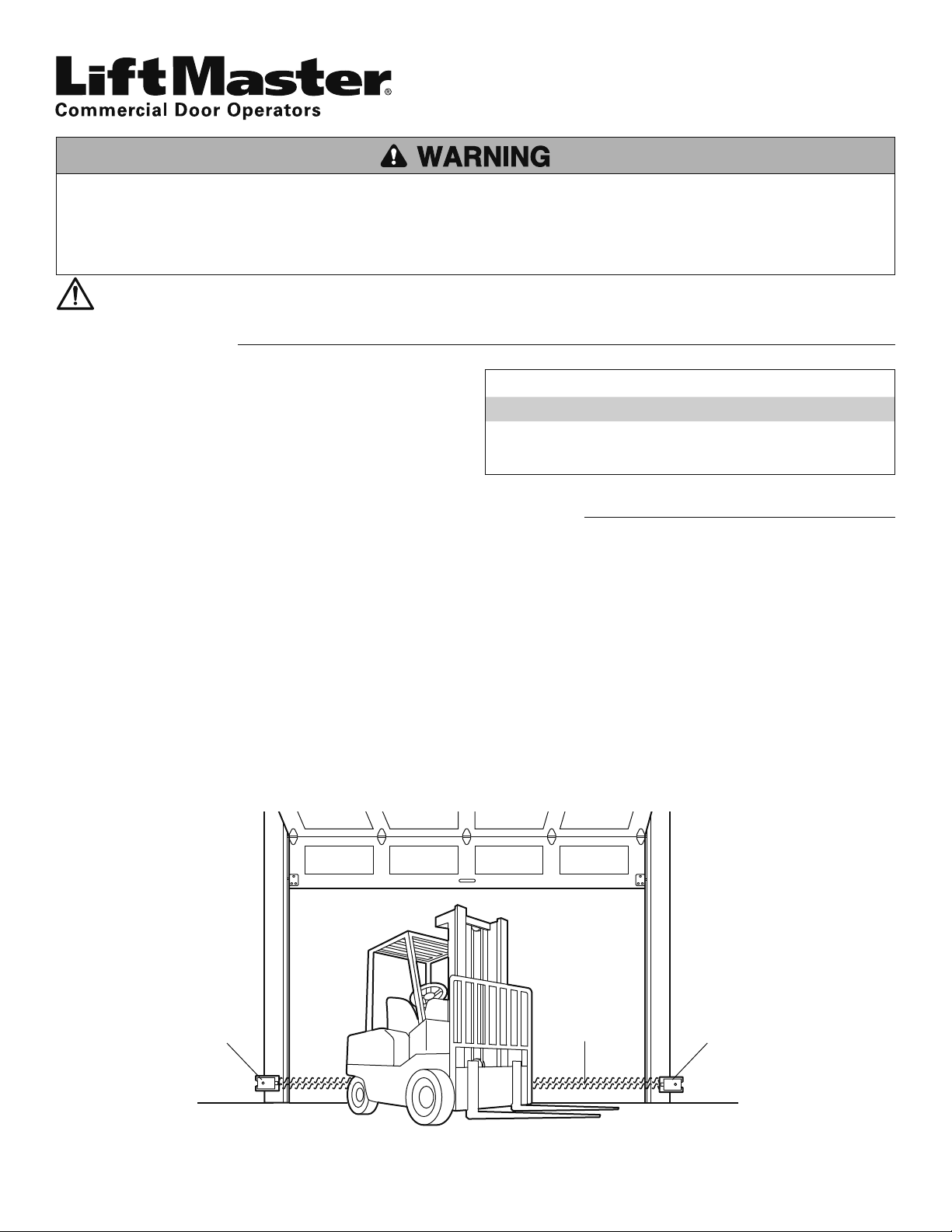
Facing the door from inside the garage (installation procedures are the same for all door types).
Left Side of Garage Right Side of Garage
Photoelectric Sensor
Photoelectric Sensor
Invisible Light Beam
Protection Area
THE COMMERCIAL PROTECTOR SYSTEM®
IMPORTANT INFORMATION ABOUT THE PHOTOELECTRIC SENSORS
Be sure power to the operator is disconnected.
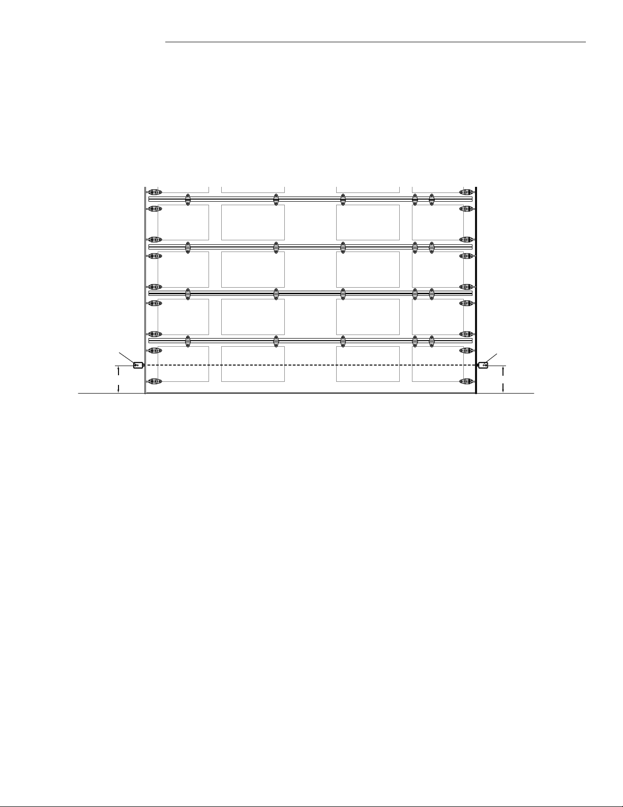
When properly connected and aligned, the photoelectric sensors will detect an obstruction in the path of its invisible light beam. If an
obstruction breaks the light beam while the door is closing, the door will stop and typically reverse to the full open position.
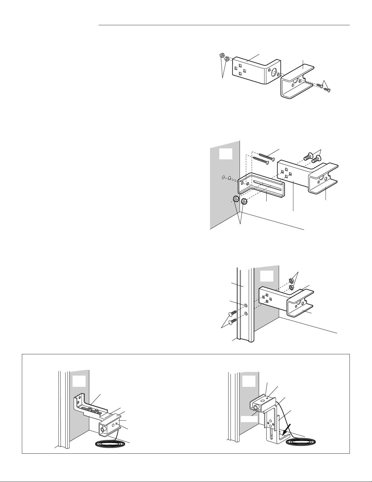
The photoelectric sensors must be installed inside the garage so that the sending and receiving sensors face each other across the door,
no more than 6" (15 cm) above the floor. Either can be installed on the left or right of the door as long as the sun never shines directly
into the receiving eye lens. This product is not suitable for outdoor use.
The brackets must be securely fastened to a solid surface such as the wall framing. If installing in masonry construction, add a piece of
wood at each location to avoid drilling extra holes in masonry if repositioning is necessary.
The invisible light beam path must be unobstructed. No part of the garage door (or door tracks, springs, hinges, rollers or other
hardware) may interrupt the beam while the door is closing. If it does, use a piece of wood to build out each sensor mounting location to
the minimum depth required for light beam clearance.
APPLICATION
The Commercial Protector System®(CPS) is suitable for LiftMaster
Commercial Door Operators with a Normally Open (N.O.) sensing
edge input.
The CPS is for use with ancillary entrapment protection devices
only, and not used for primary monitored entrapment protection
devices.
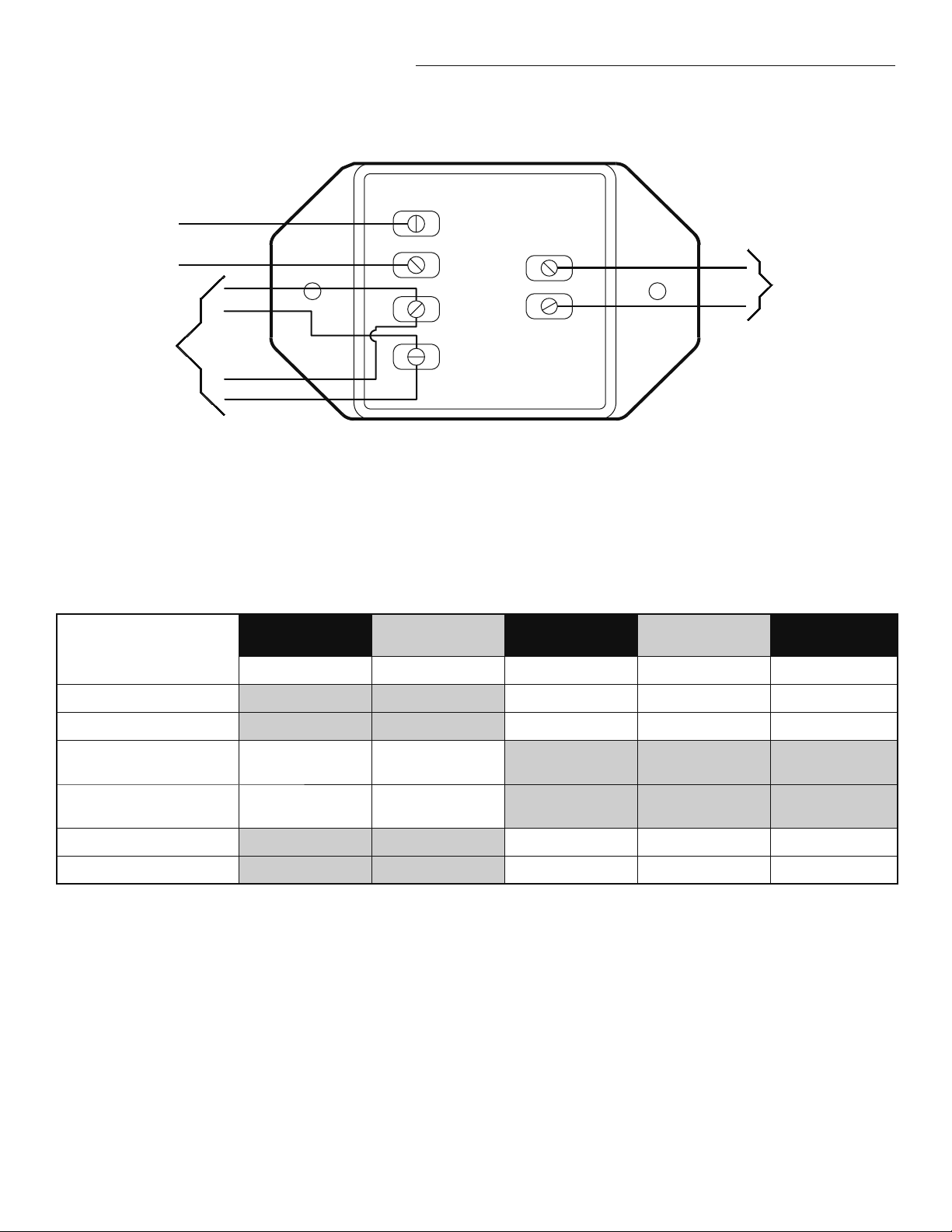
CARTON INVENTORY
PART # DESCRIPTION QTY
CPS-U Photoelectric Sensors with Mounting Hardware 1
41K4629 Commercial Protector Interface 1
WARNING: This product can expose you to chemicals including lead, which are known to the State of California to cause cancer or birth defects
or other reproductive harm. For more information go to www.P65Warnings.ca.gov