Aucma AWater 1 User manual
User's Manual
Reverse Osmosis
AWater 1
Model: ARS-500C1
Water Filtration System
www.aucmawater.com


This device complies with part 15 of the FCC Rules.
Operation is subject to the following two conditions:
(1) This device may not cause harmful interference,
and (2) this device must accept any interference re-
ceived, including interference that may cause unde-
sired operation. Any Changes or modifications not
expressly approved by the party responsible for
compliance could void the user's authority to operate
the equipment.

Contents
Installation Guides
Product Introduction···········································1
Parts List ··························································2
Inspect the Package ···········································3
Installation Tips··················································4
Installation Steps················································5
User's Manual
Display and Operation········································12
System Maintenance·········································16
Troubleshooting ··············································· 16
Step 1: Install the Feed Water Adapter ····································5
Step 2: Install the RO Faucet ·················································6
Step 3: Install the Drain Saddle··············································7
Step 4: Position the RO System Housing ··································7
Step 5: Connect Tubing·························································8
Step 6: Connect Power Cord ··················································9
Step 7: Install the Filters ······················································10
Step 8: Start up the System ····················································10
Section 1: Water Quality Display ············································12
Section 2: Filter Life Reminder ··············································12
Section 3: Filter Replacement Guide ······································14
Section 4: Automatic Flushing ·················································15
Installation Guides
Front Top
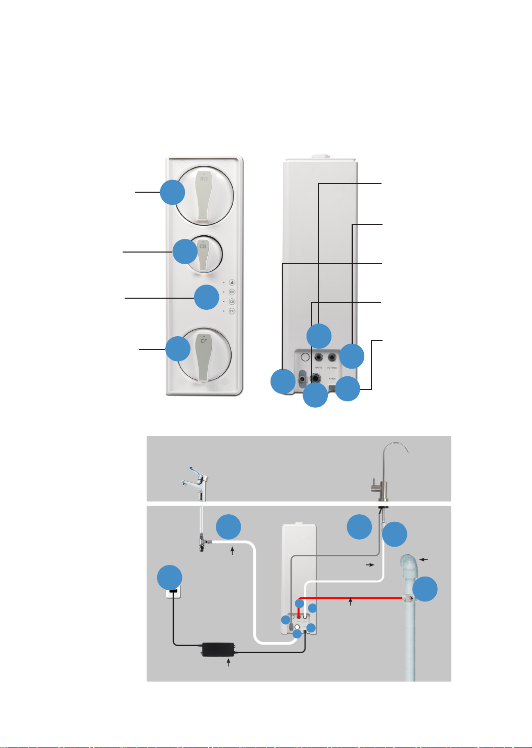
Product Introduction
A: Reverse Osmosis
Membrane Filter (RO)
E: "WASTE" Water Port
F: "FILTERED" Water Port
G: "FAUCET" Connector
H: "INPUT" Water Port
I: "POWER" Port
B: Activated Carbon
Filter(CB)
C: Filter Life & Water
Quality Indicators
D: Pre-sediment and
Carbon Block Filter (CF)
This is a brief introduction of various parts and sample connections. Please identify
and get familiar with these parts and connection points for a smooth installation.
A
B
C
DF
GHI
E
K
J L M
N
G
EF
HI
Sample Connection
J-H, From Feed Water Adapter to "INPUT" Water Port
M-F, From Faucet Quick-Connect Fitting to "FILTERED" Water Port
N-E, From Drain Saddle to "WASTE" Water Port
L-G, From Faucet Power Cord to "FAUCET’’ Connector
K-I, From "POWER" Port to Power Socket
Input Water Tubing
3/8” PE Tube
Power Adapter
Waste Water Tubing
1/4” PE Tube
Filtered Water Tubing
1/4” PE Tube Drain Pipe
1

Parts List
System Housing
X 1
RO Faucet
X 1
Drain Saddle 1/4”
X 1
White 1/4" PE Tubing
X 1(60")
Red 1/4" PE Tubing
X 1(60")
Power Adapter
X 1
Feed Water Adapter
3/8”-1/2”
X 1
White 3/8” PE Tubing
X 1(60”)
Lock Clip
X 5
Teflon Tape
X 1
Activated Carbon Filter
(CB: ARS-500C1-CB)
X 1
Pre-sediment and
Carbon Block Filter
(CF: ARS-500C1-CF)
X 1
Reverse Osmosis
Membrane Filter
(RO: ARS-500C1-RO)
X 1
2

Inspect the Package
After receiving the package, open the box and check if there is any thing left out or
damaged during shipping.
Sample Connection
Specifications
Model ARS-500C1
18.03” * 5.51” * 17.13”
14.5-87 PSI / 0.1-0.6 MPa
41-100 °F / 5–38 °C
Municipal Tap Water
500 GPD
Input 110~120V AC
Output 24V DC
RO System Size (L*W*H)
Feed Water Pressure
Feed Water Temperature
Feed Water Requirement
Daily Production Rate
Power Specification
·Variable speed drill
·Drill bit
·Adjustable wrench, pliers
·Screwdriver
·Utility knife or scissors
·Flashlight
·Towel
To achieve the optimal performance, it is highly recommended to use the system
within the operational parameters.
NOTE:
The Daily Production Rate is measured under 30 PSI dynamic feed water pressure
and 77 °F water temperature.
3
Installation Tips
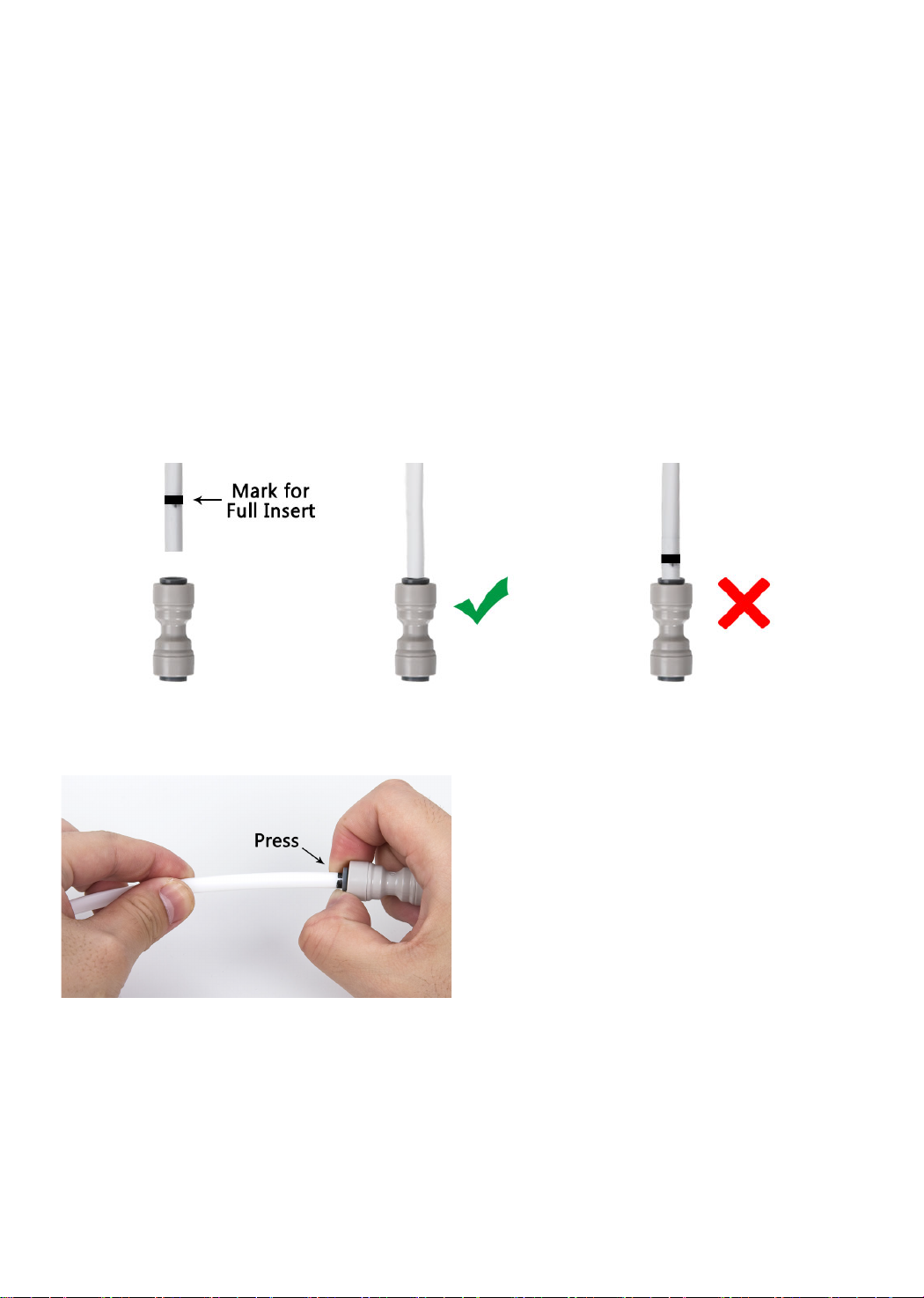
How to Use the Quick-Connect Fittings
Connection:
Please ensure that the tubing is fully inserted, or leakage will occur. The existing mark
(Figure 1) at the end of the tubing can help you to confirm if the tubing is fully inserted
into the fitting. Push the tubing into the fitting until you reach the mark on the tubing.
After fully inserted the tubing. Put the blue lock clip on the fitting and it will lock the
tubing in place.
DO NOT pull out the tubing directly. That will damage the fitting and cause leakage.
Remove the blue lock clip from the fitting.
Use your thumb and index finger to
press down the lock sleeve. Use your
other hand to pull out the tube from
the fitting.(Figure 2)
Figure 1
Figure 2
Disconnection:
4

Installation Steps
NOTE:
Step 1: Install the Feed Water Adapter (3/8" or 1/2")
The RO system must be connected to the COLD water supply ONLY.
Do not install the system in exposure to direct sunlight or harmful chemicals.
Do not install the system near any heat source.
Do not install the system outdoors.
NOTE:
If the cold water pipe is 1/2", unscrew the two converters from the feed water adapter (Figure 4), and
then implement step 3.
Twist the cold water pipe (with its washer) onto the feed water adapter and tighten with an adjustable
wrench.
The “INPUT" water tubing has been attached to the feed water adapter for easy installation.
1. Shut off the water supply. Turn on the kitchen faucet to release the water pressure;
2. Disconnect the cold water pipe from the cold water supply valve;
3. Twist the feed water adapter onto the cold water supply valve (with its washer) and
tighten it with an adjustable wrench (Figure 3);
Figure 3 Figure 4
5

Step 2: Install the RO Faucet (Non-Air Gap Faucet)
The RO system must be connected to the COLD water supply ONLY.
Do not install the system in exposure to direct sunlight or harmful chemicals.
Do not install the system near any heat source.
Do not install the system outdoors.
1. Insert the faucet spout into the faucet body;
2. Insert the faucet stem and power cord into the hole on the countertop;
3.Under the sink, put the mounting washer on the faucet stem, slip on the nut and tighten it up;
4.Insert the quick-connect fitting onto the faucet stem fully and firmly.
Figure 5
6

Step 3: Install the Drain Saddle
Step 4: Position the RO System Housing
1. Choose a spot on the drainpipe that is convenient for installing the drain saddle;
NOTE: It's recommended to install the drain saddle on vertical drainpipe
2.Punch a 1/4" hole on the drainpipe. Be sure not to penetrate the opposite side of the pipe(Figure 6);
3.Slip the front plate on one end of the tubing (without the mark), and insert the tubing into the punched
hole for about 0.6" (Figure 7);
4.Position the back plate on the drainpipe by tightening the screws and nuts evenly while leaving the
tubing in the hole;
5. Pop the lock clip on the fitting to secure the connection (Figure 8).
NOTE: In some cases, the "WASTE" water tubing needs to be connected to the drainpipe through air
gap. Consumers need to purchase air gap accessories additionally then.
Check if there is sufficient space under the countertop for assembling the system (18.03” * 5.51” *
17.13”). The front panel should be facing out, which will be convenient for future filter checking.
NOTE: It is not recommended to place the housing against the cabinet, vibrations may occur when the
system works.
a)The power-supply receptacle for the appliance shall be adjacent to the space in which the
appliance is installed;
b)There should be enough space between the compartments specified in (a) that can allow the attach-
ment plug to pass through. But the opening shall not be more than 1-1/2 in (38 mm);
Figure 6 Figure 7 Figure 8
7
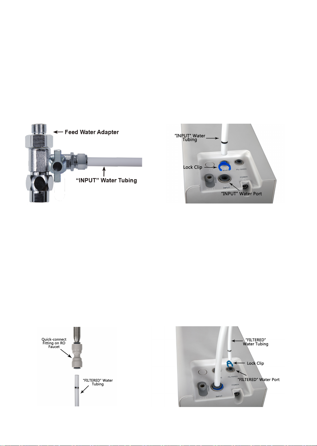
Step 5: Connect Tubing
1.Install the "INPUT" Water Tubing
·Remove the plug from "INPUT" water port;
·Identify the white 3/8" PE tubing which has been attached to the feed water adapter (Figure 9);
·Insert the other end of the tubing into the "INPUT" water port (Figure 10), and pop the lock
clip on the fitting.
NOTE: Make sure it is fully inserted until you reach the mark on the tubing.
2.Install the "FILTERED" Water Tubing
·Remove the plug from the "FILTERED" water port;
·Identify the white 1/4" PE tubing;
·Insert one end of the PE tubing into the quick-connect fitting on the RO faucet (Figure 11), and pop in
the lock clip on the fitting;
NOTE: Make sure it is fully inserted until you reach the mark on the tubing.
·Insert the other end of the tubing into the "FILTERED" water port (Figure 12), and pop the lock clip on
the fitting.
NOTE: Make sure it is fully inserted until you reach the mark on the tubing
Figure 9
Figure 11 Figure 12
Figure 10
8
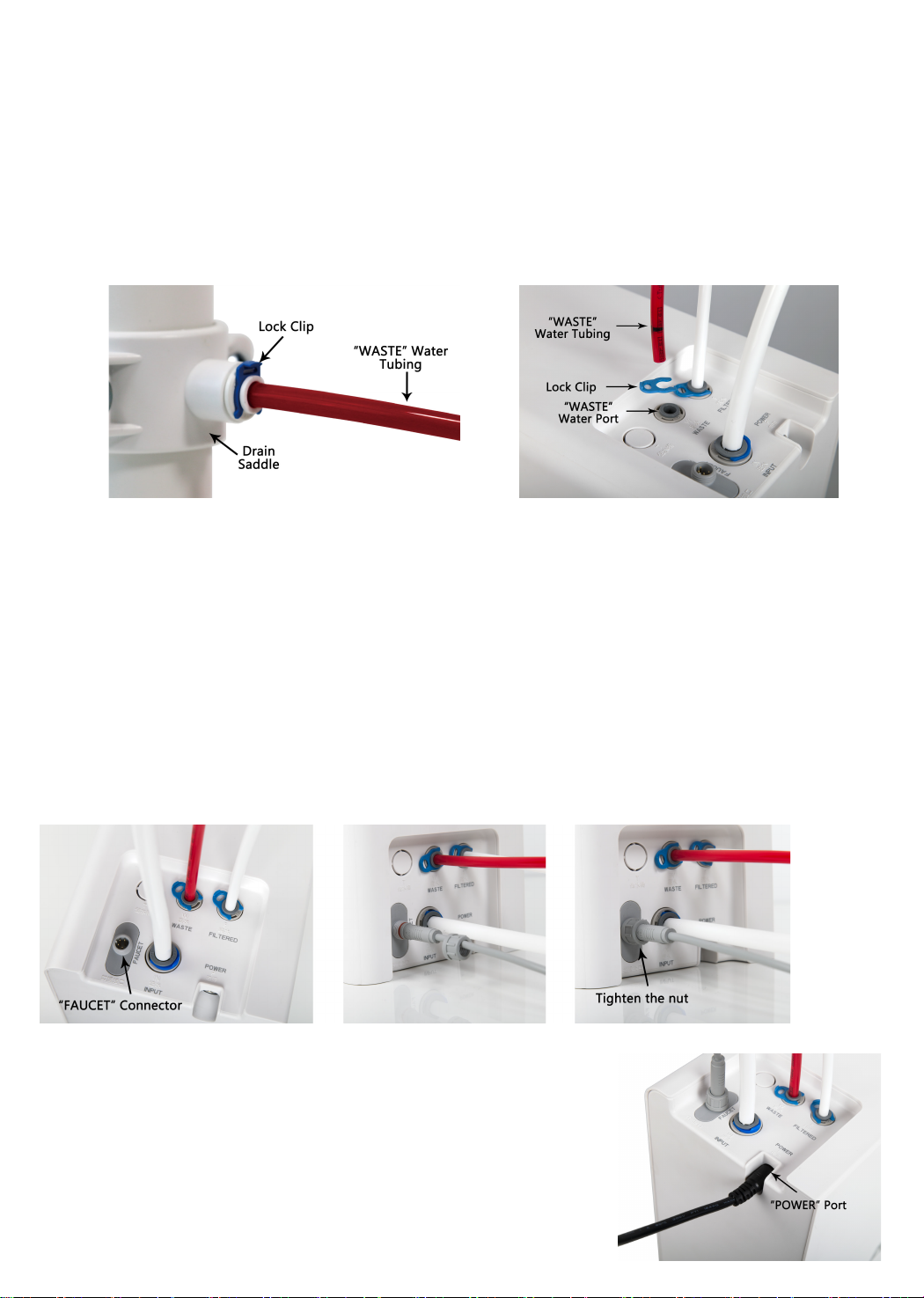
Step 6: Connect Power Cord
Connect the RO faucet to the system: Insert the power cord which is attached to the RO faucet into the
"FAUCET" connector (Figure 15) at the back of the housing, and tighten the nut.
Connect Power Adapter: Insert the DC head of the power adapter into the "POWER" port at the back of
the housing (Figure 16).
NOTE: Please do not connect power socket now.
3.Install the "WASTE" Water Tubing
·Remove the plug from the "WASTE" water port;
·Identify the red 1/4" PE tubing which has been attached to the drain saddle (Figure 13);
·Insert the other end of the tubing into the "WASTE" water port (Figure 14), and pop the lock clip onto
the fitting.
NOTE: Make sure it is fully inserted until you reach the mark on the tubing.
Figure 13
Figure 15
Figure 14
Figure 16
9

Step 7: Install the Filters
Each filter is marked with a logo (CB/CF/RO) and an installation arrow.
1. Insert the filter into its corresponding hole (Figure 17), align the arrow with the empty circle on the
housing (Figure 18);
2. Twist the filter with a little force forward in a clockwise direction for 90 degrees, until the arrow is
aligned with the solid circle on the housing (Figure 19);
3. Repeat the above steps to install the other two filters.
Step 8: Start up the System
1.Turn on the cold water supply valve. Check for leaks;
2.Insert the plug of power adapter into the socket;
NOTE: If the system can't be powered on after you insert the plug of power adapter, check the power
under the sink, check the connection between the plug and the power outlet, and ensure that the system
has been plugged correctly into the power outlet. To test if there is a problem with the system itself, just
pick up the system and try another power outlet.
Please contact us if the system can't be powered on. We will help you figure it out.
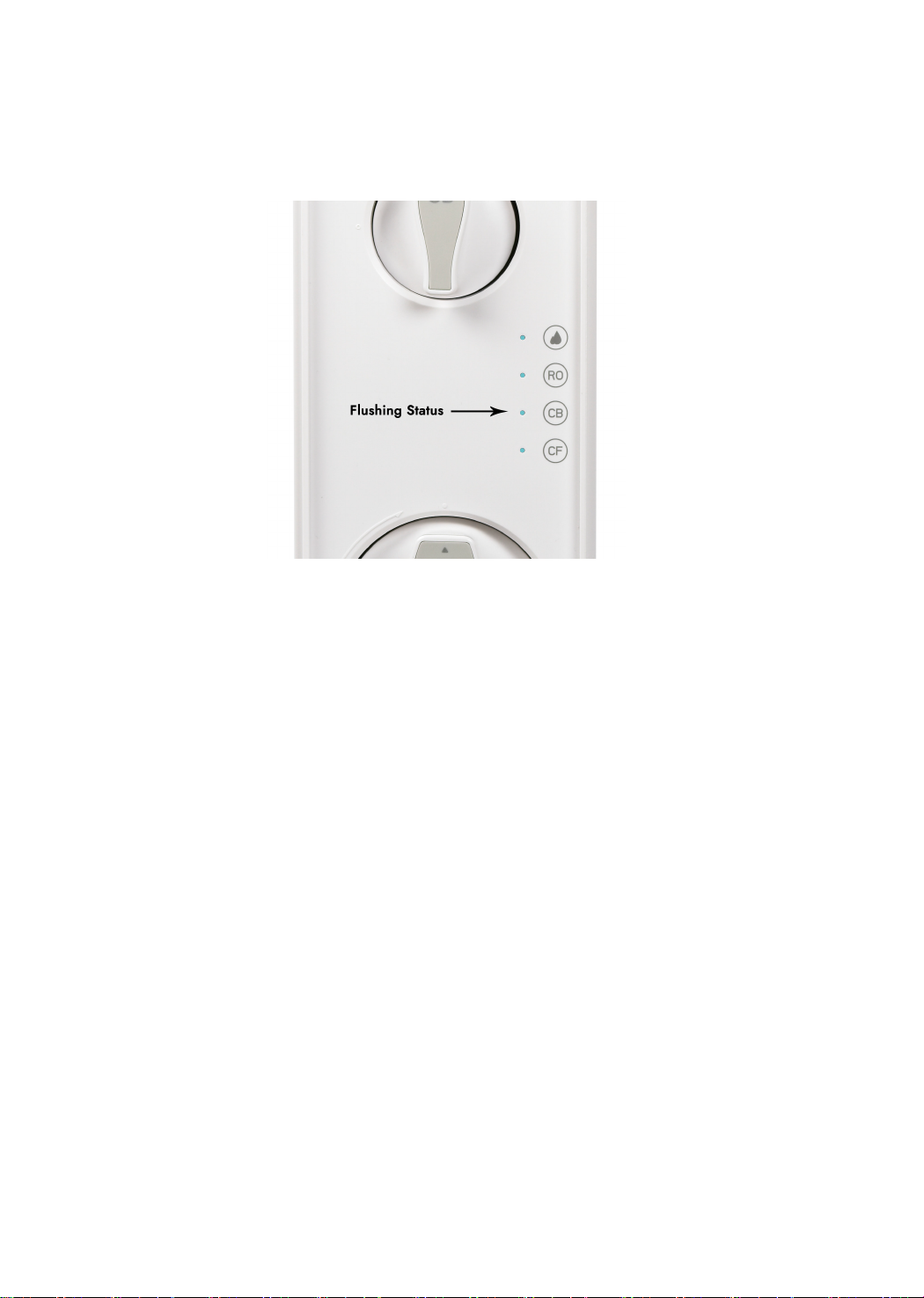
3.The system starts flushing automatically for 5 minutes;
NOTE: There will be one beep. The filter life indicators will flash blue, purple and red in turn and then
turn blue for 5 minutes (Figure 20). Do not turn on the RO faucet. Allow the system to flush automatically
for 5 minutes. The three indicator lights will be off when the flush is finished.
A slow water flow is normal if the RO faucet is turned on, and water is not drinkable during the automatic
flush.
4.Turn on the RO faucet, and allow it to run for 30 minutes, and then it can be used normally.
NOTE: Be sure to carefully check the tightness of each part of the system while flushing. Check and
ensure all tubing is installed correctly and completely. Make sure there are no leaks at the joints,
fittings, valves and tubing connections.
Figure 17 Figure 18 Figure 19
10
NOTE: The water is not drinkable during the flushing. The 30 minutes are accumulative. If the flush is
stopped in advance, the system will continue to flush when you open the RO faucet again until it reaches
30 minutes.
5. Confirm the flush is completed before turning off the RO faucet and ensure it's not leaking.
* Please note that the reading in the figure is only used as an example, and the actual reading may vary
according to different water conditions.
Figure 20
11
Display and Operation
User's Manual
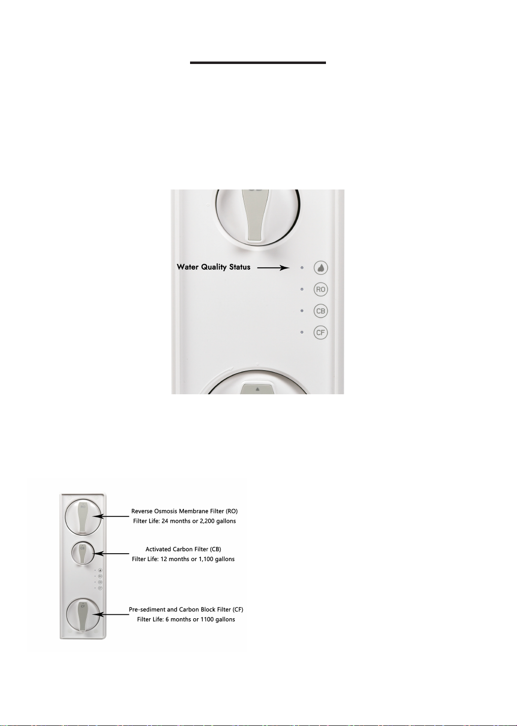
Section 1: Water Quality Display
Section 2: Filter Life Reminder
The built-in TDS sensor is used to test the water quality when the system starts working,
and shows the water quality status on the front panel (Figure 21).
Figure 22
NOTE: Filter life may vary depending on water
quality and usage.
Please be reminded to replace the filter accord-
ing to the filter life indicators.
Figure 21
12

Status Remaining
Life (Day) Remaining Capacity (G)
Indication
Light Buzzer
Blue N/A
Purple Beeps 2 times when
dispensing water
Red Keeps beeping when
dispensing water
Status
Good
Replace Soon
Replace Now
>15 >40
≤15 ≤40
≤0 ≤0
Normal
Pre-warning
Warning
Display Status:
1. Filter Life Indicator on System Housing
The electronic filter indicators (CF/CB/RO) on the front panel (Figure 23) will notify you to change
filter by color change. Be sure to reset the filter life indicator after replacing the filter.
Display Time:
·All indicators will go off 5 minutes after the system stops.
·Check the filter life status by touching the indicators, and the lights will go off in 30 seconds.
Different colors of light will be displayed on the faucet based on different filter life status (Figure 24).
2. Filter Life Indicator on the RO Faucet
Figure 23
NOTE: The indicators will notify you according to using time or filter capacity, whichever comes first.
Figure 24
13
Light
Blue
Purple
Red
Blue Flash
Red Flash
Remaining Life (Day)
>15
≤15
≤0
/
/
Remaining Capacity (G)
>40
≤40
≤0
/
/
Status
Good
Replace Soon
Replace Now
Flushing
Malfunction
NOTE: If the filter expires, please replace the filter immediately.
Otherwise, the filtration efficiency will decrease greatly and affect performance.
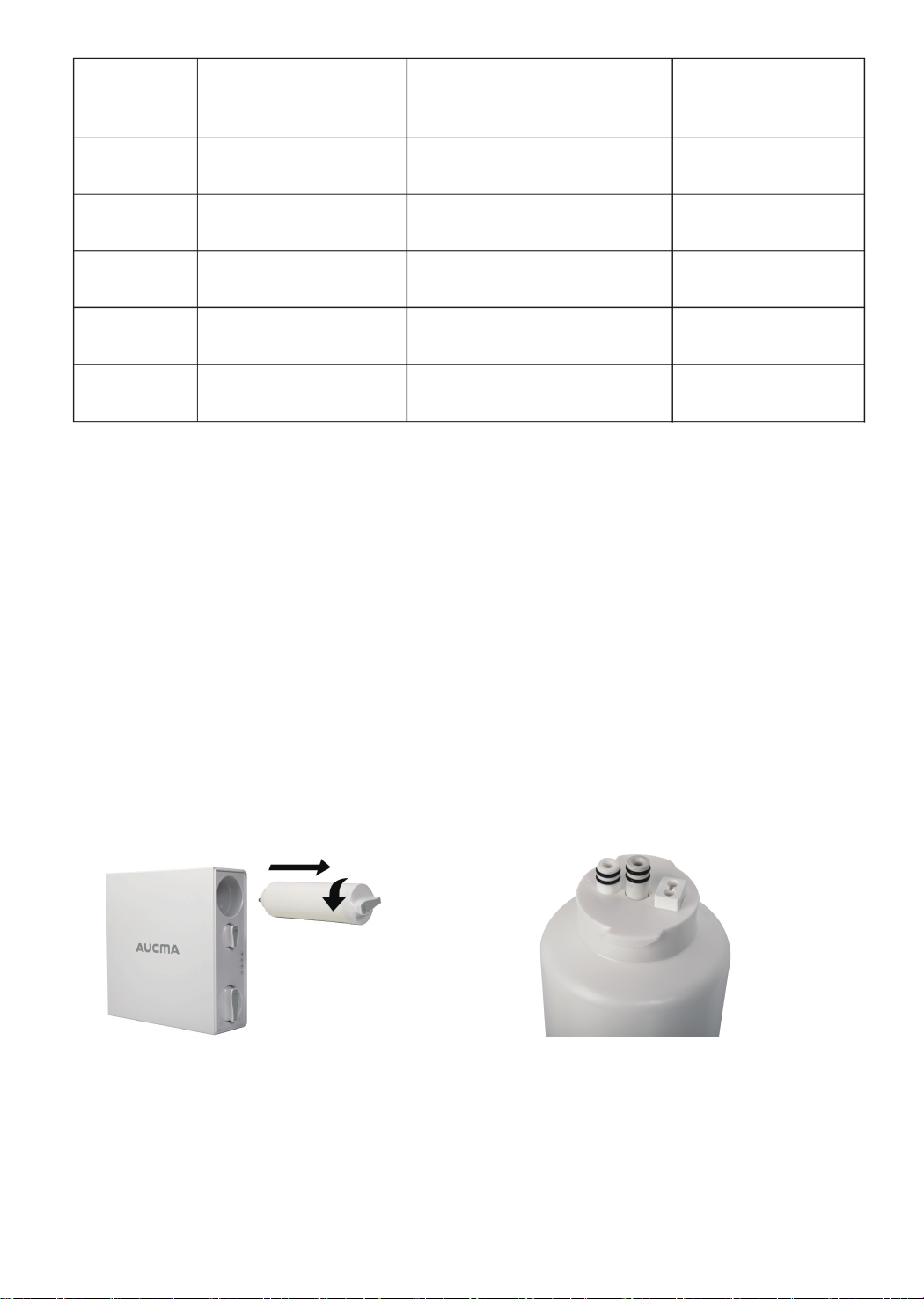
How to Replace Filters:
The filters could be replaced without cutting off power or water supplies, and there will be no
water and electric leakage.
1. Rotate the filter that needs to be replaced in a counterclockwise direction (Figure 25).
NOTE: After replacing the CF and CB filter, it's recommended to press the center knob
(Figure 26) at top of the old filter to release the pressure in it to avoid water spills.
A towel or bucket will be needed to catch any excess water;
2. Rotate the new filter in a clockwise direction into the housing;
3. Reset the filter life indicator and flush the filter after replacement.
Press and hold the CB filter life indicator for 7 seconds until the system beeps.
Section 3: Filter Replacement Guide
How to Reset the Filter Life Indicator (Taking Reset of CB Filter
Life Indicator as an Example):
Figure 25 Figure 26
14

How to Flush the Filter after Replacement:
NOTE: The screen will show the flushing status.
CF filter: It will be flushed automatically for 5 minutes without turning on the RO faucet;
CB filter: Turn on the RO faucet to flush for 15 minutes;
RO membrane filter: Turn on the RO faucet to flush for 30 minutes.
Section 4: Automatic Flushing
The system will be automatically flushed under the following circumstances:
Flush for Accumulative Working Time over 2 Hours:
To maintain and extend the life expectancy of the filters, the system will be automati-
cally flushed for 20 seconds when it continually works more than 2 hours, the front panel
will show as in Figure 20. If the user takes water during flushing, the system will stop
flushing and start dispensing.
Flush for No Working within 24 Hours (Holiday Mode):
In order to ensure the drinking water is fresh and healthy, the system will be automati-
cally flushed for 1 minute when there is no water dispensing for 24 hours.The front panel
will display as Figure 20. If taking water during flushing, the system will stop flushing
and start dispensing.
Flush for Power Restore
When power is restored from a blackout, the system will be forced to flush automatically
for 20 seconds, and the front panel will display as Figure 20. The lights will flash in turn
for one second, and then the blue light will be on for 20 seconds. The lights will be off
when the flushing is finished.
15

System Maintenance
Troubleshooting
·If you are not going to use the system for more than one week, turn off the RO faucet, shut off the cold
water valve, and disconnect the power. Seal the filters and store them in the refrigerator (not the
freezer). Before using the appliance again, you need to open the RO faucet and allow it to run for 10
minutes first. Otherwise, the filters need to be changed, as bacteria may grow when the system is not
used for such a long time.
·Please replace the filter regularly according to the filter life indicator.
·NOTE: Actual performance may vary depending on the water quality and usage. In case of blockage or
failure of the filters, it's recommended to replace the filters according to actual situations.
·Clean the system with clear water. Do not spray the water directly. Do not use abrasive cleaner or
corrosive liquid to clean.
·Keep the waste water pipe unobstructed to avoid damage to the filter or internal parts.
·When the drainpipe is blocked, do not use the system to avoid waste water from soaking the floor, and
turn off the system power.
·Check the system and water pipe fittings regularly to avoid any property damage.
·Regularly check whether the power supply and wires are damaged or loose to avoid major accidents
caused by electric leakage.
a. Check the power under the sink, as this mostly occurs when the power under the sink is off. Also,
check the connection between the plug and the power outlet, and ensure that the system has been
plugged correctly into the power outlet, as this may occur in a few cases. To test if there is any problem
with the system itself, just try another power outlet. Or you can contact us if the system can't be pow-
ered on. We will help you to figure it out.
·If the System Cannot Be Powered on AfterYou Insert the Plug of Power
Adapter
a. Filter expired. Check the filter life indicators to confirm if the filters need to be replaced and replace
them at once.
b. Low water pressure. Check and confirm if the water pressure is between 14.5 PS and 87 PSI.
c. Water supply is off. Turn on the feed water adapter or water supply valve.
d. Incorrect filter installation. Re-install the three filters, and make sure they are fitted.
e. A tubing is bent. Check all tubings and remove any bent one.
·No Water comes out from RO Faucet
16
This manual suits for next models
1
Table of contents
Other Aucma Water Filtration System manuals

Popular Water Filtration System manuals by other brands

EHEIM
EHEIM eXperience 250 manual

Watts
Watts SmartStream UV WB002 Installation, operation and maintenance manual

Quooker
Quooker ST-VAQ installation guide

Aquatop
Aquatop ELIMINATOR IF7-UV owner's manual

TAISEI KOGYO
TAISEI KOGYO TM instruction manual

Novy
Novy novy 7941400 Installation and operating instructions


