Geyser NANOTECH User manual

WATER PURIFICATION SYSTEM ON
THE BASIS OF THE NANOFILTRATION
GEYSER
NANOTECH MANUAL
for installation and operation of a
HOUSEHOLD FILTER
12 l
MODIFICATIONS
GEYSER-NANOTECH
GEYSER-NANOTECH P


TABLE OF CONTENTS:
Geyser technologies ...................................................................................... 4
Purpose ......................................................................................................... 4
Filtering materials and cartridges.................................................................. 4
Requirements to the source water ................................................................. 5
Technical characteristics............................................................................... 5
Electrical scheme .......................................................................................... 5
Connection diagrams and a scope of delivery of............................................ 6
System installation........................................................................................ 8
System flush ............................................................................................... 10
System maintenance ....................................................................................11
List of possible failures and methods of their elimination ............................12
Warranty liabilities........................................................................................14
Thank you for choosing Geyser water lter!
Our developments and technologies allow providing with the water perfect quality
in your house.
All functionality capabilities, an also a method of installation of the water
purication system Geyser are described in this manual. Please read it carefully and
retain for future reference.
The water purier set includes all parts required for using immediately after the
installation.

4
GEYSER TECHNOLOGIES
Safety – the system is checked for durability with the pressure of 25 atm.
Efciency – removal of all objectionable admixtures.
Ecological compatibility – all elements of the system are certied for contact with the
drinkable water.
Utility – preservation of the water natural mineral composition.
COMPARISON OF THE DEGREE OF PURIFICATION
OF THE NANOFILTRATION AND REVERSE-OSMOTIC MEMBRANES
Purication type Microorganisms Iron, heavy metals Reduction in hardness
Nanoltration NF
(Geyser-Nanotech) + + 75-80%
Reversed osmosis RO
(Geyser-Prestige) + + 95-98%
Data in the table show that the water additional mineralization is not required after the
nanoltration purication.
Advantages of the nanoltration:
reduction in the hardness, preservation of the mineral composition
the reagentless disinfection of the water
reduction of the drain flux twofold
environmentally-friendly preservation method
PURPOSE
Geyser-Nanotech lter is used for the deep purication of the tap water by the reverse
osmosis from mechanical admixtures, chloride and organic compounds, carbolic acids,
bacteria and viruses. The system decreases the water hardness, removes foreign flavour,
smell and color.
FILTERING MATERIALS AND CARTRIDGES
The treatment unit consisting of 3 cartridges for increase of the nanoltration membrane
operating life:
The polypropylene cartridge with the porosity of 5 µm removes suspended solids and ne
insoluble impurities. The cartridge volume is up to 7,000 l.
The cartridge of BAF series contains a multicomponent media on the basis of sorbents
and ion-exchange materials, which removes organic impurities and chloride, decreases a
content of iron and heavy metals that signicantly increases the membrane life. The life
is up to 12,000 l.
The cartridge of CBC series contains the high quality activated coconut carbon (Thailand)
processed in accordance with the carbon-block technology for the removal from the
water of the residual chlorine and organochloride admixtures. The life is up to 7,000 l.
The nanoltration membrane performs the main purication from dissolved impurities,
heavy metals, microorganisms and reduces a content of hardness salts. The life is up to
3,500 l.
The post carbon cartridge for water conditioning. The life is up to 6,000 l.

5
REQUIREMENTS TO THE SOURCE WATER
ATTENTION! The reverse osmosis system performance directly depends on a pressure in a
water conduit. If a pressure in your water conduit is less than 3atm., that it is necessary to
complement the reverse osmosis system with the booster pump.
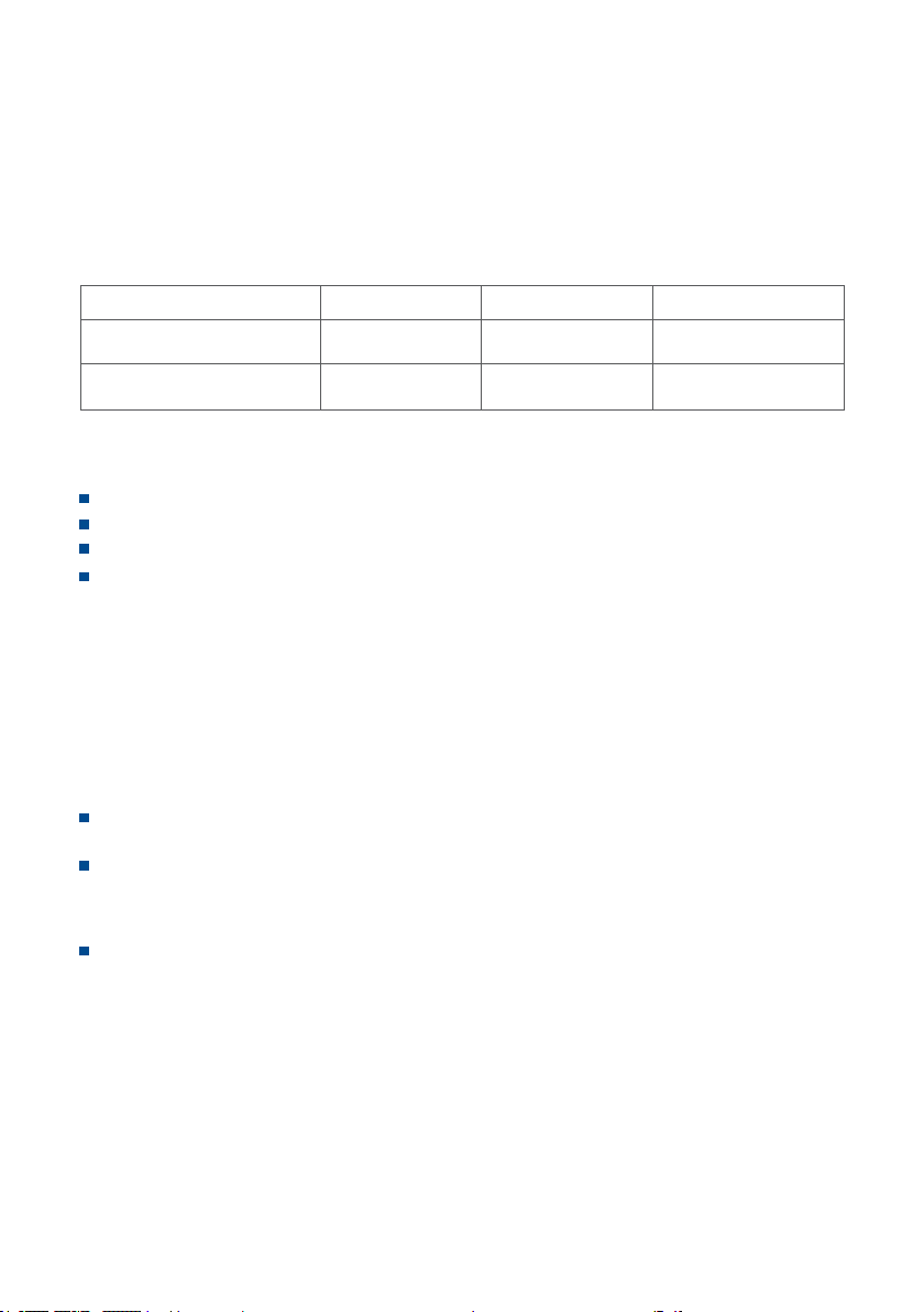
The water pressure at the inlet of the system with a pump, atm. 2-8
The water pressure at the inlet of the system without a pump,
atm. 3-8
pH 3-11
Water temperature, °С +4...+40
Mineralization, mg/l no more than 1,500
Summary concentration of chlorides, mg/l no more than 1,200
Turbidity, mg/l no more than 1
Hardness, mg-equ/l no more than 7
Iron (Fe2+), mg/l no more than 0.3
Iron (Fe3+), mg/l no more than 0.3
Manganese (Mn), mg/l no more than 0.1
Nitrates, mg/l no more than 45
Permanganate oxygen consumed, mg О2/l no more than 10
Total microbial number, CFU/ml no more than 1,000
Coli-index 1
Higher values of indicators require the additional preliminary purication.
TECHNICAL CHARACTERISTICS
ATTENTION! If characteristics of the source water do not comply with the specied
requirements, that the operating life of the membrane and replaceable ltering modules can
be smaller than the operating life stated in this manual.
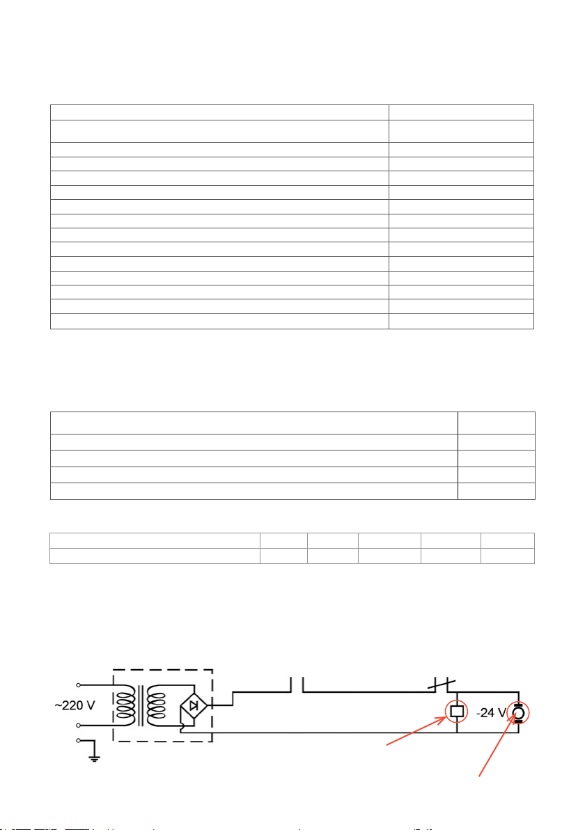
The storage tank volume (water volume in the storage tank is up to 70%* of its
volume), l 8; 12; 16
Excessive air pressure in the storage tank, atm. 0.4-0.5
Performance (depends on the water pressure and temperature, see appendix 1), l/day up to 200
Temperature of the puried water, °С +4...+40
Dimensions (without the storage tank), mm 470*380*420
* at a pressure in the water main of 5 atm.
ADJUSTMENT TEMPERATURE COEFFICIENT*
TEMPERATURE 5 10 20 30 40
ADJUSTMENT COEFFICIENT 2,16 1,702 1,205 0,974 0,771
The membrane actual performance = the membrane performance stated in the table of technical
characteristics/the adjustment coefcient
* According to the data of the manufacturer of membranes Vontron Membrane Technology Co., Ltd.
Low pressure
controller
Power supply unit
Solenoid valve
Pump electric motor
High pressure
controller
ELECTRICAL SCHEME OF THE REVERSE OSMOSIS SYSTEM FOR MODELS
WITH THE PUMP

6
1. Cases with lter elements ......................................................................... 1 set
I – a case of the mechanical lter
II – a case of the cartridge of BAF series
III – a case of the carbon lter
IV – a case of the nanomembrane
V – a case of the carbon post-lter
2. A gate of the storage tank.......................................................................... 1 unit
3. Storage tank** ............................................................................................ 1 unit
4. Tap of clean water ...................................................................................... 1 set
5. Drain flux limiter ......................................................................................... 1 unit
6. Reverse-flow valve ..................................................................................... 1 unit
7. Automatic water switch ............................................................................. 1 unit
8. Drain strap .................................................................................................. 1 set
9. Tee (adapter) with the water feed tap ....................................................... 1 set
10. Pipe 1/4’’ ......................................................................................................1 set.
*The manufacturer reserves the right make small improvements of the system design and
conguration without their reflection in this manual.
** Variants of the conguration with the storage capacity of 8; 12; 16 liters are available.
CONNECTION DIAGRAMS AND A SCOPE OF DELIVERY OF
GEYSER-NANOTECH

7
CONNECTION DIAGRAMS AND A SCOPE OF DELIVERY OF GEYSER-
NANOTECH P
(WITH PUMP)
1. Cases with lter elements .......................................................................... 1 set
I – a case of the mechanical lter
II – a case of the cartridge of BAF series
III – a case of the carbon lter
IV – a case of the nanomembrane
V – a case of the carbon post-lter
2. A gate of the storage tank .......................................................................... 1 unit
3. Storage tank**............................................................................................. 1 unit
4. Tap of clean water....................................................................................... 1 set
5. Drain flux limiter.......................................................................................... 1 unit
6. Reverse-flow valve...................................................................................... 1 unit
7. High pressure controller............................................................................. 1 unit
8. Drain strap................................................................................................... 1 set
9. Tee (adapter) with the water feed tap........................................................ 1 set
10. Pipe 1/4’’......................................................................................................1 set
11. Low pressure controller.............................................................................. 1 unit
12. Solenoid valve ............................................................................................. 1 unit
13. Pump ........................................................................................................... 1 unit.
*The manufacturer reserves the right make small improvements of the system structure and
conguration without their reflection in this manual.
** Variants of the conguration with the storage capacity of 8; 12; 16 liters are available.

8
SYSTEM INSTALLATION
We recommend carry out the system installation with
specialists or install it strictly in accordance with the
manual.
It is not recommended to disassemble factory
connections – the system is supplied in the assembled
condition and is tested for sealness with the high
pressure.
Remove the lter from its packing box. Remove
transport plugs (!).
Install the bracket with cases (and cartridges) at
a vantage place at a height of no less than 15 cm from
cases bottom to the floor.
The system and storage tank should be installed at a distance of no less than 1 meter
from heaters.
Connection to the water conduit
The system is connected to the COLD water main line.
Make sure that the water feed to the connection point is shut off!
1. Install the tee-adapter (A) on the cold water main line and seal joints (Fig.1).
!
CONNECTION
RECOMMENDATIONS FOR CONNECTION AND OPERATION
the connection is carried out only by the qualied specialist or the manufacturer’s
representative;
strictly follow the manual in case of individual connection;
all lter cases were tested for sealness and hydraulic impact, that is why there is on water
inside cases of the lter;
it is not recommended to disassemble factory connections without the need.
PREPARATION TO THE CONNECTION
1. Shut off the cold water feed to the connection point (Fig.1)
and discharge a pressure by opening the mixer.
2. Make sure that the lter flasks are reliably tightened*.
Tighten them, if necessary..
1
*Periodically check a reliability of the lter flasks tightness and
tighten them, if necessary.
Attention! A position of the vertical label, which is placed strictly
align the lter front center, does not guarantee the connection
leakproofness. A position of the label can be changed during
tightening of the flask screwed connection.
31
А
2
В

9
Drain strap installation
It is recommended to install a strap on the drain line 40 mm in diameter after the
syphon.
Drill a hole 7 mm in diameter at the place, where you plan to install the strap. If the drain
line is positioned horizontally, drill a hole on the pipe top part so that to avoid the waste
water penetration to the lter.
Remove a protecting lm from the sealing gasket.
23
Д
1
Г
The storage tank assembly
Remove the tank from the package. Install the tank on the support in such position, in
which the tank is more stable.
Screw a gate of the storage tank on the threaded tting (Fig.5).
Use the FUM tape for sealing connections.
Put a cap nut on the blue tube, insert a plastic grommet into the tube against stop and
screw a nut on the storage tank gate tting.
Insert a loose end of the tube to the carbon post-lter tee against stop.
Glue the gasket (D) from the strap inner side aligning simultaneously a hole in the gasket
and a hole in the strap tting (Fig.1).
Lock the strap (E) rmly on the drain line using screws aligning simultaneously holes of
the tting and the drain line (Fig.2). It is required to tighten xing screws uniformly (without
misalignment) so that both parts of the strap are placed in parallel.
Insert the red tube from the drain flux limiter (item 5, see the Connection diagram) into
the drilled hole for a length of 7-10 mm through the strap (E) (Fig.3).
56
4
2. Insert a plastic tube into a nut (C) (Fig.2). Insert the pipe into the ball tap tting against
stop and tightly screw a nut (Fig.3).
A loose end of this tube is connected to the lter input or to the low pressure controller tee
(for models with the pump) (Fig.4).

10
SYSTEM FLUSH
Turn off the storage tank tap, open the tap of clean water and water feed tap. Water will begin
to drop from the tap of clean water in 3-5 minutes. Leave the tap of clean water opened for 10
minutes, then close it and open the tank tap for several hours. A pressure will be generated in
the tank.
ATTENTION! Do not drink the water obtained during the rst tank lling. Open the tank with
clean water after the tank lling, drain the WHOLE tank and rell it as described above. This
will take several hours depending on a pressure in the supply main. After this the water can
be drunk. The system flush is required:
- after long (2 weeks) interruptions of usage;
- after maintenance (for example, replacement of cartridges)
Assemble the tap in the following order:
1. Faucet
2. Cuvette
3. Rubber gasket
4. Plastic washer
5. Metal washer
6. engraving washer
Fix the faucet on the sink. In the nut (E) pull up blue (Fig.
1). The piston (G) insert the inside tube until it stops. Slip
into the end of the tube resistant plastic ring (S) (Fig. 2).
Screw on the threaded stem of the valve nut (Fig. 3).
32
1
Connection of the tap of clean water
Drill a hole 12 mm in diameter in the washer.
6
2
4
1
5
3
6
S
Е
G

11
2 31
SYSTEM MAINTENANCE
Replacement of cartridges of I, II, III stage
Turn the water off at the input and in the storage tank. Open the tank with clean water
to release a pressure in the system. Remove the case flask using a wrench (I, II, III stages)
and replace the corresponding cartridge. It is recommended to grease a sealing ring with
the silicone lubricant or petroleum jelly before reinstallation (do not confuse with a sealing
agent!). Install the flask into position and tighten with a wrench. Check the system for the
sealness.
Before using flash the preliminary purication system. For this purpose detach the tube
from the membrane case and intercept the flow of water. Wait for the effluent water to be
clean and assemble the lter in the inverse order.
Membrane replacement
The membrane is delivered vacuum-sealed for its preservation during transportation and
storage. Before installation remove the package, shut off a tap of the tank and the water feed
tap, open the tap of clean water and detach tubes of the VI case connection (1). Withdraw the
old membrane (2). Install the new membrane and grease seals with the food grade silicone
or petroleum jelly (3). Screw the membrane case cap. Use only recommended membranes
for the replacement.
Replacement of the carbon post-lter
Detach tubes from the case (g..1), replace the post-lter with the new one, connect
tubes.
Note. Do not confuse the water input and output on the post-lter. The water flow
direction is indicated by the arrow on the post-lter case.
It is recommended to shut off the source water feed, disconnect the system from the
power supply and drain the puried water from the storage tank in case of a long (more than
1 week) interruption of the system usage.

12
LIST OF POSSIBLE FAILURES AND METHODS OF THEIR ELIMINATION
POTENTIAL
FAILURE REASONS ELIMINATION
METHOD NOTE
The white water
flows from the
tap of clean
water
There is the air in the
system
The air will
gradually be out of
the system
This situation is considered
normal during the new
system commissioning or
the replacement of ltering
modules
The water does
not flow from the
tap or flows very
slowly
The system has just
started to operate Wait for 4-6 hours
The tank lling can be from
4 hours depending on the
water temperature and the
pressure in the main.
The carbon post-lter has
exhausted its resource Replace the post-
lter Contact the customer
service
There is no the excessive
air pressure in the storage
tank
Pressurize the
membrane tank to
0.5 atm.
Contact the customer
service
The water does
not inflow to the
storage tank or
inflows slowly.
Noise, knock of
the pump
Low pressure in the supply
main (less than 3 atm.)
Install the facility
increasing a
pressure
The water intake speed to
the storage tank (after the
membrane) should be 75-
100 ml/min
The resource of
replaceable elements
of the water preliminary
purication is used up
Replace
Cartridges can be quickly
clogged due to a large-
scale waste dumping to the
water conduit or because
the water is constantly
flows through them, i. e. a
drain flux is not shut
The reverse-osmosis
membrane resource is
used up Replace
The membrane can be
clogged sufciently quickly,
if it operates on the hard
water
The automatic switch is
malfunctioning Replace Contact the customer
service
Obstructions in pipes Check and
eliminate
The storage tank gate is
closed Open
The tap at the lter input
is closed Open
The pump is
malfunctioning Replace A pressure behind the
working pump should not
be more than 7 atm.
The reverse-flow valve is
malfunctioning Replace Contact the customer
service
The high pressure
controller is
malfunctioning Replace Contact the customer
service
There is no contact in
electrical connections Check electrical
connections
Water leak Fittings are not tightened Tighten
connections

13
There is too little
water outflowing from
the storage tank
The system has just started
to operate
The tank lling can be
from 4 hours to 6 hours
depending on the water
temperature and the
pressure in the main
The excessive pressure is
low in the storage tank Increase the
pressure
The normal pressure in
the empty tank should
be 0.4-0.5 atm.
The storage tank is
full, but the water
flows to the drainage
The pressure in the supply
main is reduced, and, as a
consequence, the automatic
switch does not operate
Install the facility
increasing a
pressure
The automatic switch
steadily operates at the
pressure of more than
2.5 atm.
The automatic switch is
malfunctioning Replace The automatic switch
cannot operate due to a
production defect
Water has taste or
foul smell
Water stagnation in the lter
or the storage tank for a
long time
Wash the system
with water and
rell the tank
The carbon post-lter has
exhausted its resource Replace
Remainder of a preservative
agent in the storage tank
Drain water from
the tank and
rell it
The drain flux is not
shut after lling of the
storage capacity
The pressure in the supply
main is reduced, and, as a
consequence, the automatic
switch does not operate
Install the
pressure
increase
unit
The automatic switch
steadily operates at the
pressure of more than
2.5 atm.
The automatic switch is
malfunctioning Replace The automatic switch
cannot operate due to a
production defect
ADDITIONS
The automatic switch shuts the source water supply to the osmosis at the maximum
lling of the storage tank that prevents water permanent drain to the drainage.
The low pressure controller is used for disconnecting the reverse osmosis system at a
drop in pressure in the water conduit.
The high pressure controller is used for disconnecting the reverse osmosis system at the
storage tank lling with the puried water.
The drain flux limiter maintains the required pressure on the reverse-osmosis membrane
by limiting the wasted water outflow to the drainage.

QUESTIONS CONCERNING THE WARRANTY MAINTENANCE SHOULD BE REFERRED TO:
WARRANTY LIABILITIES
The warranty period of the lter operation is years from the sale date. In the lack of the sale
date and a stamp of the trading organization the warranty period shall commence at the date of
the lter manufacture. The warranty does not apply to cartridges. Their service life is specied
on page 3. In case of detection of manufacturing defects cartridges are replaced only after the
expertise carried out by the customer service’s representatives.
The manufacturer declines any liability for the lter’s work and possible consequences in
cases, if:
the lter and its components have mechanical damages;
requirements of this manual were not observed during connection and operation;
cartridges are worn out;
the lter was used for purposes other than intended (for purication of subversive liquids).
The lter’s service life is 10 years.
The maintenance and post-warranty repair are carried out by the manufacturer or its
destination representatives.
The customer service guarantees the free-of-charge troubleshooting in connections and
attachments of the lter occurred due to the fault of the manufacturer’s representative during
works for the lter installation within 6 months..
STORAGE AND TRANSPORTATION CONDITIONS
The transportation of lters is acceptable in any closed transportation vehicles (except for
unheated sections of planes) in accordance with cargo transportation rules applicable for this
transport type. Filters are stored packed, at a distance of not less than 1 m from heaters at the
temperature of no lower than 5°С. The exposure to direct sunlight, oversprays, deleterious and
odorous substances is not allowed.
Protect the system from impacts, falls and freezing of the water.
Flush the system before the commencement of operation, after the replacement of replaceable
components and during long (2 weeks) interruptions of usage.
During the ltration process all cartridges should be situated at their places, and tubes should
not be bent.
WARRANTY CARD
Issuing date
The trading organization shall ll
Sale date
Stamp of a store
ТU 3697-022-48981941-2014


More on the website www.geizer.com
aquachief
The water-purication system
for country houses
UNIQUE SOLUTION:
Removal of iron and hardness salts (scale) by one
ltering media of Ecotar.
IT IS FAVORABLE AND SIMPLY TO USE:
Expensive reagents are not required for the media
recovery. The regeneration is carried out using table
salt. Drain waters are harmless for septic tanks.
SPACE SAVING IN A HOUSE:
Geyser Aquachief occupies 2 times less
space, than systems operating at usual lling
loadings.
INDIVIDUAL APPROACH:
The variety of Ecotar media allows easily
adjusting of Geyser Aquachief for water
purication in every region.
MANUFACTURER: “AKVATORIA” LTD
Registered address:
69 Shosse Revolyutsii, build. 6, lit. A
Saint Petersburg, Russia 195279
Telephone/Fax: +7 (812) 605-00-55 (multichannel)
Postal address:
195279, St. Petersburg, p/o box 379
e-mail: ofce@geizer.com
GEYSER D.O.O.
Južni Bulevar 136
111 18 Belgrade, Srbija
Phone: +381 141 744 20 77
e-mail: serbia@geizer.com
TIRAIS UDENS SIA
Salamandras iela 1, Riga, LV-1024 Latvia
Phone: +371 675-653-00
e-mail: oss@geizer.com
GEYSER FILTRY. S R.O.
Sokolovská 1276 / 152
180 00 PRAHA 8, Сeská republika
Phone: +420 222 368 239
e-mail: ofce@geyser.cz
www.geyser.pro
www.geizer.eu
www.geizer.com
This manual suits for next models
1
Table of contents
Other Geyser Water Filtration System manuals
Popular Water Filtration System manuals by other brands

TeichTip
TeichTip SUNSUN UV-111 Operation manual

Neomeris
Neomeris Softwater RS Installation instructions and operation manual

Siemens
Siemens DW03500 pureFlow Instructions for use

Lifesaver
Lifesaver LIBERTY user manual

AKWA
AKWA 18 SMART PLUS S Installation, operation and maintenance manual

Craft Brew Water
Craft Brew Water 500 user manual