Audi A8 1994 User manual

Protected by copyright. Copying for private or commercial purposes, in part or in whole, is not
permitted unless authorised by AUDI AG. AUDI AG does not guarantee or accept any liability
with respect to the correctness of information in this document. Copyright by AUDI AG.
Audi A8 1994 ➤
Motronic injection and ignition system (6-cylinder)
Engine ID AQD APR
Edition 02.1999
Service
Service Department. Technical Information

Protected by copyright. Copying for private or commercial purposes, in part or in whole, is not
permitted unless authorised by AUDI AG. AUDI AG does not guarantee or accept any liability
with respect to the correctness of information in this document. Copyright by AUDI AG.
List of Workshop Manual Repair GroupsList of Workshop Manual
Repair GroupsList of Workshop Manual Repair Groups
Audi A8 1994 ➤
Motronic injection and ignition system (6-cylinder)
Repair Group
01 - Self-diagnosis
24 - Mixture preparation, Injection
28 - Ignition system
Technical information should always be available to the foremen and mechanics, because their careful
and constant adherence to the instructions is essential to ensure vehicle road-worthiness and safety. In
addition, the normal basic safety precautions for working on motor vehicles must, as a matter of course,
be observed.
Service
All rights reserved.
No reproduction without prior agreement from publisher.
Copyright © 2010 Audi AG, Ingolstadt A0050808720

Protected by copyright. Copying for private or commercial purposes, in part or in whole, is not
permitted unless authorised by AUDI AG. AUDI AG does not guarantee or accept any liability
with respect to the correctness of information in this document. Copyright by AUDI AG.
Contents
01 - Self-diagnosis . . . . . . . . . . . . . . . . . . . . . . . . . . . . . . . . . . . . . . . . . . . . . . . . . . . .1
1 Self-diagnosis of Motronic system . . . . . . . . . . . . . . . . . . . . . . . . . . . . . . . . . . . . . . . . . . . .1
1.1 Self-diagnosis of Motronic system . . . . . . . . . . . . . . . . . . . . . . . . . . . . . . . . . . . . . . . . . . . .1
1.2 Technical data for self-diagnosis . . . . . . . . . . . . . . . . . . . . . . . . . . . . . . . . . . . . . . . . . . . . . .1
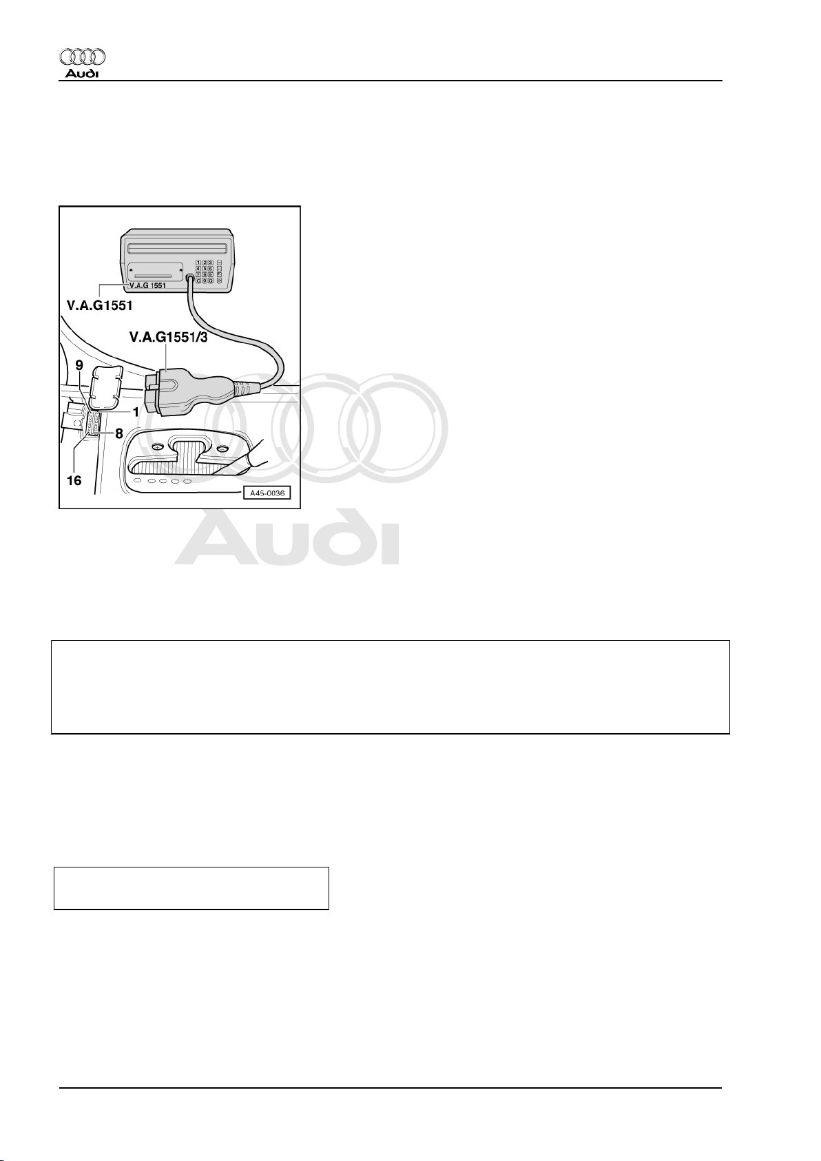
1.3 Connecting vehicle diagnostic, testing and information system VAS 5051 or fault reader
V.A.G 1551 and selecting functions . . . . . . . . . . . . . . . . . . . . . . . . . . . . . . . . . . . . . . . . . . . .2
2 Interrogating and erasing fault memory . . . . . . . . . . . . . . . . . . . . . . . . . . . . . . . . . . . . . . . .4
2.1 Interrogating and erasing fault memory . . . . . . . . . . . . . . . . . . . . . . . . . . . . . . . . . . . . . . . .4
2.2 Fault table . . . . . . . . . . . . . . . . . . . . . . . . . . . . . . . . . . . . . . . . . . . . . . . . . . . . . . . . . . . . . . . .5
3 Final control diagnosis . . . . . . . . . . . . . . . . . . . . . . . . . . . . . . . . . . . . . . . . . . . . . . . . . . . . . .15
3.1 Final control diagnosis . . . . . . . . . . . . . . . . . . . . . . . . . . . . . . . . . . . . . . . . . . . . . . . . . . . . . .15
4 Basic setting . . . . . . . . . . . . . . . . . . . . . . . . . . . . . . . . . . . . . . . . . . . . . . . . . . . . . . . . . . . . . .17
4.1 Basic setting . . . . . . . . . . . . . . . . . . . . . . . . . . . . . . . . . . . . . . . . . . . . . . . . . . . . . . . . . . . . . .17
5 Coding control unit . . . . . . . . . . . . . . . . . . . . . . . . . . . . . . . . . . . . . . . . . . . . . . . . . . . . . . . .19
5.1 Coding control unit . . . . . . . . . . . . . . . . . . . . . . . . . . . . . . . . . . . . . . . . . . . . . . . . . . . . . . . .19
6 Reading measured value block . . . . . . . . . . . . . . . . . . . . . . . . . . . . . . . . . . . . . . . . . . . . . .21
6.1 Reading measured value block . . . . . . . . . . . . . . . . . . . . . . . . . . . . . . . . . . . . . . . . . . . . . .21
24 - Mixture preparation, Injection . . . . . . . . . . . . . . . . . . . . . . . . . . . . . . . . . . . . . . . . . .22
1 Servicing Motronic injection system . . . . . . . . . . . . . . . . . . . . . . . . . . . . . . . . . . . . . . . . . . . .22
1.1 Servicing Motronic injection system . . . . . . . . . . . . . . . . . . . . . . . . . . . . . . . . . . . . . . . . . . . .22
1.2 Safety precautions . . . . . . . . . . . . . . . . . . . . . . . . . . . . . . . . . . . . . . . . . . . . . . . . . . . . . . . .22
1.3 Rules for cleanliness . . . . . . . . . . . . . . . . . . . . . . . . . . . . . . . . . . . . . . . . . . . . . . . . . . . . . .22
1.4 Technical data . . . . . . . . . . . . . . . . . . . . . . . . . . . . . . . . . . . . . . . . . . . . . . . . . . . . . . . . . . . .23
1.5 Fitting locations overview . . . . . . . . . . . . . . . . . . . . . . . . . . . . . . . . . . . . . . . . . . . . . . . . . . . .23
1.6 Dismantling and assembling fuel rail with injectors . . . . . . . . . . . . . . . . . . . . . . . . . . . . . . . .28
1.7 Removing and installing parts of intake manifold change-over . . . . . . . . . . . . . . . . . . . . . .29
1.8 Wiring and component check with test box V.A.G 1598/31 . . . . . . . . . . . . . . . . . . . . . . . . . .30
1.9 Renewing engine control unit -J220 . . . . . . . . . . . . . . . . . . . . . . . . . . . . . . . . . . . . . . . . . . . .31
1.10 Testing idling speed . . . . . . . . . . . . . . . . . . . . . . . . . . . . . . . . . . . . . . . . . . . . . . . . . . . . . . . .33
1.11 Checking fuel pressure regulator and holding pressure . . . . . . . . . . . . . . . . . . . . . . . . . . . .34
1.12 Checking injectors . . . . . . . . . . . . . . . . . . . . . . . . . . . . . . . . . . . . . . . . . . . . . . . . . . . . . . . .36
1.13 Testing injection quantity, leak-tightness and spray pattern of injectors . . . . . . . . . . . . . . . .40
1.14 Testing fuel pump relay -J17 and relay activation . . . . . . . . . . . . . . . . . . . . . . . . . . . . . . . .42
1.15 Testing air mass meter -G70 . . . . . . . . . . . . . . . . . . . . . . . . . . . . . . . . . . . . . . . . . . . . . . . .45
1.16 Checking intake air system for leaks (unmetered air) . . . . . . . . . . . . . . . . . . . . . . . . . . . . . .48
1.17 Testing intake air temperature sender -G42 . . . . . . . . . . . . . . . . . . . . . . . . . . . . . . . . . . . . . .49
1.18 Testing coolant temperature sender-G62 . . . . . . . . . . . . . . . . . . . . . . . . . . . . . . . . . . . . . . . .51
2 Testing lambda control . . . . . . . . . . . . . . . . . . . . . . . . . . . . . . . . . . . . . . . . . . . . . . . . . . . . . .52
2.1 Testing lambda control . . . . . . . . . . . . . . . . . . . . . . . . . . . . . . . . . . . . . . . . . . . . . . . . . . . . . .52
2.2 Operation of lambda control . . . . . . . . . . . . . . . . . . . . . . . . . . . . . . . . . . . . . . . . . . . . . . . . . .52
2.3 Testing lambda probe and lambda control . . . . . . . . . . . . . . . . . . . . . . . . . . . . . . . . . . . . . .53
2.4 Testing lambda probe heating . . . . . . . . . . . . . . . . . . . . . . . . . . . . . . . . . . . . . . . . . . . . . . . .57
2.5 Testing lambda probe signal wiring and activation . . . . . . . . . . . . . . . . . . . . . . . . . . . . . . . .60
2.6 Removing and installing lambda probe . . . . . . . . . . . . . . . . . . . . . . . . . . . . . . . . . . . . . . . .63
3 Testing intake manifold change-over function . . . . . . . . . . . . . . . . . . . . . . . . . . . . . . . . . . . .63
3.1 Testing intake manifold change-over function . . . . . . . . . . . . . . . . . . . . . . . . . . . . . . . . . . . .63
3.2 Testing operation . . . . . . . . . . . . . . . . . . . . . . . . . . . . . . . . . . . . . . . . . . . . . . . . . . . . . . . . . .63
3.3 Testing intake manifold change-over valve -N156 . . . . . . . . . . . . . . . . . . . . . . . . . . . . . . . .64
3.4 Testing vacuum system . . . . . . . . . . . . . . . . . . . . . . . . . . . . . . . . . . . . . . . . . . . . . . . . . . . .67
4 Testing secondary air system . . . . . . . . . . . . . . . . . . . . . . . . . . . . . . . . . . . . . . . . . . . . . . . .68
4.1 Testing secondary air system . . . . . . . . . . . . . . . . . . . . . . . . . . . . . . . . . . . . . . . . . . . . . . . .68
4.2 Testing secondary air inlet valve . . . . . . . . . . . . . . . . . . . . . . . . . . . . . . . . . . . . . . . . . . . . . .68
Audi A8 1994 ➤
Motronic injection and ignition system (6-cylinder) - Edition 02.1999
Contents i

Protected by copyright. Copying for private or commercial purposes, in part or in whole, is not
permitted unless authorised by AUDI AG. AUDI AG does not guarantee or accept any liability
with respect to the correctness of information in this document. Copyright by AUDI AG.
4.3 Testing secondary air pump relay -J299 . . . . . . . . . . . . . . . . . . . . . . . . . . . . . . . . . . . . . . . .70
5 Testing fuel tank breather system . . . . . . . . . . . . . . . . . . . . . . . . . . . . . . . . . . . . . . . . . . . .72
5.1 Testing fuel tank breather system . . . . . . . . . . . . . . . . . . . . . . . . . . . . . . . . . . . . . . . . . . . .72
5.2 Testing solenoid valve 1 for activated charcoal filter -N80 . . . . . . . . . . . . . . . . . . . . . . . . . .72
6 Testing electronic engine power control (electronic throttle) . . . . . . . . . . . . . . . . . . . . . . . .76
6.1 Testing electronic engine power control (electronic throttle) . . . . . . . . . . . . . . . . . . . . . . . .76
6.2 Operation of electronic throttle system . . . . . . . . . . . . . . . . . . . . . . . . . . . . . . . . . . . . . . . . . .76
6.3 Testing throttle valve control part -J338 . . . . . . . . . . . . . . . . . . . . . . . . . . . . . . . . . . . . . . . .76
6.4 Performing adaption of throttle valve control part . . . . . . . . . . . . . . . . . . . . . . . . . . . . . . . . . .76
6.5 Testing angle senders for throttle valve drive . . . . . . . . . . . . . . . . . . . . . . . . . . . . . . . . . . . .79
6.6 Notes on EPC warning lamp (fault warning lamp for electronic throttle) in dash panel insert
. . . . . . . . . . . . . . . . . . . . . . . . . . . . . . . . . . . . . . . . . . . . . . . . . . . . . . . . . . . . . . . . . . . . . . . .80
7 Checking accelerator position senders-G79 and -G185 . . . . . . . . . . . . . . . . . . . . . . . . . . . .81
7.1 Checking accelerator position senders-G79 and -G185 . . . . . . . . . . . . . . . . . . . . . . . . . . . .81
7.2 Checking brake light switch -F and brake pedal switch -F47 . . . . . . . . . . . . . . . . . . . . . . . .83
7.3 Testing clutch pedal switch -F36 . . . . . . . . . . . . . . . . . . . . . . . . . . . . . . . . . . . . . . . . . . . . . .85
8 Testing auxiliary signals . . . . . . . . . . . . . . . . . . . . . . . . . . . . . . . . . . . . . . . . . . . . . . . . . . . .88
8.1 Testing auxiliary signals . . . . . . . . . . . . . . . . . . . . . . . . . . . . . . . . . . . . . . . . . . . . . . . . . . . .88
8.2 Checking engine speed signal . . . . . . . . . . . . . . . . . . . . . . . . . . . . . . . . . . . . . . . . . . . . . . . .88
8.3 Testing air conditioner compressor shut-off . . . . . . . . . . . . . . . . . . . . . . . . . . . . . . . . . . . . . .88
8.4 Testing data exchange between control units . . . . . . . . . . . . . . . . . . . . . . . . . . . . . . . . . . . .90
28 - Ignition system . . . . . . . . . . . . . . . . . . . . . . . . . . . . . . . . . . . . . . . . . . . . . . . . . . . .94
1 Testing ignition system . . . . . . . . . . . . . . . . . . . . . . . . . . . . . . . . . . . . . . . . . . . . . . . . . . . . . .94
1.1 Testing ignition system . . . . . . . . . . . . . . . . . . . . . . . . . . . . . . . . . . . . . . . . . . . . . . . . . . . . . .94
1.2 General notes on ignition system . . . . . . . . . . . . . . . . . . . . . . . . . . . . . . . . . . . . . . . . . . . . . .94
1.3 Safety precautions . . . . . . . . . . . . . . . . . . . . . . . . . . . . . . . . . . . . . . . . . . . . . . . . . . . . . . . .94
1.4 Technical data for ignition system . . . . . . . . . . . . . . . . . . . . . . . . . . . . . . . . . . . . . . . . . . . .94
1.5 Removing and installing parts of the ignition system . . . . . . . . . . . . . . . . . . . . . . . . . . . . . .95
1.6 Testing ignition coils . . . . . . . . . . . . . . . . . . . . . . . . . . . . . . . . . . . . . . . . . . . . . . . . . . . . . . . .97
1.7 Testing engine speed sender -G28 . . . . . . . . . . . . . . . . . . . . . . . . . . . . . . . . . . . . . . . . . . . .101
1.8 Checking control unit voltage supply . . . . . . . . . . . . . . . . . . . . . . . . . . . . . . . . . . . . . . . . . .102
1.9 Testing knock sensor control limit . . . . . . . . . . . . . . . . . . . . . . . . . . . . . . . . . . . . . . . . . . . .104
1.10 Testing knock sensors-G61and-G66 . . . . . . . . . . . . . . . . . . . . . . . . . . . . . . . . . . . . . . . . . .104
1.11 Testing Hall senders-G40and-G163 . . . . . . . . . . . . . . . . . . . . . . . . . . . . . . . . . . . . . . . . . . . .106
Audi A8 1994 ➤
Motronic injection and ignition system (6-cylinder) - Edition 02.1999
ii Contents

Protected by copyright. Copying for private or commercial purposes, in part or in whole, is not
permitted unless authorised by AUDI AG. AUDI AG does not guarantee or accept any liability
with respect to the correctness of information in this document. Copyright by AUDI AG.
01 - Self-diagnosis
1 - Self-diagnosis of Motronic system
1.1 - Self-diagnosis of Motronic system
1.2 - Technical data for self-diagnosis
Equipment
The term "self-diagnosis" relates specifically to the electrical and electronic part of the control system.
The control unit is equipped with a fault memory so that the fault can be traced quickly in the event of an
electronic/electrical component failure or an open circuit.
The advantages of self-diagnosis can only be fully exploited by using the vehicle diagnostic, testing and infor‐
mation system VAS 5051 or the fault reader V.A.G. 1551, in operating mode 1 "Rapid data transfer."
Functions which the vehicle diagnostic, testing and information system VAS 5051 and the fault reader V.A.G
1551 can register => Page 1 , List of selectable functions.
The fault memory is equipped with a non-volatile memory and therefore does not depend on the power supply.
Faults relating to the electronic throttle are also indicated by a warning lamp in the dash panel insert.
Selectable functions when using fault reader V.A.G 1551
The requirements for selecting the desired functions can be taken from the following table.
Address words and functions on
Fault reader V.A.G 1551
Ignition on,
engine not running
Engine idling Vehicle being driven
Address words
00 Automatic test sequence yes yes yes
01 Engine electronics yes yes yes
Functions
01 Interrogate control unit version yes yes yes
02 Interrogate fault memory yes yes yes
03 Final control diagnosis yes no no
04 Basic setting yes yes yes
05 Erase fault memory yes yes yes
06 End output yes yes yes
07 Code control unit yes no no
08 Read measured value block yes yes yes
Audi A8 1994 ➤
Motronic injection and ignition system (6-cylinder) - Edition 02.1999
1.1 - Self-diagnosis of Motronic system 1

Protected by copyright. Copying for private or commercial purposes, in part or in whole, is not
permitted unless authorised by AUDI AG. AUDI AG does not guarantee or accept any liability
with respect to the correctness of information in this document. Copyright by AUDI AG.
1.3 - Connecting vehicle diagnostic, testing and information system VAS 5051 or fault reader
V.A.G 1551 and selecting functions
Test conditions
• Fuses for engine electronics OK
• Fuel pump relay OK
• Battery voltage at least 11 V
• Earth connections on engine and gearbox OK.
- Switch ignition off.
- -> Connect vehicle diagnostic, testing and information system VAS 5051 with diagnosis cable VAS 5051/1.
As an alternative, connect fault reader V.A.G 1551 with diagnosis cable V.A.G 1551/3.
Warning!
◆ When performing test-drives and checks, the vehicle diagnostic, testing and information system VAS 5051
as well as the fault reader V.A.G. 1551 may be secured only on rear seat, from where it is to be operated.
◆ Please follow safety precautions => Page 22
Note:
The following description only covers the procedure for performing self-diagnosis with fault reader V.A.G 1551.
If using vehicle diagnostic, testing and information system VAS 5051, follow the operating instructions supplied
with the equipment.
-> Indicated on display:
V.A.G - SELF DIAGNOSIS HELP
1 - Rapid data transfer*
2 - Flash code output*
* Appears alternately
- If no display appears, check diagnostic cables:
=> Current Flow Diagrams, Electrical Fault-Finding and Fitting Locations binder; Fault-finding programme: "Di‐
agnostic wiring"
Audi A8 1994 ➤
Motronic injection and ignition system (6-cylinder) - Edition 02.1999
2 01 - Self-diagnosis

Protected by copyright. Copying for private or commercial purposes, in part or in whole, is not
permitted unless authorised by AUDI AG. AUDI AG does not guarantee or accept any liability
with respect to the correctness of information in this document. Copyright by AUDI AG.
Depending on the function required:
- Switch ignition on.
or
Start the engine
=> Page 1 , table of selectable functions.
- Switch on printer with the Print button
(Warning lamp in button lights up).
- Press key 1 for "Rapid data transfer".
-> Indicated on display:
Rapid data transfer HELP
Enter address word XX
Note:
Address word 00 is used to start the automatic test sequence (i.e. fault memory interrogation for all vehicle
systems with self-diagnosis capability in "Rapid data transfer" mode).
-
Rapid data transfer Q
01 - Engine electronics
-> Press keys 0 and 1 for address word "Engine electronics" and confirm entry by pressing the Q key.
-> If the display shows one of the messages reproduced here, run through the fault-finding procedure as de‐
scribed in the Fault-Finding Programme for diagnosis wiring.
Rapid data transfer HELP
Control unit does not answer
=> Current Flow Diagrams, Electrical Fault-Finding and Fitting Locations
Rapid data transfer HELP
Fault in communication build up
Rapid data transfer HELP
K wire not switching to earth
Rapid data transfer HELP
K wire not switching to positive
-> The display on fault reader V.A.G 1551 will show the control unit identification, as in this example.
3B0907551.. 2.8l V6/5V G
D ..⇒
Coding 05753 WSC 06388
- 3B0907551.. Control unit number
(see Parts List)
- 2.8 ltr. Engine capacity
- V6/5V Engine type
(V engine, 6 cylinders, 5 valves per
cylinder)
- "G"
- or no display
With cruise control (G)
or without cruise control
- D.. Software version in control unit
- Coding 05753 Engine control unit coding; Coding ta‐
ble => Page 19
- WSC 06388 Workshop Code of the V.A.G 1551
with which the last coding was per‐
formed
Audi A8 1994 ➤
Motronic injection and ignition system (6-cylinder) - Edition 02.1999
1.3 - Connecting vehicle diagnostic, testing and information system VAS 5051 or fault
reader V.A.G 1551 and selecting functions 3

Protected by copyright. Copying for private or commercial purposes, in part or in whole, is not
permitted unless authorised by AUDI AG. AUDI AG does not guarantee or accept any liability
with respect to the correctness of information in this document. Copyright by AUDI AG.
If the coding differs from the vehicle version, then:
- Check control unit coding
=> Coding engine control unit, Page 19
- Press ⇒key.
-> Indicated on display:
Rapid data transfer HELP
Select function XX
Note:
Press the HELP key to obtain a printout of the functions which are available.
2 - Interrogating and erasing fault memory
2.1 - Interrogating and erasing fault memory
- Connect vehicle diagnostic, testing and information system VAS 5051 (or fault reader V.A.G 1551) and
select engine electronics control unit by entering address word "01" ( => Page 2 .)
When doing this the engine must be idling.
Note:
If the engine does not start, turn over the engine with the starter motor for at least 5 seconds, then leave the
ignition switched on.
- Switch on printer with the Print button
(Warning lamp in button lights up).
-> Indicated on display:
Rapid data transfer HELP
Select function XX
- Operate fault reader taking into account the information on the display:
- Press keys 0 and 2 for function "Interrogate fault memory" and confirm entry with Q key.
-> The display will show either the number of faults stored or the message "No fault recognised!".
X Faults recognised!
If no fault is stored:
- Press ⇒key.
If one or more faults are stored:
The faults stored will be displayed and printed out one after the other.
-> Indicated on display:
Rapid data transfer HELP
Select function XX
- Locate and eliminate faults printed out as per fault table
=> Page 5 .
- Press keys 0 and 5 for the function "Erase fault memory" and confirm entry with Q key.
-> Indicated on display:
Rapid data transfer
Fault memory is erased!
Audi A8 1994 ➤
Motronic injection and ignition system (6-cylinder) - Edition 02.1999
4 01 - Self-diagnosis

Protected by copyright. Copying for private or commercial purposes, in part or in whole, is not
permitted unless authorised by AUDI AG. AUDI AG does not guarantee or accept any liability
with respect to the correctness of information in this document. Copyright by AUDI AG.
Note:
If the ignition is switched off between interrogating the fault memory and erasing the fault memory, the fault
memory will not be erased. It is therefore important to follow the procedure exactly, i.e. first interrogate the fault
memory and then erase it.
- Press ⇒key.
-> Indicated on display:
Rapid data transfer HELP
Select function XX
- Press keys 0 and 6 for the function "End output" and confirm entry with the Q key.
Automatic test sequence
During test and assembly work faults can be recognised from other control units like e.g. plug disconnected.
Therefore on completion the fault memories of all control units must be interrogated and erased. To do this:
- Press key 0 twice for address word "Automatic test sequence" and confirm entry with Q key. The V.A.G
1551 transmits all known address words one after the other.
When a control unit answers with its identification the number of stored faults appears on the display or "No
fault recognised".
Any system faults that are stored will be displayed one after the other and printed out. The V.A.G 1551 will then
transmit the next address word.
-> The automatic test sequence has ended when the following appears on the display:
V.A.G - SELF-DIAGNOSIS HELP
1 - Rapid data transfer*
2 - Flash code output*
- Erase all fault memories and then carry out a road test.
- Interrogate the fault memories of all control units again using the "automatic test sequence". No faults must
be stored in fault memory.
If no fault is stored:
- Press the ⇒key.
-> Indicated on display:
Rapid data transfer HELP
Select function XX
- Press keys 0 and 6 for the "End data transfer" function and confirm input with the Q key.
2.2 - Fault table
Notes:
◆ If faults occur in the sensors and components being monitored, they will be stored in the fault memory
together with an indication of the type of fault.
◆ Faults relating to the electronic throttle are also indicated by the EPC (Electronic Power Control) warning
lamp in the dash panel insert. Notes on electronic throttle system=>Page 76 .
◆ If the connector for the engine control unit is unplugged or if the battery is disconnected, all the learned
values stored in the control unit will be erased, although the contents of the fault memory will remain intact.
The next time the engine is started the idling may be rough at first.
In addition, the following adaption procedures must be performed => Page 76 .
◆ The fault table is arranged according to the 5-digit fault codes in the left-hand column.
◆ If a fault is stored in the fault memory and then does not occur again during the next 40 engine warm-up
phases, the fault code will be automatically erased.
Audi A8 1994 ➤
Motronic injection and ignition system (6-cylinder) - Edition 02.1999
2.1 - Interrogating and erasing fault memory 5

Protected by copyright. Copying for private or commercial purposes, in part or in whole, is not
permitted unless authorised by AUDI AG. AUDI AG does not guarantee or accept any liability
with respect to the correctness of information in this document. Copyright by AUDI AG.
◆ Sporadically occurring faults (temporary faults) will be indicated on the V.A.G 1551 display as "SP". The
word "sporadic" means "intermittent" or "occurring at irregular intervals".
◆ Components that are indicated as being faulty by the V.A.G 1551/VAS 5051 should not be renewed imme‐
diately. Always start by checking the wiring, connectors and earth connections for the component using the
current flow diagram. This is particularly important in the case of sporadic faults (indicated by the letters
"SP"on the fault reader display).
Fault code Readout on fault reader display Fault rectification
SAE V.A.G
P0102 16486 Air mass meter -G70
Signal too small
Test air mass meter
P0103 16487 Air mass meter -G70
Signal too large
=> Page 45
P0112 16496 Intake air temp. sender -G42
Signal too small
Test intake air temperature sender
P0113 16497 Intake air temp. sender -G42
Signal too large
=> Page 49
P0116 16500 Coolant temp. sender -G62
Implausible signal
Test coolant temperature sender
P0117 16501 Coolant temp. sender -G62
Signal too small
=> Page 51
P0118 16502 Coolant temp. sender -G62
Signal too large
Fault code Readout on fault reader display Fault rectification
SAE V.A.G
P0130 16514 Bank 1, Probe 1
Electrical fault in current circuit
Test lambda control
P0131 16515 Bank 1, Probe 1
Voltage too low
=> Page 52
P0132 16516 Bank 1, Probe 1
Voltage too high
P0134 16518 Bank 1, Probe 1
No activity
Fault code Readout on fault reader display Fault rectification
SAE V.A.G
P0150 16534 Bank 2, Probe 1
Electrical fault in current circuit
Test lambda control
P0151 16535 Bank 2, Probe 1
Voltage too low
=> Page 52
P0152 16536 Bank 2, Probe 1
Voltage too high
P0154 16538 Bank 2, Probe 1
No activity
P0321 16705 Engine speed sender -G28
Implausible signal
Test engine speed sender
=> Page 101
P0322 16706 Engine speed sender -G28
No signal
Fault code Readout on fault reader display Fault rectification
SAE V.A.G
Audi A8 1994 ➤
Motronic injection and ignition system (6-cylinder) - Edition 02.1999
6 01 - Self-diagnosis

Protected by copyright. Copying for private or commercial purposes, in part or in whole, is not
permitted unless authorised by AUDI AG. AUDI AG does not guarantee or accept any liability
with respect to the correctness of information in this document. Copyright by AUDI AG.
P0327 16711 Knock sensor 1 -G61
Signal too small
Test knock sensor
P0328 16712 Knock sensor 1 -G61
Signal too large
=> Page 104
P0332 16716 Knock sensor 2 -G66
Signal too small
P0333 16717 Knock sensor 2 -G66
Signal too large
P0501 16885 Vehicle speed signal
Implausible signal
Interrogate fault memory of dash panel insert
=> Electrical system; Repair group 01; Self-diagnosis of dash
panel insert; Interrogating fault memory Self-diagnosis of dash
panel insert; Interrogating fault memory
P0560 16944 Voltage supply
Implausible signal
Test voltage supply
=> Page 102
P0562 16946 Voltage supply
Voltage too low
P0563 16947 Voltage supply
Voltage too high
Fault code Readout on fault reader display Fault rectification
SAE V.A.G
P0571 16955 Brake light switch -F
Implausible signal
Test brake light switch
=> Page 83
P0601 16985 Control unit defective Renew engine control unit
P0604 16988 Control unit defective => Page 31
P0605 16989 Control unit defective
P0606 16990 Control unit defective
P1102 17510 Bank 1 - Probe 1, Heating element circuit
Short to Positive
Test lambda probe heating
=> Page 57
P1107 17515 Bank 2 - Probe 1, Heating element circuit
Short to Positive
P1111 17519 Lambda control (Bank 1), System too lean Test lambda control
Page => 52 .
P1112 17520 Lambda control (Bank 1), System too rich
Fault code Readout on fault reader display Fault rectification
SAE V.A.G
P1113 17521 Bank 1 - Probe 1
Internal resistance too great
Test lambda probe heating
=> Page 57
P1115 17523 Bank 1 - Probe 1, Heating element circuit
Short to Earth
P1116 17524 Bank 1 - Probe 1, Heating element circuit
Open circuit
P1119 17527 Bank 2 - Probe 1, Heating element circuit
Short to Earth
P1120 17528 Bank 2 - Probe 1, Heating element circuit
Open circuit
Fault code Readout on fault reader display Fault rectification
SAE V.A.G
Audi A8 1994 ➤
Motronic injection and ignition system (6-cylinder) - Edition 02.1999
2.2 - Fault table 7

Protected by copyright. Copying for private or commercial purposes, in part or in whole, is not
permitted unless authorised by AUDI AG. AUDI AG does not guarantee or accept any liability
with respect to the correctness of information in this document. Copyright by AUDI AG.
Fault code Readout on fault reader display Fault rectification
P1127 17535 Bank 1, Mixture adaption (mult.)
System too rich
Take car for test drive
(fuel in oil)
Check fuel system pressure
=> Page 34
P1128 17536 Bank 1, Mixture adaption (mult.)
System too lean
Test air mass meter
=> Page 45
P1129 17537 Bank 2, Mixture adaption (mult.)
System too rich
Test lambda probe
=> Page 52
P1130 17538 Bank 2, Mixture adaption (mult.)
System too lean
Test injectors
=> Page 40
P1131 17539 Bank 2 - Probe 1
Internal resistance too great
Test lambda probe heating
=> Page 57
Note:
mult. = multiplicative, i.e. the fault occurs across the whole range of engine speeds and engine loads.
Fault code Readout on fault reader display Fault rectification
SAE V.A.G
P1136 17544 Bank 1, Mixture adaption (add.)
System too lean
Take car for test drive
(fuel in oil)
P1137 17545 Bank 1, Mixture adaption (add.)
System too rich
Check fuel system pressure
=> Page 34
P1138 17546 Bank 2, Mixture adaption (add.)
System too lean
Test air mass meter
=> Page 45
P1139 17547 Bank 2, Mixture adaption (add.)
System too rich
Test lambda probe
=> Page 72
Note:
add. = additive, i.e. the fault only occurs at idling speed.
Fault code Readout on fault reader display Fault rectification
SAE V.A.G
P1147 17555 Lambda control, Bank 2
System too lean
P1148 17556 Lambda control, Bank 2
System too rich
Test lambda control
P1149 17557 Lambda control, Bank 1
Implausible control value
=>Page 52 .
P1150 17558 Lambda control, Bank 2
Implausible control value
P1171 17579 Angle sens. 2 for throt. valve drive -G188
Implausible signal 1)
Test angle sender
for throttle valve drive
P1172 17580 Angle sens. 2 for throt. valve drive -G188
Signal too small 1)
=> Page 79
P1173 17581 Angle sens. 2 for throt. valve drive -G188
Signal too large 1)
1) If this fault occurs the engine control unit activates the EPC warning lamp in the dash panel insert.
Notes on EPC warning lamp =>Page 80 .
Audi A8 1994 ➤
Motronic injection and ignition system (6-cylinder) - Edition 02.1999
8 01 - Self-diagnosis

Protected by copyright. Copying for private or commercial purposes, in part or in whole, is not
permitted unless authorised by AUDI AG. AUDI AG does not guarantee or accept any liability
with respect to the correctness of information in this document. Copyright by AUDI AG.
Note:
add. = additive, i.e. the fault only occurs at idling speed.
Fault code Readout on fault reader display Fault rectification
SAE V.A.G
P1213 17621 Injector Cyl. 1 -N30
Short to Positive
Test injectors
P1214 17622 Injector Cyl. 2 -N31
Short to Positive
=>Page 36
P1215 17623 Injector Cyl. 3 -N32
Short to Positive
P1216 17624 Injector Cyl. 4 -N33
Short to Positive
P1217 17625 Injector Cyl. 5 -N83
Short to Positive
P1218 17626 Injector Cyl. 6 -N84
Short to Positive
Fault code Readout on fault reader display Fault rectification
SAE V.A.G
P1225 17633 Injector Cyl. 1 -N30
Short to Earth
Test injectors
P1226 17634 Injector Cyl. 2 -N31
Short to Earth
=>Page 36
P1227 17635 Injector Cyl. 3 -N32
Short to Earth
P1228 17636 Injector Cyl. 4 -N33
Short to Earth
P1229 17637 Injector Cyl. 5 -N83
Short to Earth
P1230 17638 Injector Cyl. 6 -N84
Short to Earth
Fault code Readout on fault reader display Fault rectification
SAE V.A.G
P1237 17645 Injector Cyl. 1 -N30
Open circuit
Test injectors
P1238 17646 Injector Cyl. 2 -N31
Open circuit
=>Page 36
P1239 17647 Injector Cyl. 3 -N32
Open circuit
P1240 17648 Injector Cyl. 4 -N33
Open circuit
P1241 17649 Injector Cyl. 5 -N83
Open circuit
P1242 17650 Injector Cyl. 6 -N84
Open circuit
Fault code Readout on fault reader display Fault rectification
SAE V.A.G
Audi A8 1994 ➤
Motronic injection and ignition system (6-cylinder) - Edition 02.1999
2.2 - Fault table 9

Protected by copyright. Copying for private or commercial purposes, in part or in whole, is not
permitted unless authorised by AUDI AG. AUDI AG does not guarantee or accept any liability
with respect to the correctness of information in this document. Copyright by AUDI AG.
P1325 17733 Knock control Cyl. 1
Control limit reached
Test knock control
P1326 17734 Knock control Cyl. 2
Control limit reached
=> Page 104
P1327 17735 Knock control Cyl. 3
Control limit reached
P1328 17736 Knock control Cyl. 4
Control limit reached
P1329 17737 Knock control Cyl. 5
Control limit reached
P1330 17738 Knock control Cyl. 6
Control limit reached
Fault code Readout on fault reader display Fault rectification
SAE V.A.G
P1335 17743 Engine torque monitoring 2
Control limit surpassed 1)
Test throttle valve control part
=> Page 31
P1336 17744 Engine torque monitoring
Control limit surpassed
Renew engine control unit
=> Page 31
1) If this fault occurs the engine control unit activates the EPC warning lamp in the dash panel insert.
Notes on EPC warning lamp =>Page 80 .
Fault code Readout on
fault reader
display
Fault rectification
SAE V.A.G
P1337 17745 Bank 1, Cam‐
shaft pos. sen‐
sor => -G163
Short to Earth
Test Hall sender
P1338 17746 Bank 1, Cam‐
shaft pos. sen‐
sor => -G163
Open circuit /
Short to Posi‐
tive
=> Page 106
P1340 17748 Camshaft
pos. / Crank‐
shaft pos.
sens.
Wrong alloca‐
tion
Test phase position of
hall senders
=> Page 106
P1347 17755 Bank 2, Cam‐
shaft pos. /
Crankshaft
pos. sens.
Wrong alloca‐
tion
P1386 17794 Control unit de‐
fective
Renew engine control
unit
=> Page 31
P1387 17795 Control unit de‐
fective
Audi A8 1994 ➤
Motronic injection and ignition system (6-cylinder) - Edition 02.1999
10 01 - Self-diagnosis

Protected by copyright. Copying for private or commercial purposes, in part or in whole, is not
permitted unless authorised by AUDI AG. AUDI AG does not guarantee or accept any liability
with respect to the correctness of information in this document. Copyright by AUDI AG.
P1388 17796 Control unit de‐
fective 1)
1) If this fault occurs the engine control unit activates the EPC warning lamp in the dash panel insert.
Notes on EPC warning lamp =>Page 80 .
Fault code Readout on
fault reader
display
Fault rectification
SAE V.A.G
P1391 17799 Bank 2, Cam‐
shaft pos. sen‐
sor => -G40
Short to Earth
Test Hall sender
P1392 17800 Bank 2, Cam‐
shaft pos. sen‐
sor => -G40
Open circuit /
Short to Posi‐
tive
=> Page 106
P1393 17801 Ignition output
1: Electrical
fault in current
circuit
Test activation and/or
wiring from engine con‐
trol unit to ignition out‐
put stage => Page
99 .
P1394 17802 Ignition output
2: Electrical
fault in current
circuit
P1395 17803 Ignition output
3: Electrical
fault in current
circuit
Note on fault codes 17801, 17802, 17803:
"Ignition output 1", "Ignition output 2" and "Ignition output 3" refer to the outputs at the engine control unit from
which the control unit activates the output stage on the ignition coils.
Fault code Readout on
fault reader dis‐
play
Fault rectification
SAE V.A.G
P1410 17818 Tank breather
valve -N80
Short to Posi‐
tive
Test solenoid valve 1
for activated charcoal
filter => Page 72
P1420 17828 Secondary air
inlet valve -
N112
Electrical fault
in current circuit
P1421 17829 Secondary air
inlet valve -
N112
Short to Earth
Test secondary air in‐
let valve
=> Page 68
P1422 17830 Secondary air
inlet valve -
N112
Short to Posi‐
tive
Audi A8 1994 ➤
Motronic injection and ignition system (6-cylinder) - Edition 02.1999
2.2 - Fault table 11

Protected by copyright. Copying for private or commercial purposes, in part or in whole, is not
permitted unless authorised by AUDI AG. AUDI AG does not guarantee or accept any liability
with respect to the correctness of information in this document. Copyright by AUDI AG.
P1425 17833 Tank breather
valve -N80
Short to Earth
Test solenoid valve 1
for activated charcoal
filter => Page 72
P1426 17834 Tank breather
valve -N80
Open circuit
Fault code Readout on
fault reader
display
Fault rectification
SAE V.A.G
P1432 17840 Secondary air
inlet valve -
N112
Open circuit
Test secondary air inlet
valve
=> Page 68
P1433 17841 Relay for sec‐
ondary air
pump -J299
Open circuit
P1434 17842 Relay for sec‐
ondary air
pump -J299
Short to Posi‐
tive
Test secondary air
pump relay => Page
70
P1435 17843 Relay for sec‐
ondary air
pump -J299
Short to Earth
P1436 17844 Relay for sec‐
ondary air
pump -J299
Electrical fault
in current cir‐
cuit
Fault code Readout on
fault reader dis‐
play
Fault rectification
SAE V.A.G
P1500 17908 Fuel pump re‐
lay -J17
Electrical fault
in current cir‐
cuit
Test fuel pump relay
P1501 17909 Fuel pump re‐
lay -J17
Short to Earth
=> Page 42
P1502 17910 Fuel pump re‐
lay -J17
Short to Posi‐
tive
P1511 17919 Intake manif.
change-over
valve -N156
Electrical fault
in current cir‐
cuit
Test intake manifold
change-over function
P1512 17920 Intake manif.
change-over
valve -N156
Short to Posi‐
tive
=> Page 64 .
Audi A8 1994 ➤
Motronic injection and ignition system (6-cylinder) - Edition 02.1999
12 01 - Self-diagnosis

Protected by copyright. Copying for private or commercial purposes, in part or in whole, is not
permitted unless authorised by AUDI AG. AUDI AG does not guarantee or accept any liability
with respect to the correctness of information in this document. Copyright by AUDI AG.
P1515 17923 Intake manif.
change-over
valve -N156
Short to Earth
P1516 17924 Intake manif.
change-over
valve -N156
Open circuit
Fault code Readout on fault reader display Fault rectification
SAE V.A.G
P1519 17927 Bank 1, Variable valve timing
Faulty
=> Mechanics; Repair group 15; Testing camshaft timing con‐
trol, Testing operation of camshaft timing control Testing cam‐
shaft timing control, Testing operation of camshaft timing
control
P1522 17930 Bank 2, Variable valve timing
Faulty
P1529 17937 Variable valve timing
Short to Positive
P1530 17938 Variable valve timing
Short to Earth
=> Mechanics; Repair group 15; Testing camshaft timing con‐
trol, Testing solenoid valves forcamshaft adjustment Testing
camshaft timing control, Testing solenoid valves forcamshaft
adjustment
P1531 17939 Variable valve timing
Open circuit
Fault code Readout on fault reader display Fault rectification
SAE V.A.G
P1539 17947 Clutch pedal switch -F36
Implausible signal
Test clutch pedal switch
=> Page 85
P1542 17950 Angle sender for throt. val. drive -G187
Implausible signal 1)
Test angle sender
for throttle valve drive
P1543 17951 Angle sender for throt. val. drive -G187
Signal too small 1)
=> Page 79
P1544 17952 Angle sender for throt. val. drive -G187
Signal too large 1)
P1545 17953 Throttle valve control
Faulty 1)
Test throttle valve control part
=> Page 76
P1558 17966 Throttle valve drive -G186
Electrical fault in current circuit 1)
P1559 17967 Throttle valve control part -J338
Fault in basic setting 1)
Perform adaption
=> Page 76
1) If this fault occurs the engine control unit activates the EPC warning lamp in the dash panel insert.
Notes on EPC warning lamp =>Page 80 .
Fault code Readout on fault reader display Fault rectification
SAE V.A.G
P1560 17968 Maximum engine revs surpassed Repair mechanical damage
P1564 17972 Throttle valve control part -J338
Low voltage at base setting
Charge battery or
test throttle valve control part => Page 76 .
P1565 17973 Throttle valve control part -J338
Lower stop is not reached 1)
Test throttle valve control part
=> Page 76
Audi A8 1994 ➤
Motronic injection and ignition system (6-cylinder) - Edition 02.1999
2.2 - Fault table 13

Protected by copyright. Copying for private or commercial purposes, in part or in whole, is not
permitted unless authorised by AUDI AG. AUDI AG does not guarantee or accept any liability
with respect to the correctness of information in this document. Copyright by AUDI AG.
P1568 17976 Throttle valve control part -J338
Mechanical fault 1)
P1569 17977 CCS switch -E45
Implausible signal
=> Electrical system;
=> Repair group 01; Self-diagnosis of cruise control system
(CCS)
1) If this fault occurs the engine control unit activates the EPC warning lamp in the dash panel insert.
Notes on EPC warning lamp =>Page 80 .
Fault code Readout on fault reader display Fault rectification
SAE V.A.G
P1570 17978 Engine control unit
blocked
Perform adaption of electronic immobilizer to engine control
unit
=> Electrical system; Repair group 01; Self-diagnosis for im‐
mobilizer
P1579 17987 Throttle valve control part -J338
Adaption not started
Check requirements for performing adaption
=> Page 76 .
P1600 18008 Voltage supply Kl. 15
Voltage too low
Test voltage supply to
engine control unit
P1602 18010 Voltage supply Kl. 30
Voltage too low
=> Page 102
P1603 18011 Control unit defective Renew engine control unit
=> Page 31
P1604 18012 Control unit defective 1)
P1612 18020 Engine control unit
Wrongly coded
Check coding => Page 19 .
P1626 18034 Data bus drive
No message from gearbox CU
Test CAN data bus
=>Page 90
1) If this fault occurs the engine control unit activates the EPC warning lamp in the dash panel insert.
Notes on EPC warning lamp =>Page 80 .
Fault code Readout on fault reader display Fault rectification
SAE V.A.G
P1630 18038 Accelerator position sender -G79
Signal too small 1)
P1631 18039 Accelerator position sender -G79
Signal too large 1)
Test accelerator position sender
=>Page 81
P1633 18041 Accelerator position sender 2 -G185
Signal too small 1)
P1634 18042 Accelerator position sender 2 -G185
Signal too large 1)
P1639 18047 Accelerator position sender 1/2 -G79/-G185
Implausible signal 1)
1) If this fault occurs the engine control unit activates the EPC warning lamp in the dash panel insert.
Notes on EPC warning lamp =>Page 80 .
Fault code Readout on fault reader display Fault rectification
SAE V.A.G
P1640 18048 Control unit
defective
Renew engine control unit
=> Page 31
Audi A8 1994 ➤
Motronic injection and ignition system (6-cylinder) - Edition 02.1999
14 01 - Self-diagnosis

Protected by copyright. Copying for private or commercial purposes, in part or in whole, is not
permitted unless authorised by AUDI AG. AUDI AG does not guarantee or accept any liability
with respect to the correctness of information in this document. Copyright by AUDI AG.
P1648 18056 Data bus drive defective Test CAN data bus =>Page 90 .
P1649 18057 Data bus drive
No message from ABS CU
Test CAN data bus =>Page 90 .
P1650 18058 Data bus drive
No message from dash panel insert
Test CAN data bus =>Page 90 .
P1853 18261 Data bus drive
Implausible message from ABS CU
Test CAN data bus =>Page 90 .
3 - Final control diagnosis
3.1 - Final control diagnosis
Notes:
◆ The final control diagnosis can only be performed with the ignition switched on and the engine not running.
◆ The final control diagnosis is terminated if the engine is started or if an engine speed pulse is detected.
◆ During the final control diagnosis, each control element is activated for about 1 minute unless the test pro‐
gramme is deliberately advanced to the next control element by pressing the ⇒ key.
◆ The control elements can be tested either by listening or by touching.
◆ If the final control diagnosis is to be repeated, the engine must be started. (The engine control unit needs
to detect an engine speed of more than 300 rpm.)
◆ The electric fuel pump runs continuously throughout the final control diagnosis.
The final control diagnosis activates the following components in the stated sequence:
1. Solenoid valve 1 for activated charcoal filter -N80
(fuel tank breather valve)
2. Secondary air inlet valve -N112
(only on vehicles with secondary air system)
3. Relay for secondary air pump -J299
(only on vehicles with secondary air system)
4. Intake manifold change-over valve -N156
5. Camshaft timing control 1 (camshaft adjustment valves 1 and 2,
-N205 and -N208)
Test requirements
• Fuses for engine electronics okay
• Fuel pump relay okay
- Connect vehicle diagnostic, testing and information system VAS 5051 (or fault reader V.A.G 1551) and
select engine electronics control unit by entering address word "01" ( => Page 2 .)
When doing this the ignition must be switched on.
-> Indicated on display:
Rapid data transfer HELP
Select function XX
- Press keys 0 and 3 for the function "Final control diagnosis".
-> Indicated on display:
Rapid data transfer Q
03-Final control diagnosis
Audi A8 1994 ➤
Motronic injection and ignition system (6-cylinder) - Edition 02.1999
2.2 - Fault table 15

Protected by copyright. Copying for private or commercial purposes, in part or in whole, is not
permitted unless authorised by AUDI AG. AUDI AG does not guarantee or accept any liability
with respect to the correctness of information in this document. Copyright by AUDI AG.
Activating solenoid valve for activated charcoal filter
(fuel tank breather valve)
- Confirm input with Q key.
Note:
The fuel pump relay should pick up and the fuel pump should run. Fuel flow at the fuel pressure regulator will
be clearly audible. If the fuel pump does not run, test activation
=>Page 42
-> Indicated on display:
Final control diagnosis
Tank breather valve -N80
The solenoid valve will continue to be activated (i.e. will click) for about 1 minute unless the ⇒ key is pressed
to deliberately advance the programme to the next control element.
If the solenoid valve is not actuated (does not click):
- Test solenoid valve 1 for activated charcoal filter -N80
=> Page 72 .
Activating secondary air inlet valve
(only on vehicles with secondary air system)
- Press ⇒key.
-> Indicated on display:
Final control diagnosis
Secondary air inlet valve -N112
The solenoid valve will continue to be activated (i.e. will click) for about 1 minute unless the ⇒ key is pressed
to deliberately advance the programme to the next control element.
If the secondary air inlet valve does not click:
Test secondary air inlet valve =>Page 68 or
=> Mechanics; Repair Group 26; Secondary air system Secondary air system
Activating relay for secondary air pump
(only on vehicles with secondary air system)
- Press ⇒key.
-> Indicated on display:
Final control diagnosis
Secondary air pump relay -J299
The secondary air pump relay (J299) activates the secondary air pump motor (V101) which runs at intervals
for about one minute, or until the final control diagnosis is advanced to the next control element by pressing
the ⇒ key.
If the secondary air pump motor (V101) does not run at intervals:
Testsecondary air pump relay
=>Page 70 , or
Audi A8 1994 ➤
Motronic injection and ignition system (6-cylinder) - Edition 02.1999
16 01 - Self-diagnosis
Other manuals for A8 1994
2
Table of contents
Other Audi Automobile manuals

Audi
Audi Avant RS2 Instruction manual

Audi
Audi 2003 A8 Instruction manual

Audi
Audi RS 3 LMS SEQ User manual

Audi
Audi Q3 2024 User manual

Audi
Audi 2003 A8 Instruction manual

Audi
Audi Q7 2015 User manual

Audi
Audi 100 1991 Instruction manual

Audi
Audi RS 4 CABRIOLET User manual

Audi
Audi R8 2008 Installation guide

Audi
Audi A4 User manual

Audi
Audi AS Coupe 2016 User manual

Audi
Audi Q5 2009 User manual

Audi
Audi R8 - QUICK EFEENCE GUIDE User manual

Audi
Audi A5 SPORTBACK Assembly instructions

Audi
Audi q7 2017 User manual

Audi
Audi A8 User manual

Audi
Audi allroad 2001 User manual

Audi
Audi Q5 80A 2017 User manual

Audi
Audi AS Coupe 2017 User manual

Audi
Audi Audi 80 1987 Instruction manual