Audio Ltd. A10-TX User manual
A10-TX
Digital Transmitter
—User Guide —
- 2 -
A10-TX User Guide
Table of Contents
Copyright / Doc Rev History Info . . . . . 2
Table of Contents . . . . . . . . . . . . . . 2
Overview . . . . . . . . . . . . . . . . . . 3
Key Features . . . . . . . . . . . . . . . 3
System Quickstart . . . . . . . . . . . . . 3
At the Receiver . . . . . . . . . . . . . . 3
At the Transmitter . . . . . . . . . . . . 3
At the Receiver . . . . . . . . . . . . . . 4
Connectors, Controls Description . . . . 5
Powering . . . . . . . . . . . . . . . . . . 6
Main Display . . . . . . . . . . . . . . . . 6
Menu Control and Menu Selections . . . 7
Main Menu . . . . . . . . . . . . . . . . 7
Audio Setup Menu . . . . . . . . . . . . 8
Record / TC Menu . . . . . . . . . . . . 8
Settings Menu . . . . . . . . . . . . . . 9
System Menu . . . . . . . . . . . . . . 9
Basic Operation . . . . . . . . . . . . . . 10
Frequency Selection . . . . . . . . . . 10
Channel, Sub Channel, Frequency . . 10
Audio Input and Control . . . . . . . . . 10
Lavalier Microphones . . . . . . . . . . 10
Balanced Microphones with Phantom . 11
Line-Level Sources . . . . . . . . . . . 11
Audio Level Control . . . . . . . . . . . 11
Antennas . . . . . . . . . . . . . . . . . 11
Recording . . . . . . . . . . . . . . . . 11
Record Control . . . . . . . . . . . . . . 11
File Storage . . . . . . . . . . . . . . . 12
File Conversion .MIC to .WAV . . . . . . 12
Timecode and Time-of-Day Clocks . . 12
Time-of-Day Clock . . . . . . . . . . . 12
Timecode Clock . . . . . . . . . . . . . 12
Timecode Output . . . . . . . . . . . . 13
Remote Control . . . . . . . . . . . . . . . 13
Firmware Updates . . . . . . . . . . . . . 14
Specifications . . . . . . . . . . . . . . . . 14
Input Connector Wiring Diagram . . . . 15
Battery Runtime Chart . . . . . . . . . . . 15
Certifications . . . . . . . . . . . . . . . . 15
Industry Canada Conformity . . . . . . 15
FCC Conformity . . . . . . . . . . . . . 16
Minimize RF Exposure . . . . . . . . . . 16
Frequency Tables . . . . . . . . . . . . . . 17
X Frequencies (6 MHz Per TV Channel) 17
Y Frequencies (7 MHz Per TV Channel) 18
Z Frequencies (8 MHz Per TV Channel) 19
Channel Assignments by Region . . . . 19
Copyright / Doc Rev History Info
Model A10-TX only. See separate documentation for A10-TX-US model.
Copyright © 2018Audio Ltd. All rights reserved. | www.audioltd.com
Revision Date Description
1A Dec 2017 Initial Publication
1B Feb 2018 Added note re: Bluetooth remote range

- 3 -
A10-TX User Guide
Overview
The A10 Digital Wireless System meets the demanding requirements of the professional sound
community engaged in lm and television production. It oers superb audio and RF perfor-
mance.
The digital RF transmission of the A10 system allows the user to operate up to 20 channels in
an 8 MHz TV channel, maximising spectrum eciency without compromising on range, audio
quality or latency.
The A10-TX transmitter incorporates Audio Ltd’s proprietary digital modulation scheme whilst
maintaining the high audio quality that Audio Ltd has become renowned for, and with extremely
low end-to-end latency of 2 mS.
The A10-TX has an intuitive menu system allowing the user to become familiar with settings
within a few minutes of turning it on.
Key Features
• Low-noise, studio-grade balanced input for microphones and line level signals with analogue
limiter and phantom power.
• Fully digital RF transmission
• Ultra-accurate timecode generator jam synched from external clocks.
• Integrated digital recorder records to removable microSD cards. External conversion is re-
quired to turn data les into WAV les using the free Mic2Wav app for Mac or Windows.
• Simultaneous wireless transmission and recording
• Remote controllable over Bluetooth®using the A10-TX Remote app for Android and iOS.
• Powered by easy-to-access AA batteries.

- 4 -
A10-TX User Guide
System Quickstart
The A10 Digital Wireless System is easy to use. Follow the steps below for basic setup and oper-
ation.
At the Receiver
1. Fit the included straight and right-angled antennas to the A10-RX receiver.
2. Connect the receiver to a power source. It will immediately power on.
3. Using the scanning tool in the Selection menu nd an available open frequency. If multiple
wireless systems are in use, make certain to keep frequencies least 400 kHz apart.
4. Connect the audio output from channel 1, channel 2, or both to an audio input on a mixer,
recorder, camera, or PA system.
5. Ensure that the receiver audio output type and level are set based on the input type.
At the Transmitter
1. Attach the straight antenna to the A10-TX.
2. Attach an audio source to the 3-pin LEMO input connector.
3. Insert AA batteries into the A10-TX battery compartment and power on the unit with the red
On/O button.
4. Set the audio input type to set to match the connected input.
5. Set the transmitting frequency on the A10-TX match the frequency set on the A10-RX re-
ceiver channel.
6. Adjust the audio gain according to your environment and source, taking care not to overload
the signal. This is indicated by a red LED.
At the Receiver
1. Conrm that the blue channel power LED is solid blue.
2. Conrm that the RF status LEDs and display indicate good RF strength.
3. Conrm that the audio level at the receiver corresponds to the audio connected to the
A10-TX input.
4. The system is now ready for use.
- 5 -
A10-TX User Guide
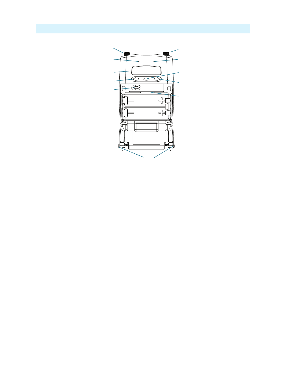
Connectors, Controls Description
2
1
3
49
12
11
6
7
10
5
8
Figure 1: A10-TX transmitter with open battery compartment
1 -Antenna Socket
SMA connector, 50 ohm, connects to includ-
ed 1/4-wave whip antenna.
2 -Power LED
Blue LED illuminates when unit is powered
on and screensave is active. Solid blue LED
can be turned o in the Menu. The LED
ashes blue when unit is in Sleep mode.
3 -Display
OLED screen. Screen automatically turns o
during operation for battery savings.
4 -Left Button
Moves selection in menu to the left, or decre-
ments values.
5 -Power Button
Press to power on the unit. Press and hold to
power down the unit.
6 -Audio Input Connector
Balanced LEMO-3 connector. Accepts mul-
tiple audio input types including unbalanced
lavalier, balanced microphone, balanced line.
Also used for timecode input and output.
7 -Input Overload LED
Red LED illuminates when clipping occurs.
8 -Menu Button
Enters the menu selection. Also used to select
options in the menu.
9 -Right Button
Moves menu selection to the right, or incre-
ments values.
10 - microSD Card Slot
The card slot is used to record les and load
rmware updates on the unit.
11 - Battery Tray
Accepts two AA LR6 batteries.
12 - Battery Door Latch
Press both latches to open the battery door.
- 6 -
A10-TX User Guide
Powering
The A10-TX is powered by two AA (LR6) batteries. For the longest runtime, use Lithium pri-
mary cells. The transmitter also accepts alkaline primary and Nickel Metal Hydride rechargeable
batteries. Select the battery type used in the menu to ensure that the battery condition is indicated
accurately in both the transmitter display and receiver.
1. Open the battery compartment by simultaneously pressing both mechanical releases of the
battery door latch. (See Figure 1.)
2. Insert two fresh AA type (LR6) batteries. Note correct battery polarity.
3. Momentarily press the red On/O button. The blue power LED will light and the display will
illuminate. The transmitter is now powered on.
4. To turn the transmitter o, press and hold the red button until the “turning o’ progress bar
completes and the unit goes dark.
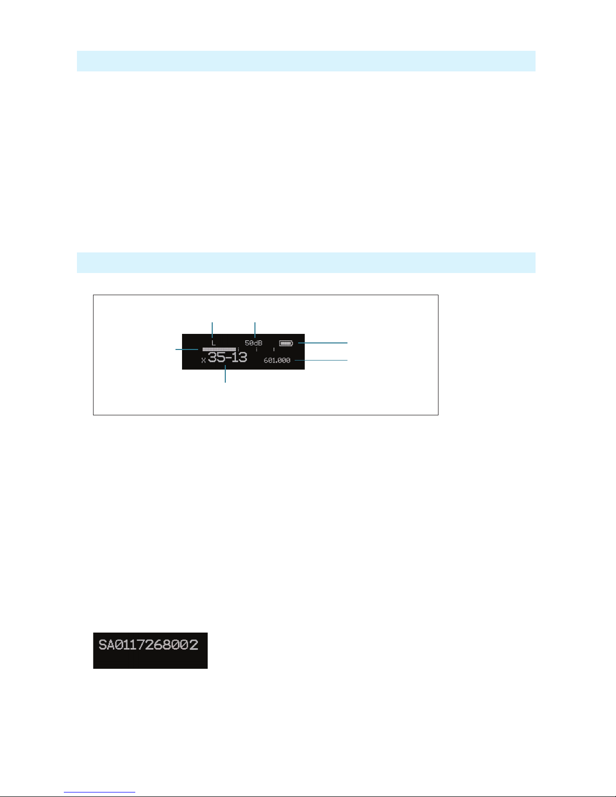
Main Display
After powering on the A10-TX the display shows the following.
Battery Condition
Input
Gain
RF Output
Power
Frequency in MHz
Frequency as
Region–Channel–Sub Channel
Input Level
Meter
• RF Output Power - three power levels are indicated, Low (10 mW), Medium (20 mW),
High (50 mW)
• Input Gain - gain applied to the input source, in dB
• Battery Condition - shows the battery voltage level of the transmitter batteries, ve-seg-
ments
• Frequency in MHz - the transmitting frequency is shown
• Frequency in Region–Channel–Sub Channel - the transmitting frequency is shown in
region, channel, and sub channel.
ªX, Y, and Z regions are selected by the TV Channel Map setting.
• Input Level Meter - shows audio input signal level
Press the Left button, to view the name of the transmitter. The serial number of the transmitter
is the default name of the transmitter. The transmitter name may be changed via the A10-TX
Remote app.
By pressing the Right button, the user can view the recording status, which displays the current
le name, time elapsed, time remaining, timecode and current frame rate.
- 7 -
A10-TX User Guide
Menu Control and Menu Selections
The A10-TX transmitter is controlled through its menu. Enter the menu via the centre Menu
button. Once in the menu, the Left and Right buttons toggle among options, and the Menu button
makes the selection.
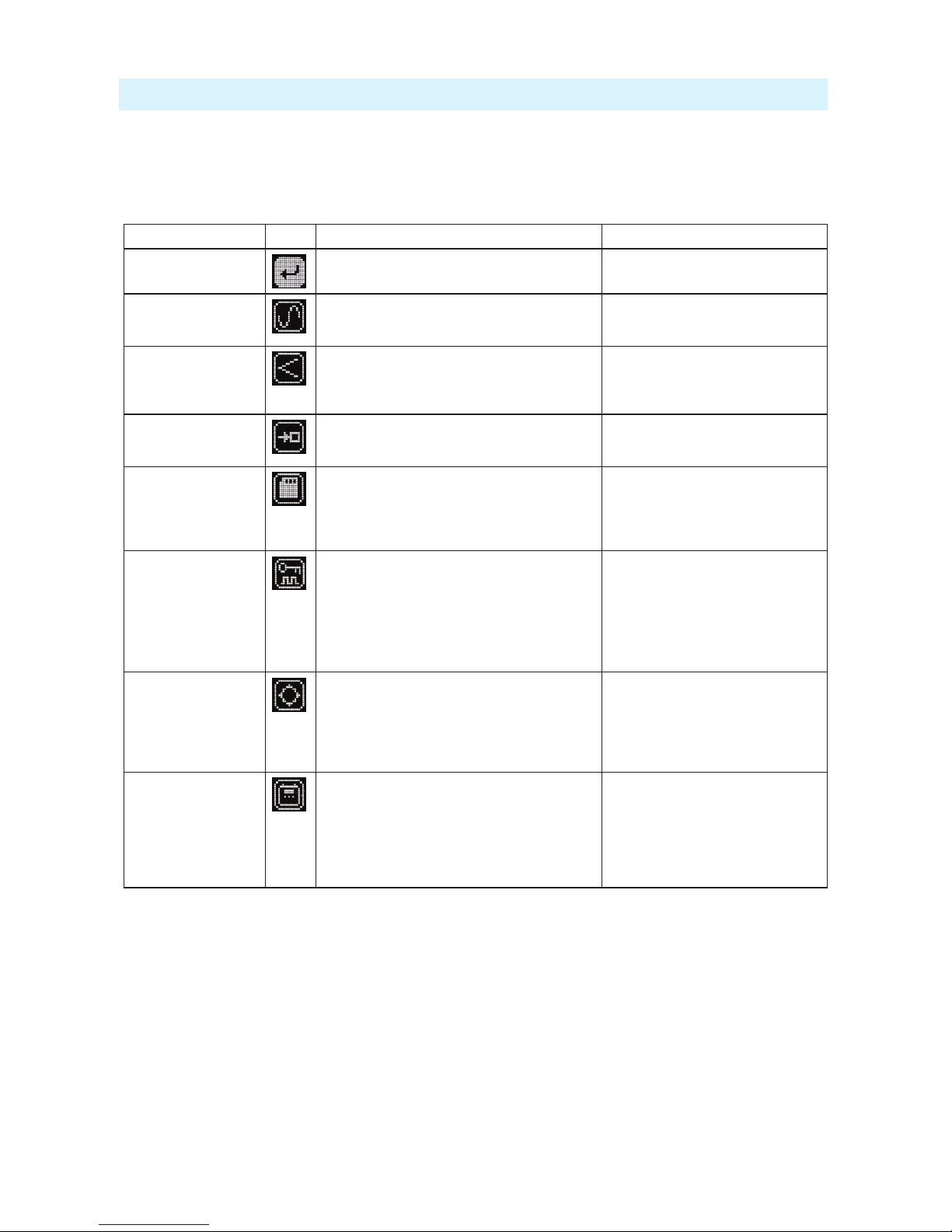
Main Menu
Selections Icon Description Options
Exit Returns to the main display screen.
Frequency Selection Sets the transmitter’s frequency. Frequency
selection and channel increments change based on
the region of operation the unit is set.
• TV Channel Increments
• Sub Channel Increments
• Frequency Increments in 25 kHz steps
Audio Gain Controls the gain range of the audio input. Gain
range is input type dependent. Gain control is in 1
dB increments.
• Lav: 0 dB to +40 dB
• Line Setting: -10 to 16 dB
• Mic setting: 16 to 40 dB w/20dB pad
• Mic setting: 36 to 60 dB
Audio Setup Enters the Audio Setup sub-menu. • Low Cut
• Limiter
• Lav / Mic / Line
Record / TC Enters the Record / TC sub-menu. • Record
• File Info
• TX / Record Mode
• Timecode
• Frame Rate
Privacy Activates transmission privacy with a four-number
key set on the transmitter and receiver. When
active, the receiver must be set to the corresponding
key for audio to pass.
New Key option generates a key. The key symbol
is displayed on main default screen when privacy
is active.
• New Key - generates new key
• O - encryption cleared, set to ----, not
active
Settings Enters the Setting sub-menu. • Bluetooth
• RF Power
• Brightness
• Battery Type
• Blue LED
• TV Ch Map
System Enters the System sub-menu. • Sleep
• Lock Menu
• Set Time/Date
• Format Card
• Restore
• Info
• Update Firmware
- 8 -
A10-TX User Guide
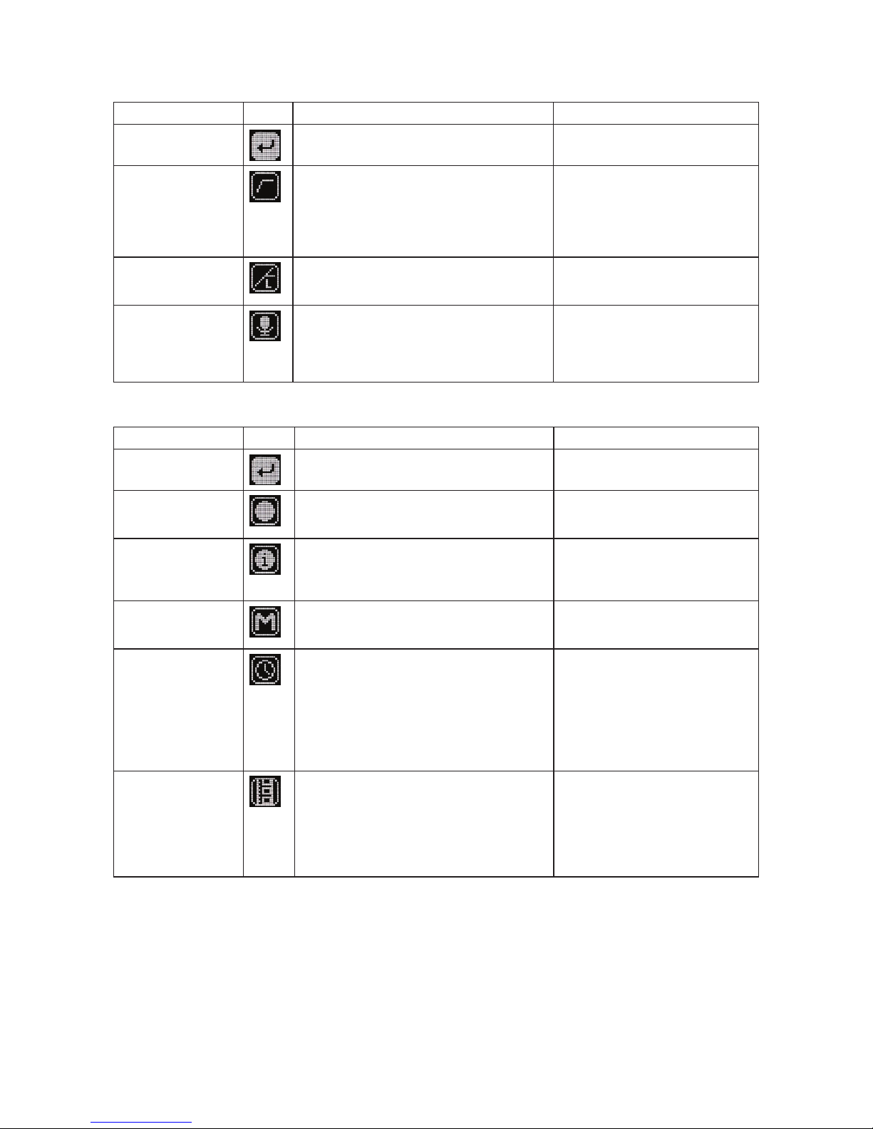
Audio Setup Menu
Selections Icon Description Options
Exit Returns to the main menu.
Low Cut Activates a low frequency cut lter to the audio
input. 18 dB/octave
• O
• 40 Hz
• 60 Hz
• 80 Hz
• 100 Hz
• 200 Hz
Limiter The limiter reduces peak levels of the analogue
audio input before digital conversion to prevent
audio overload. The recommended setting is On.
• On
• O
Lav / Mic / Line Selects the input type at the LEMO-3 connection.
ªFor Mic/Line, the AC-BAL-XLR accessory is
required.
• Lav
• Mic
• Line
• P48 - mic level with 48 V phantom
• P12 - mic level with 12 V phantom
Record / TC Menu
Selections Icon Description Options
Exit Returns to the main menu.
Record Select Record to enter Record mode (This begins
recording). The Record status is remembered
across sleep and power cycles.
File Info Shows important information about the le being
recorded.
• Time Elapsed
• Time Remaining
• Timecode
• File Name
TX / Record Mode Select the operational mode of the A10-TX. • TX/Rec - simultaneous wireless
transmission and recording
• RecOnly - recording function only
Timecode Enter Timecode menu.
Timecode values from either the attached external
timecode generator or the internal generator are
shown.
ªWhilst in this menu, wireless transmission is
suspended, and timecode may be sent via AC-
TCBNC-OUT or AC-TCLEMO accessories.
• Time of Day
• External
• Jam - applies external timecode to the
internal generator.
ªJamming to an external timecode
source requires the AC-TCBNC-IN
or AC-TCLEMO accessories.
Frame Rate Sets the frame rate of the timecode clock. Select a
rate that matches the incoming timecode rate.
ªRejam is required after setting frame rate.
• 23.98
• 24
• 25
• 29.97
• 29.97 DF
• 30
• 30 DF
- 9 -
A10-TX User Guide
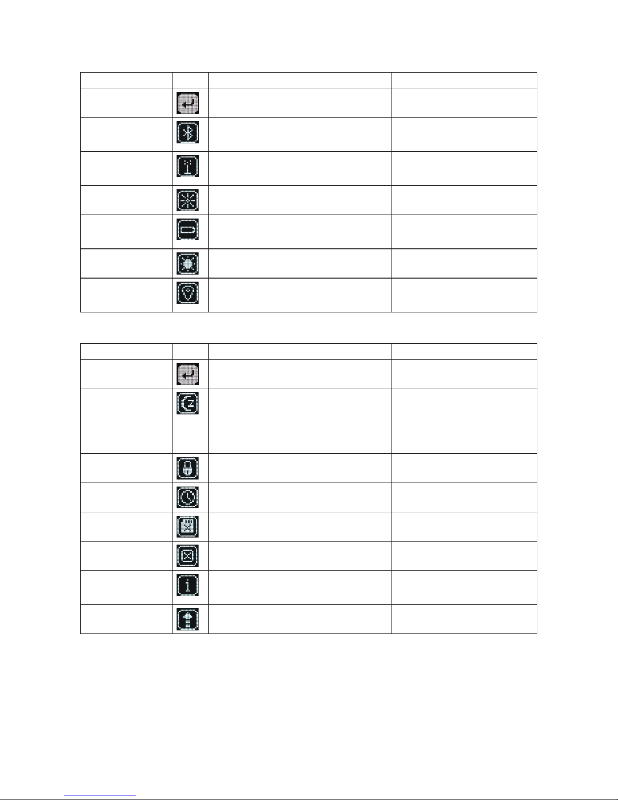
Settings Menu
Selections Icon Description Options
Exit Returns to the main menu.
Bluetooth Toggles Bluetooth On or O. Bluetooth oers
external control of the A10-TX via the A10-TX
Remote App (for iOS or Android).
• On
• O
RF Power Sets the RF output power of the transmitter. • Low - 10 mW
• Med - 20 mW
• High - 50 mW
Brightness Sets the brightness of the OLED screen Five increments, 1–5,
5 is brightest
Battery Type For accurate display of battery condition on the
transmitter and receiver select the battery type
from the available options.
• Alkaline
• NiMH
• Lithium
Blue LED If set to On, the LED illuminates blue when
powered on and screensaver is active.
• On
• O
TV Ch Map Selects the TV channel spacing in MHz to ensure
channel selection cooresponds to a specic
geographic region. See frequency chart.
• X – 6 MHz
• Y – 7 MHz
• Z – 8 MHz
System Menu
Selections Icon Description Options
Exit Returns to the main menu.
Sleep When selected, the A10-TX goes into low-power
Sleep mode. The blue LED ashes when the
unit is in a sleep state. The unit returns to normal
power operation when any button is pressed or the
transmitter is activated from the A10-TX Remote
App.
• Sleep
Lock Menu Activates a button lock to prevent unintentional
changes to menu selections.
• Unlock
• Lock
Set Time / Date Sets the time and date of the realtime clock. This
value is applied to any recorded les.
Format Card Deletes all les and data present on the inserted
microSD card and prepares it for new recordings.
OK - begins formatting process.
Restore The restore function allows the user to reset the
A10-TX to the factory default settings.
Info Shows numerous attributes of the transmitter. • Serial Number
• Firmware Revision
• Frequency Band
Update (Firmware) Updates the rmware of the transmitter using a
rmware .PRG le on the microSD card.
- 10 -
A10-TX User Guide
Basic Operation
Frequency Selection
The A10 Digital Wireless System operates in the UHF frequency band from 470 to 694 MHz.
There are three models (two in some geographic markets) of the A10-TX transmitter to cover
this frequency range.
Multiple A10 Digital Wireless systems can be used simultaneously on nearby adjacent frequen-
cies without worry of intermodulation interference since the A10 Digital Wireless System and its
digital RF transmission is inherently immune to intermodulation. Systems can be used together
when separated by at least 400 kHz. Use the scan tool on the A10-RX receiver to search for
available frequencies.
ªWhen using A10 Digital Wireless systems in conjunction with analogue RF systems, an
intermodulation plan needs to be addressed for analogue receivers.
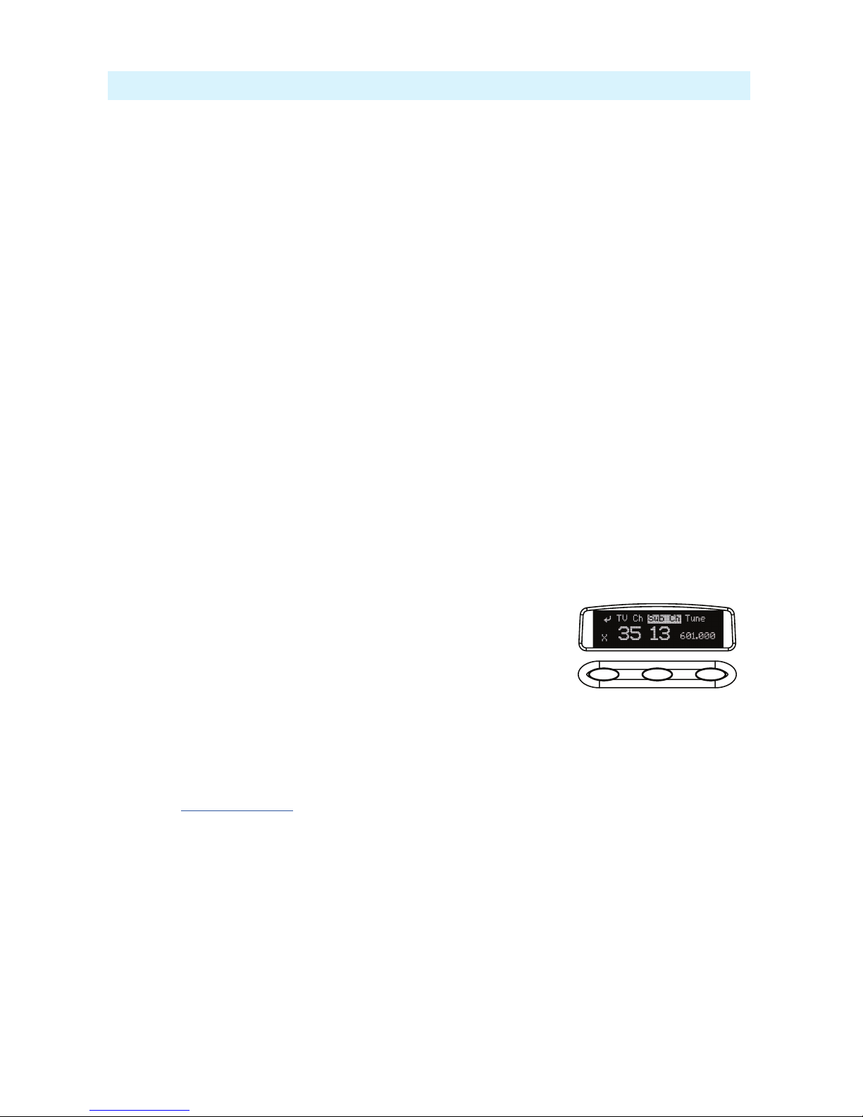
Channel, Sub Channel, Tune
To simplify frequency selection, frequencies are divided into channels and sub channels. Fre-
quencies corresponding to channels and sub channels depend on the TV Channel Mapping
selected in the Systems menu. Three options are available, 6, 7, and 8 MHz spacing, X, Y, and Z
respectively. These three settings generally correspond to three main geographic regions, USA,
Australia/New Zealand, and Europe, respectively.
• Channel - corresponds to broadcast television channels used in geographic regions. Depend-
ing on the selected channel mapping, channels cover 6, 7, or 8 MHz.
• Sub Channel - channels are divided in 400 kHz increments called sub channels to speed up
frequency selection. The number of sub channels depends on the channel mapping selected.
• Tune - specic frequencies within the transmitter’s tuning range can be selected in 25 kHz
increments.
To change TV channels, use the Left button to highlight the TV
Channel. Press the centre Menu button to select the TV channel.
Select Sub Channel until the desired sub-channel is selected.
ªRemember, for a given channel / sub channel, the actual
frequency will change depending on the TV Channel Mapping setting.
The frequency is displayed with an asterisk (*) when the tune value does not fall within the
pre-allocated sub channel.
See the Frequency Tables in this guide for a complete list of frequencies corresponding to the
channel and sub channel selections.
Audio Input and Control
The A10-TX input accepts a wide range of audio input types, including lavalier microphones,
balanced microphones, and balanced and unbalanced line level signals. 12 V and 48 V phantom
power is available for balanced microphones. The Selection Menu oers options for input type,
limiters, and low cut lter.
Lavalier Microphones
Unbalanced lavalier microphones wired in two-wire mode, are directly compatible with the
A10-TX input. When connected, the A10-TX auto-detects the presence of a lav microphone.

- 11 -
A10-TX User Guide
Balanced Microphones with Phantom
Balanced microphones, including phantom powered shotgun microphones, can be connected
to the A10-TX. 12 V and 48 V phantom power are available for microphones requiring it. For
microphones that can properly operate on 12 V phantom, such as the Schoeps CMIT, select 12
V phantom to signicantly increase battery runtime.
Line-Level Sources
Wireless systems are often used as “camera hop” systems. For most camera hop applications
the output of a eld mixer is connected to a wireless transmitter. The wireless receiver output
is connected to the camera input. The line level input selection simplies using the A10 Sys-
tem as a camera hop. Select Line in the Selection Menu to accept balanced or unbalanced line
level inputs.
ªTo connect balanced microphone or line level sources to the A10-TX, a cable wired as
described in the specications or the AC-BALXLR cable is required. This connects the shell
of the LEMO connector to pin-1 of an XLR connector.
Audio Level Control
Input levels are controlled from the Audio Gain option in the Selection Menu. The gain range
available is source-dependent as follows:
• Lav setting: 0 dB to 40 dB, 1 dB increments
• Line setting: -10 to 16 dB, 1 dB increments
• Mic setting (with 20 dB pad): 16 to 40 dB, 1 dB increments
• Mic setting (with no pad): 36 to 60 dB
Set input levels so that the limiter is active only on the strongest peaks.
Antennas
The SMA antenna connector is used to mount the included 1/4-wave whip antenna. For specialty
applications external, high-gain transmitting antennas can be attached to the SMA connector.
Make certain to connect only passive antennas to the A10-TX.
For best operation and transmission power with the included 1/4-wave antenna keep it in the free
eld. If worn on a body keep the antenna away from direct contact with the wearer’s body. When
multiple wireless systems are in use keep transmitters separated by at least 1/2-wave distance of
the transmitted frequency.
Recording
The A10-TX incorporates a data recorder that stores encoded digital waveform and timecode
data in proprietary, data-compressed binary .mic les. Files recorded on the A10-TX are not
sound les and require conversion using Audio Ltd’s Mic2Wav application. (For more informa-
tion, see File Conversion .MIC to .WAV). After conversion, a usable 48 kHz digital audio WAV
le is made. Files recorded in the A10-TX are approximately 1/3 the size of WAV les generated
from corresponding .mic les, saving valuable space on the microSD card. Files have a maxi-
mum duration of six hours. After six hours the le is automatically split into another recording.
Resulting WAV les are sample accurate across le splits.
To begin recording on the A10-TX:
»Select Menu > Record/TC > Record.
Recording can also be initiated from the A10-TX Remote App. The default le name of the
.mic le is the serial number of the A10 transmitter; however, the le name may be renamed
via the A10-TX Remote app. For more information, see Remote Control.

- 12 -
A10-TX User Guide
An indicator ashes in the display to show that the A10-TX is recording. This indicator is also
shown on the A10-RX, in the TX data screen, accessed by pressing the Right button on the
A10-RX receiver.
File Storage
Proprietary .mic les generated by the A10-TX are stored on FAT32-formatted microSD cards.
The microSD card slot is located in the battery compartment and is accessed by removing the
battery nearest the display.
If no microSD card is inserted in the unit, a ‘No card detected’ message is indicated.
New cards, or cards with material that can be overwritten, can be formatted in the A10-TX.
ªFormatting deletes all existing recordings present on the card.
There is no provision to manage les from the A10-TX. File management, including le renam-
ing and individual le deletion, is done when the microSD card is mounted to a computer via a
card reader.
File Conversion .MIC to .WAV
The .mic les generated directly on the A10-TX are not usable until converted. Audio Ltd. pro-
vides a free Mic2Wav conversion utility, available for download from the Audio Ltd. website:
www.audioltd.com. This utility—available for Mac or Windows operating systems—converts
.mic les to usable Broadcast WAV les.
Timecode and Time-of-Day Clocks
The A10-TX includes high-precision internal clocks to maintain time-of-day/date and SMPTE
timecode. These clock runs continuously when AA batteries are in the unit and draw negligible
current (less than 1 uA). The A10-TX design incorporates a supercapacitor to power the time-
of-day clock for several days in the absence of batteries. The supercapacitor reaches full charge
when batteries have been in the unit for ve minutes.
Time-of-Day Clock
The time and date clock holds time and date for les recorded on the A10-TX, and can be
used for the Time of Day timecode value.
To set time and date:
1. Enter the Selection Menu option real time clock. (Menu > System > Set Time/Date)
2. Use the centre Menu button to move between year, month, day, hours, and minutes. Use
the Left and Right buttons to change the values.
3. Press the centre Menu button to select the Return arrow and view current values. Press
again to exit.
External LTC Jamming
External LTC timecode can be applied to the A10-TX to synchronize its internal timecode
clock. Synchronization of timecode clocks is called “jam syncing”. To jam the A10-TX time-
code clock, navigate to Menu > Record/TC > Timecode in the Selection menu. Connect an
LTC timecode source to the 3-pin LEMO™ input connector using either the AC-TCLEMO or
AC-TCBNC-IN cables. The A10-TX will jam its timecode clock from the incoming timecode
signal.
ªWhilst in the Timecode menu, RF transmission and recording are deactivated on the A10-TX.
The timecode clock remains accurate when the transmitter is powered or in standby mode.
When the unit is powered down accurate timecode is held for six hours. After six hours the
timecode clock is reset to its default value.
- 13 -
A10-TX User Guide
Timecode Output
The A10-TX 3-pin LEMO connector also functions as a timecode output connection. In the
Selection menu navigate to Menu > Record/TC > Timecode. While in this screen timecode
can be sent out of the A10-TX using the AC-TCLEMO or AC-TCBNC-OUT cables.
Upon exiting the timecode menu the 3-pin LEMO reverts back to the selected lav, mic, or line
input. RF transmission is reactivated and recording is available.
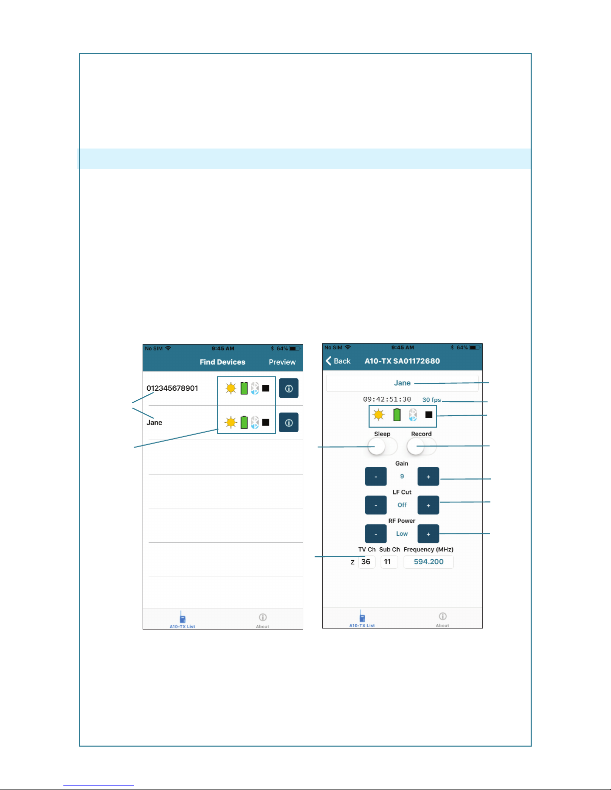
Remote Control
The A10-TX can be remotely controlled from an Android or iOS device running the A10-TX
Remote app. The app is available as a free download from the Google Play store and iOS App
store, respectively.
With the A10-TX Remote app, you can:
1 - Change the transmitter’s name; it is set to
the transmitter’s serial number by default.
2 - View timecode and frame rate
3 - Monitor Sleep status, Battery status,
Bluetooth signal strength and Record status
4 - Turn Sleep mode On/O
5 - Start/Stop recording at the transmitter
6 - Adjust Gain
7 - Set the low-cut lter
8 - Adjust RF Power
9 - Change TV Ch, Sub Ch and Frequency
1
34
9
6
7
5
8
1
2
3
Touch the unit name (left screen) to access more information (image on right) about the transmit-
ter. Touch the Circle-I icon to send identication signal to the transmitter.
ªThe Bluetooth operational range is very short. Maintain close proximity to the transmitter
for reliable connection.

- 14 -
A10-TX User Guide
Firmware Updates
Audio Ltd. issues new rmware for the A10-TX transmitter to change and introduce new fea-
tures to the unit. Make certain to register your Audio Ltd. product at the Audio Ltd. website to
receive rmware update notications.
To update rmware:
1. Download the new rmware update le from the Audio Ltd. website and copy the le onto
an approved microSD card that has been formatted in the A10-TX.
2. Insert the microSD card in the unit.
3. Insert fresh AA batteries in the unit.
4. Enter the System menu and choose Update. The unit will indicate the revision of rmare to
update.
5. Conrm that you want to update. This starts the update process.
6. Do not power down the unit until instructed to do so.
7. Verify the revision of rmware on the unit.
- 15 -
A10-TX User Guide
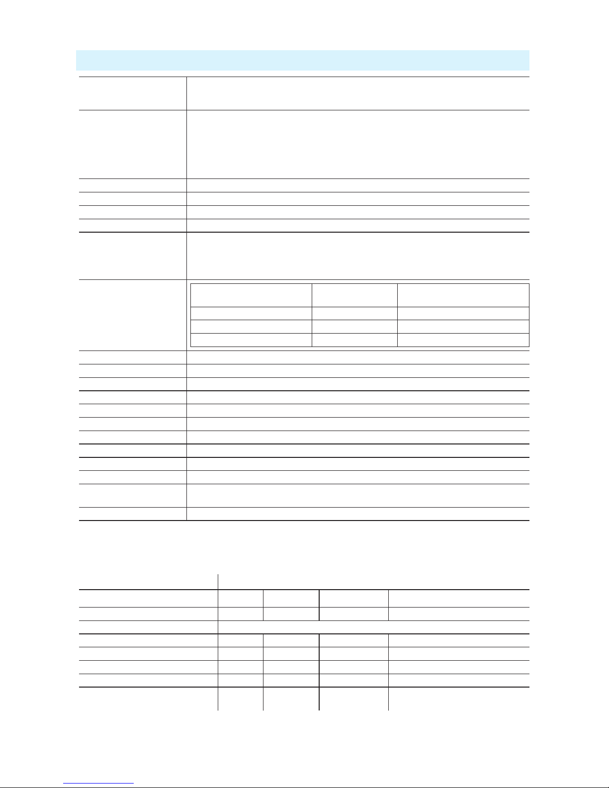
Specifications
A10 Digital Wireless
System
Frequency Range
470–694 MHz
Transmitter Switching
Bandwidth UK and International Models:
A10-TX-A (470–548 MHz)
A10-TX-B (518–608 MHz)
A10-TX-C (594–694 MHz)
Transmitters are tunable in 25 kHz steps.
U.S. Only Models:
See the A10-TX-US User Guide for more
information on these models.
A10-TX-AU (470–548 MHz)
A10-TX-BU (518–608 MHz)
Modulation Mode Audio Ltd. proprietary digital RF modulation
Digital Audio Codec Audio Ltd. proprietary, high-performance digital encoding algorithm
Audio Frequency Response 20 Hz–20 kHz
RF Output Power Low: 10 mW, Med: 20 mW, High: 50 mW, selectable
Audio Gain Control Lav setting: 0 dB to +40 dB, 1 dB increments
Line setting: -10 to 16 dB, 1 dB increments
Mic setting (w/ 20 dB pad): 16 to 40 dB, 1 dB increments
Mic setting (w/ no pad): 36 to 60 dB, 1 dB increments
Input Gain
Input Type
Input Impedance
(ohms)
Input Clipping Level
(minimum gain)
Lav 6.8k +6 dBu
Bal Mic - plus P48 and P12 2.5k +10 dBu (20 dB pad)
Bal Line 3k +24 dBu
Low Frequency Cut O, 40 Hz, 60 Hz, 80 Hz, 100 Hz, 200 Hz, user selectable
Input Limiter Analogue, (pre-A/D converter)
Input Type Microphone or line level, balanced or unbalanced
Bias and Phantom Power 5 V Bias, 12 V or 48 V phantom power
Menu and Controls OLED menu display, 3 button navigation
Recording File Format Audio Ltd. proprietary .mic data le, requires conversion to WAV le
microSD Card microSD, microSDHC, microSDXC
Timecode Clock 0.2 ppm accuracy, holds accurate clock for 6 hours without power
Privacy User settable 4-digit PIN, Audio Ltd. proprietary
Powering 2 x 1.5V LR6 AA size, lithium, NiMH, or alkaline
Operating Temperature
Range
-10 °C to +55 °C
Weight and Dimensions 104 g, 83 x 64 x 18 mm
Input Connector Wiring Diagram
The A10-TX LEMO input connector accepts numerous input types. Select the input type in the
Selection Menu before connecting an audio source.
LEMO Connection
Input Type pin-1 pin-2 pin-3 shell
Two-Wire Lavalier Microphone shield open audio/bias shield or open
Three-Wire Lavalier Microphone not compatible
Balanced Microphone XLR pin-3 XLR pin-2 XLR pin-1 XLR pin-1, shell optional
Balanced Line-Level XLR pin-3 XLR pin-2 XLR pin-1 XLR pin-1, shell optional
Unbalanced Microphone earth signal earth earth
Unbalanced Line-Level earth signal earth earth
Timecode earth LTC out of
A10-TX
LTC into A10-TX earth or open
ªPhantom power can be activated only when the shell of the LEMO-3 is connected to pin-3 of
the LEMO-3 connector.

- 16 -
A10-TX User Guide
Battery Runtime Chart
There are many factors that will alter run times, including the mic in use.
This section’s chart shows approximate battery runtime in minutes based on the listed operation.
Operation
Battery Type
NiMH (2450 mAHr) Alkaline Lithium (Energizer Ultimate)
recording only 18 hr 53 min 14 hr 26 min 33 hr 5 min
10 mW (RF Power Low) 8 hr 12 min 4 hr 7 min 12 hr 18 min
20 mW (RF Power Med) 7 hr 29 min 3 hr 56 min 11 hr 31 min
50 mW (RF Power High) 4 hr 33 min 2 hr 21 min 7 hr 57 min
recording only, 48 V 9 hr 47 min 6 hr 2 min 17 hr 44 min
50 mW, 48 V 3 hr 29 min 1 hr 33 min 6 hr 20 min
ªThe 48 V tests were run with a Schoeps CMIT Mini. Other settings used for tests to compile
the chart are: Low Cut O, Limiter On, 40 dB gain (for 48 V)/30 dB gain (for Lav), freshly
formatted 8G card (16 hr record time), Bluetooth On, Blue LED On, and Brightness set to 5.
Certifications
Industry Canada Conformity
EN: This device complies with Industry Canada RSS-210. Operation is subject to the following
two conditions: (1) this device may not cause interference, and (2) this device must accept any
interference, including interference that may cause undesired operation of the device.
FR :Le présent appareil est conforme aux CNR d’Industrie Canada applicables aux appareils
radio RSS-210. L’exploitation est autorisée aux deux conditions suivantes: (1) l’appareil ne doit
pas produire de brouillage, et (2) l’utilisateur de l’appareil doit accepter tout brouillage radioélec-
trique subi, même si le brouillage est susceptible d’en compromettre le fonctionnement.
FCC Conformity
The A10-TX transmitter complies with the following requirements:
FCC (Federal Communications Commission) Part 74
Operation is subject to the following two conditions:
(1) This device may not cause harmful interference, and
(2) This device must accept any interference received, including interference that may cause
undesired operations.
Changes or modication not expressly approved.
A10-TX frequency ranges supplied for use in USA.
A10-TX transmitters available for sale in the U. S. can tune over a switching bandwidth of up to
100 MHz. e frequency ranges are listed below:
• 470.1–547.9 MHz
• 518.1–607.9 MHz
ªFrequency range 608–614 MHz is forbidden for use in US.
ªWarning! Any modications or changes made to this device, unless explicitly approved by
Audio Ltd. may invalidate the authorisation of this device. Operation of an unauthorised

- 17 -
A10-TX User Guide
device is prohibited under Section 302 of the Communications act of 1934, as amended,
and Subpart 1 of Part 2 of Chapter 47 of the Code of Federal Regulations.
Minimize RF Exposure
To avoid the possibility of exceeding the FCC RF exposure limits, it is recommended that the
transmitter or attached microphone be kept at a minimum distance of 13 mm (0.5 inch) away
from the head or body during normal operation.

- 18 -
A10-TX User Guide
Frequency Tables
The A10-TX oers preselected frequencies based on channels and sub channels. Three sets of
frequencies are available based on either 6, 7, or 8 MHz channel bandwidth. Select the channel
bandwidth based on the geographic region where the unit is operating.
X Frequencies (6 MHz Per TV Channel)
The chart below shows all frequencies available for the A10 wireless system. Not all channels
are available on all transmitters.
Sub Channel
1 2 3 4 5 6 7 8 9 10 11 12 13 14 15
Channel
14 470.2 470.6 471 471.4 471.8 472.2 472.6 473 473.4 473.8 474.2 474.6 475 475.4 475.8
15 476.2 476.6 477 477.4 477.8 478.2 478.6 479 479.4 479.8 480.2 480.6 481 481.4 481.8
16 482.2 482.6 483 483.4 483.8 484.2 484.6 485 485.4 485.8 486.2 486.6 487 487.4 487.8
17 488.2 488.6 489 489.4 489.8 490.2 490.6 491 491.4 491.8 492.2 492.6 493 493.4 493.8
18 494.2 494.6 495 495.4 495.8 496.2 496.6 497 497.4 497.8 498.2 498.6 499 499.4 499.8
19 500.2 500.6 501 501.4 501.8 502.2 502.6 503 503.4 503.8 504.2 504.6 505 505.4 505.8
20 506.2 506.6 507 507.4 507.8 508.2 508.6 509 509.4 509.8 510.2 510.6 511 511.4 511.8
21 512.2 512.6 513 513.4 513.8 514.2 514.6 515 515.4 515.8 516.2 516.6 517 517.4 517.8
22 518.2 518.6 519 519.4 519.8 520.2 520.6 521 521.4 521.8 522.2 522.6 523 523.4 523.8
23 524.2 524.6 525 525.4 525.8 526.2 526.6 527 527.4 527.8 528.2 528.6 529 529.4 529.8
24 530.2 530.6 531 531.4 531.8 532.2 532.6 533 533.4 533.8 534.2 534.6 535 535.4 535.8
25 536.2 536.6 537 537.4 537.8 538.2 538.6 539 539.4 539.8 540.2 540.6 541 541.4 541.8
26 542.2 542.6 543 543.4 543.8 544.2 544.6 545 545.4 545.8 546.2 546.6 547 547.4 547.8
27 548.2 548.6 549 549.4 549.8 550.2 550.6 551 551.4 551.8 552.2 552.6 553 553.4 553.8
28 554.2 554.6 555 555.4 555.8 556.2 556.6 557 557.4 557.8 558.2 558.6 559 559.4 559.8
29 560.2 560.6 561 561.4 561.8 562.2 562.6 563 563.4 563.8 564.2 564.6 565 565.4 565.8
30 566.2 566.6 567 567.4 567.8 568.2 568.6 569 569.4 569.8 570.2 570.6 571 571.4 571.8
31 572.2 572.6 573 573.4 573.8 574.2 574.6 575 575.4 575.8 576.2 576.6 577 577.4 577.8
32 578.2 578.6 579 579.4 579.8 580.2 580.6 581 581.4 581.8 582.2 582.6 583 583.4 583.8
33 584.2 584.6 585 585.4 585.8 586.2 586.6 587 587.4 587.8 588.2 588.6 589 589.4 589.8
34 590.2 590.6 591 591.4 591.8 592.2 592.6 593 593.4 593.8 594.2 594.6 595 595.4 595.8
35 596.2 596.6 597 597.4 597.8 598.2 598.6 599 599.4 599.8 600.2 600.6 601 601.4 601.8
36 602.2 602.6 603 603.4 603.8 604.2 604.6 605 605.4 605.8 606.2 606.6 607 607.4 607.8
37 608.2 608.6 609 609.4 609.8 610.2 610.6 611 611.4 611.8 612.2 612.6 613 613.4 613.8
38 614.2 614.6 615 615.4 615.8 616.2 616.6 617 617.4 617.8 618.2 618.6 619 619.4 619.8
39 620.2 620.6 621 621.4 621.8 622.2 622.6 623 623.4 623.8 624.2 624.6 625 625.4 625.8
40 626.2 626.6 627 627.4 627.8 628.2 628.6 629 629.4 629.8 630.2 630.6 631 631.4 631.8
41 632.2 632.6 633 633.4 633.8 634.2 634.6 635 635.4 635.8 636.2 636.6 637 637.4 637.8
42 638.2 638.6 639 639.4 639.8 640.2 640.6 641 641.4 641.8 642.2 642.6 643 643.4 643.8
43 644.2 644.6 645 645.4 645.8 646.2 646.6 647 647.4 647.8 648.2 648.6 649 649.4 649.8
44 650.2 650.6 651 651.4 651.8 652.2 652.6 653 653.4 653.8 654.2 654.6 655 655.4 655.8
45 656.2 656.6 657 657.4 657.8 658.2 658.6 659 659.4 659.8 660.2 660.6 661 661.4 661.8
46 662.2 662.6 663 663.4 663.8 664.2 664.6 665 665.4 665.8 666.2 666.6 667 667.4 667.8
47 668.2 668.6 669 669.4 669.8 670.2 670.6 671 671.4 671.8 672.2 672.6 673 673.4 673.8
48 674.2 674.6 675 675.4 675.8 676.2 676.6 677 677.4 677.8 678.2 678.6 679 679.4 679.8
49 680.2 680.6 681 681.4 681.8 682.2 682.6 683 683.4 683.8 684.2 684.6 685 685.4 685.8
50 686.2 686.6 687 687.4 687.8 688.2 688.6 689 689.4 689.8 690.2 690.6 691 691.4 691.8
51 692.2 692.6 693 693.4 693.8 694.2 694.6 695 695.4 695.8 696.2 696.6 697 697.4 697.8

- 19 -
A10-TX User Guide
Y Frequencies (7 MHz Per TV Channel)
Sub Channels
1234567891011 12 13 14 15 16 17
Channels
22 485.3 485.7 486.1 486.5 486.9 487.3 487.7 488.1 488.5 488.9 489.3 489.7 490.1 490.5 490.9 491.3 491.7
23 492.3 492.7 493.1 493.5 493.9 494.3 494.7 495.1 495.5 495.9 496.3 496.7 497.1 497.5 497.9 498.3 498.7
24 499.3 499.7 500.1 500.5 500.9 501.3 501.7 502.1 502.5 502.9 503.3 503.7 504.1 504.5 504.9 505.3 505.7
25 506.3 506.7 507.1 507.5 507.9 508.3 508.7 509.1 509.5 509.9 510.3 510.7 511.1 511.5 511.9 512.3 512.7
26 513.3 513.7 514.1 514.5 514.9 515.3 515.7 516.1 516.5 516.9 517.3 517.7 518.1 518.5 518.9 519.3 519.7
27 520.3 520.7 521.1 521.5 521.9 522.3 522.7 523.1 523.5 523.9 524.3 524.7 525.1 525.5 525.9 526.3 526.7
28 527.3 527.7 528.1 528.5 528.9 529.3 529.7 530.1 530.5 530.9 531.3 531.7 532.1 532.5 532.9 533.3 533.7
29 534.3 534.7 535.1 535.5 535.9 536.3 536.7 537.1 537.5 537.9 538.3 538.7 539.1 539.5 539.9 540.3 540.7
30 541.3 541.7 542.1 542.5 542.9 543.3 543.7 544.1 544.5 544.9 545.3 545.7 546.1 546.5 546.9 547.3 547.7
31 548.3 548.7 549.1 549.5 549.9 550.3 550.7 551.1 551.5 551.9 552.3 552.7 553.1 553.5 553.9 554.3 554.7
32 555.3 555.7 556.1 556.5 556.9 557.3 557.7 558.1 558.5 558.9 559.3 559.7 560.1 560.5 560.9 561.3 561.7
33 562.3 562.7 563.1 563.5 563.9 564.3 564.7 565.1 565.5 565.9 566.3 566.7 567.1 567.5 567.9 568.3 568.7
34 569.3 569.7 570.1 570.5 570.9 571.3 571.7 572.1 572.5 572.9 573.3 573.7 574.1 574.5 574.9 575.3 575.7
35 576.3 576.7 577.1 577.5 577.9 578.3 578.7 579.1 579.5 579.9 580.3 580.7 581.1 581.5 581.9 582.3 582.7
36 583.3 583.7 584.1 584.5 584.9 585.3 585.7 586.1 586.5 586.9 587.3 587.7 588.1 588.5 588.9 589.3 589.7
37 590.3 590.7 591.1 591.5 591.9 592.3 592.7 593.1 593.5 593.9 594.3 594.7 595.1 595.5 595.9 596.3 596.7
38 597.3 597.7 598.1 598.5 598.9 599.3 599.7 600.1 600.5 600.9 601.3 601.7 602.1 602.5 602.9 603.3 603.7
39 604.3 604.7 605.1 605.5 605.9 606.3 606.7 607.1 607.5 607.9 608.3 608.7 609.1 609.5 609.9 610.3 610.7
40 611.3 611.7 612.1 612.5 612.9 613.3 613.7 614.1 614.5 614.9 615.3 615.7 616.1 616.5 616.9 617.3 617.7
41 618.3 618.7 619.1 619.5 619.9 620.3 620.7 621.1 621.5 621.9 622.3 622.7 623.1 623.5 623.9 624.3 624.7
42 625.3 625.7 626.1 626.5 626.9 627.3 627.7 628.1 628.5 628.9 629.3 629.7 630.1 630.5 630.9 631.3 631.7
43 632.3 632.7 633.1 633.5 633.9 634.3 634.7 635.1 635.5 635.9 636.3 636.7 637.1 637.5 637.9 638.3 638.7
44 639.3 639.7 640.1 640.5 640.9 641.3 641.7 642.1 642.5 642.9 643.3 643.7 644.1 644.5 644.9 645.3 645.7
45 646.3 646.7 647.1 647.5 647.9 648.3 648.7 649.1 649.5 649.9 650.3 650.7 651.1 651.5 651.9 652.3 652.7
46 653.3 653.7 654.1 654.5 654.9 655.3 655.7 656.1 656.5 656.9 657.3 657.7 658.1 658.5 658.9 659.3 659.7
47 660.3 660.7 661.1 661.5 661.9 662.3 662.7 663.1 663.5 663.9 664.3 664.7 665.1 665.5 665.9 666.3 666.7
48 667.3 667.7 668.1 668.5 668.9 669.3 669.7 670.1 670.5 670.9 671.3 671.7 672.1 672.5 672.9 673.3 673.7
49 674.3 674.7 675.1 675.5 675.9 676.3 676.7 677.1 677.5 677.9 678.3 678.7 679.1 679.5 679.9 680.3 680.7
50 681.3 681.7 682.1 682.5 682.9 683.3 683.7 684.1 684.5 684.9 685.3 685.7 686.1 686.5 686.9 687.3 687.7
51 688.3 688.7 689.1 689.5 689.9 690.3 690.7 691.1 691.5 691.9 692.3 692.7 693.1 693.5 693.9 694.3 694.7

- 20 -
A10-TX User Guide
Z Frequencies (8 MHz Per TV Channel)
Sub Channels
1234567891011 12 13 14 15 16 17 18 19 20
Channels
21 470.2 470.6 471.0 471.4 471.8 472.2 472.6 473.0 473.4 473.8 474.2 474.6 475.0 475.4 475.8 476.2 476.6 477.0 477.4 477.8
22 478.2 478.6 479.0 479.4 479.8 480.2 480.6 481.0 481.4 481.8 482.2 482.6 483.0 483.4 483.8 484.2 484.6 485.0 485.4 485.8
23 486.2 486.6 487.0 487.4 487.8 488.2 488.6 489.0 489.4 489.8 490.2 490.6 491.0 491.4 491.8 492.2 492.6 493.0 493.4 493.8
24 494.2 494.6 495.0 495.4 495.8 496.2 496.6 497.0 497.4 497.8 498.2 498.6 499.0 499.4 499.8 500.2 500.6 501.0 501.4 501.8
25 502.2 502.6 503.0 503.4 503.8 504.2 504.6 505.0 505.4 505.8 506.2 506.6 507.0 507.4 507.8 508.2 508.6 509.0 509.4 509.8
26 510.2 510.6 511.0 511.4 511.8 512.2 512.6 513.0 513.4 513.8 514.2 514.6 515.0 515.4 515.8 516.2 516.6 517.0 517.4 517.8
27 518.2 518.6 519.0 519.4 519.8 520.2 520.6 521.0 521.4 521.8 522.2 522.6 523.0 523.4 523.8 524.2 524.6 525.0 525.4 525.8
28 526.2 526.6 527.0 527.4 527.8 528.2 528.6 529.0 529.4 529.8 530.2 530.6 531.0 531.4 531.8 532.2 532.6 533.0 533.4 533.8
29 534.2 534.6 535.0 535.4 535.8 536.2 536.6 537.0 537.4 537.8 538.2 538.6 539.0 539.4 539.8 540.2 540.6 541.0 541.4 541.8
30 542.2 542.6 543.0 543.4 543.8 544.2 544.6 545.0 545.4 545.8 546.2 546.6 547.0 547.4 547.8 548.2 548.6 549.0 549.4 549.8
31 550.2 550.6 551.0 551.4 551.8 552.2 552.6 553.0 553.4 553.8 554.2 554.6 555.0 555.4 555.8 556.2 556.6 557.0 557.4 557.8
32 558.2 558.6 559.0 559.4 559.8 560.2 560.6 561.0 561.4 561.8 562.2 562.6 563.0 563.4 563.8 564.2 564.6 565.0 565.4 565.8
33 566.2 566.6 567.0 567.4 567.8 568.2 568.6 569.0 569.4 569.8 570.2 570.6 571.0 571.4 571.8 572.2 572.6 573.0 573.4 573.8
34 574.2 574.6 575.0 575.4 575.8 576.2 576.6 577.0 577.4 577.8 578.2 578.6 579.0 579.4 579.8 580.2 580.6 581.0 581.4 581.8
35 582.2 582.6 583.0 583.4 583.8 584.2 584.6 585.0 585.4 585.8 586.2 586.6 587.0 587.4 587.8 588.2 588.6 589.0 589.4 589.8
36 590.2 590.6 591.0 591.4 591.8 592.2 592.6 593.0 593.4 593.8 594.2 594.6 595.0 595.4 595.8 596.2 596.6 597.0 597.4 597.8
37 598.2 598.6 599.0 599.4 599.8 600.2 600.6 601.0 601.4 601.8 602.2 602.6 603.0 603.4 603.8 604.2 604.6 605.0 605.4 605.8
38 606.2 606.6 607.0 607.4 607.8 608.2 608.6 609.0 609.4 609.8 610.2 610.6 611.0 611.4 611.8 612.2 612.6 613.0 613.4 613.8
39 614.2 614.6 615.0 615.4 615.8 616.2 616.6 617.0 617.4 617.8 618.2 618.6 619.0 619.4 619.8 620.2 620.6 621.0 621.4 621.8
40 622.2 622.6 623.0 623.4 623.8 624.2 624.6 625.0 625.4 625.8 626.2 626.6 627.0 627.4 627.8 628.2 628.6 629.0 629.4 629.8
41 630.2 630.6 631.0 631.4 631.8 632.2 632.6 633.0 633.4 633.8 634.2 634.6 635.0 635.4 635.8 636.2 636.6 637.0 637.4 637.8
42 638.2 638.6 639.0 639.4 639.8 640.2 640.6 641.0 641.4 641.8 642.2 642.6 643.0 643.4 643.8 644.2 644.6 645.0 645.4 645.8
43 646.2 646.6 647.0 647.4 647.8 648.2 648.6 649.0 649.4 649.8 650.2 650.6 651.0 651.4 651.8 652.2 652.6 653.0 653.4 653.8
44 654.2 654.6 655.0 655.4 655.8 656.2 656.6 657.0 657.4 657.8 658.2 658.6 659.0 659.4 659.8 660.2 660.6 661.0 661.4 661.8
45 662.2 662.6 663.0 663.4 663.8 664.2 664.6 665.0 665.4 665.8 666.2 666.6 667.0 667.4 667.8 668.2 668.6 669.0 669.4 669.8
46 670.2 670.6 671.0 671.4 671.8 672.2 672.6 673.0 673.4 673.8 674.2 674.6 675.0 675.4 675.8 676.2 676.6 677.0 677.4 677.8
47 678.2 678.6 679.0 679.4 679.8 680.2 680.6 681.0 681.4 681.8 682.2 682.6 683.0 683.4 683.8 684.2 684.6 685.0 685.4 685.8
48 686.2 686.6 687.0 687.4 687.8 688.2 688.6 689.0 689.4 689.8 690.2 690.6 691.0 691.4 691.8 692.2 692.6 693.0 693.4 693.8
Channel Assignments by Region
Region AL Frequency Region
North America, South Korea, Taiwan, Philippines X
UK and Western Europe , Greenland, Asia, Africa Z
Australia and New Zealand Y
Japan X
Taiwan X
China X
For further information, contact Audio Ltd or your local distributor
Copyright © 2017 Audio Ltd. All rights reserved. | www.audioltd.com
7 Century Court, Tolpits Lane, Watford WD18 9RS, UK | info@audioltd.com
Table of contents
Other Audio Ltd. Transmitter manuals


Popular Transmitter manuals by other brands


Endress+Hauser
Endress+Hauser Proline 500 Brief operating instructions

Aurora
Aurora HT Series Protocol guide

Vivace
Vivace HART VTT10-FH INSTALLATION, OPERATION, CONFIGURATION AND MAINTENANCE MANUAL

M-system
M-system BVS instruction manual

Sony
Sony TMR-BR100 instructions

Newham London
Newham London Roger Touchscreen Mic user guide and troubleshooter

Lynx
Lynx yellobrik OTX 1410 quick reference

Martin Lehmann
Martin Lehmann TXRF24B4 operating instructions

Williams Sound
Williams Sound Personal PA PPA T36 Specifications

RKI Instruments
RKI Instruments 65-2445 Series Operator's manual

Extron electronics
Extron electronics PVT RGB D Plus Setup guide

MSA
MSA General Monitors S4100T instruction manual