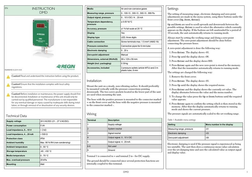
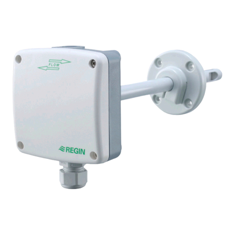
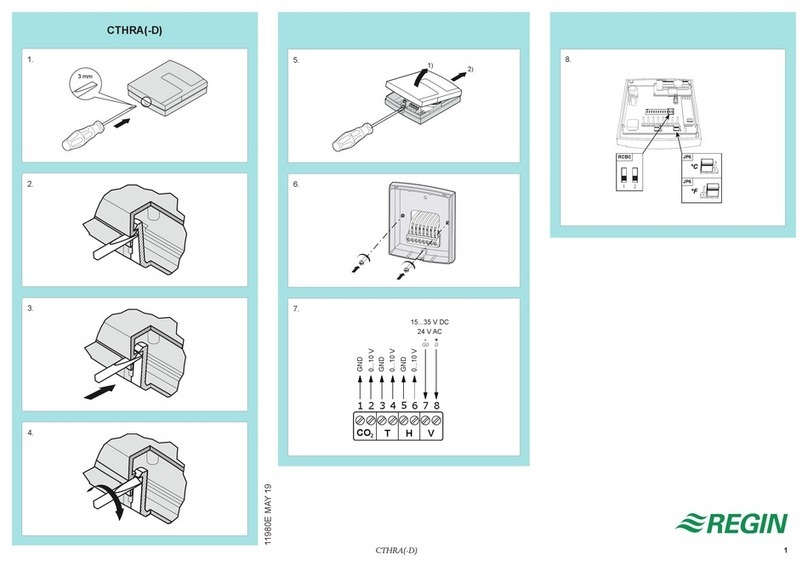
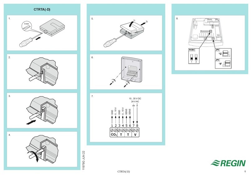
Regin PDTX C Series User manual

EN INSTRUCTION
PDTX…-C
REV. C, 2022-03-14
NNoottee!! More infor ation about the product configuration can be found in
the variable list, which is available for download fro www.regincontrols.
co
CCaauuttiioonn!! Read and understand the instruction before using the product.
CCaauuttiioonn!! Ensure that the installation co plies with local safety
regulations.
CCaauuttiioonn!! Before installation or aintenance, the power supply should first
be disconnected. Installation or aintenance of this unit should only be
carried out by qualified personnel. The anufacturer is not responsible
for any eventual da age or injury caused by inadequate skills during instal-
lation, or through re oval of or deactivation of any security devices.
Function
Presigo PDTX…-C is a range of pressure transmitters equipped with one
or two pressure sensors, two universal inputs, two universal outputs and
an RS48 port for Modbus communication. It operates as a Modbus
slave.
This range of pressure transmitters is especially well suited as distributed
I/O modules for air handling unit controllers. They are designed for easy
installation together with Regin’s Corrigo or EXOcompact controllers.
Technical data
Supply voltage 24 V AC/DC (21…27 V AC/DC)
Protection class IP54
Power consumption < 4 VA
Ambient humidity 0…95 % RH (non-condensing)
Ambient temperature -25…+50 °C
Working range, pressure 0…1250 / 0…2500 / 0…7500 Pa (factory setting)
0…12 / 0…25 / 0…75 mbar
0…127 / 0…254 / 0…764 mmH2O
0…5 / 0…10 / 0…30 inH2O
Working range, flow 0...65000 m3/h (factory setting)
0...31000 l/s
0...65000 Ft3/min
Cable glands 2 x M20 (cable diameter 5…12 mm)
1 x M16 (cable diameter 3.5…10 mm)
Max overvoltage ±18 V, on any terminal (not G and G0)
Electronic damping 0 s (0…120 s)
Accessories, included Two pressure outlets (straight) and 2 m plastic tube.
Art. no.: ANS-20
Dimensions, external
(WxHxD)
167 x (~130) x 46 mm
Pressure data
Media Air, non-combustible and non-aggressive gases
Annual deviation ±2 Pa (1250 Pa)
±4 Pa (2500 Pa)
±20 Pa (7500 Pa)
K-factor 5 (5…700)
Universal Input, UI1 and UI2
Universal inputs (UI) 2
Configuration AI (AI / DI), see specifications below
Configured as AI:
Analogue inputs (AI) 0…10 V (0…10 V / PT1000 / Ni1000-01)
Accuracy ± 1 % (0…10 V)
± 0.5 K (PT1000/Ni1000-01)
Measuring range,
temperature
-40…+60 °C
Configured as DI:
Digital input (DI) Potential-free contacts on / off (on = closed)
Output current 0.5 mA (max 2.5 V)
Universal Output, UO1 and UO2
Universal outputs (UO) 2
Configuration AO (AO / DO), see specifications below
Configured as AO:
Analogue outputs (AO) 0…10 V
Load impedance, 0...10 V Min. 10 kΩ
Accuracy ± 1 %
Configured as DO:
Configuration Mosfet outputs, 24 V AC or DC, 2 A continuous
Power output Max. 2A (total UO1 + UO2)
Co unication port data
Communication ports 1
Port type RS485
Supported protocols Modbus
Port isolation Non-isolated
Cable length Max 100 m
Models
Article Number of
sensors
Max overload
pressure (kPa)
Measuring range,
pressure (Pa)
PDTX12-C 1 25 0…1250
PDTX25-C 1 50 0…2500
PDTX75-C 1 120 0…7500
PDTX12-2-C 2 25 / 25 0…1250 (sensor 1) /
0…1250 (sensor 2)
PDTX25-2-C 2 50 / 50 0…2500 (sensor 1) /
0…2500 (sensor 2)
PDTX12S25-C 2 25 / 50 0…1250 (sensor 1) /
0…2500 (sensor 2)
PDTX12S75-C 2 25 / 120 0…1250 (sensor 1) /
0…7500 (sensor 2)
Presigo 1 (18)

Installation
The transmitter comes with one cable gland mounted and two loose. If
more than one cable is used, the other cable glands must be assembled to
the housing. Screw in the cable gland until the plastic knockout in the
housing snaps. Make sure to remove the plastic knockout completely.
Secure the cable gland. See Figure 1.
Figure 1 Installing the cable glands
1. Mount the transmitter horizontally or vertically on a stable,
vibration-free surface. If the unit is installed in a humid
environment, install it vertically with the cable gland edge of the unit
pointing down to allow moisture to escape.
2. Refer to the graphics below for wiring. Connect the communication
cable to terminals 3(A) and 4(B). Use the leftmost cable gland for
supply voltage and communication.
3. Power up the unit. Set the desired communication settings in the
menu (see Settings). Note that the transmitter uses the default
Modbus address = 1.
4. Refer to the Presigo PDTX…-C variable list for information on how
to access transmitter data.
. Let the unit warm up for 10 minutes, then perform a zero-set
calibration by pressing the push-button (see Handling).
6. Connect plastic tubes from the ventilation duct to the pressure
inlets.
The two leftmost inlets are connected to sensor 1 and the other two
to sensor 2. The inlet marked with '+' should be used to connect the
tube with the highest pressure and the inlet marked with '-' to the
one with the lowest pressure.
NNoottee!! A straight cut off nipple ust be used for ounting in the ventila-
tion duct.
For optimal measuring results, measuring points with turbulent air flow
should be avoided. Preferably, measuring should be performed at a
distance of 2 duct diameters before bends and branching and at 6 duct
diameters after bends and branching.
Wiring
Terminal Name Description
1 24 V (G) + Power supply 24 V AC/DC (Positive)
2 24 V (G0) - Power supply 24 V AC/DC (Negative/
Ground)
3 RS485 - A Communication A (-)
4 RS485 - B Communication B (+)
5 UO1 Universal output 1
6 24 V (G) + Internally connected to Terminal 1
7 GND Internally connected to Terminal 2
8 UO2 Universal output 2
9 UI1 Universal input 1
10 GND Internally connected to Terminal 2
11 UI2 Universal input 2
Use a shielded, twisted pair cable for RS48 communication. At high
risks of interference, a 120 Ω terminating resistor should be mounted at
each end of the communications circuit.
Wiring exa ples
Figure 2 UIx as 0…10 V input and UOx as 0…10 V output
Figure 3 UIx as digital input and UOx as digital output
+
12
-
ƟƟƟƟƟƟƟƟƟƟƟ
1234567891011
□□□□□□□□□□□
24V(G) +
24V(G0) -
RS485-A
RS485-B
UO1
24V(G) +
GND
UO2
UI1
GND
UI2
24VAC/DC
1 2 3 4 5 6 7 8 9 10 11
Sensor 1
Sensor 2 (when available)
0...10 V
+
-
GND
Status LEDs
RS485
Modbus
Push-button
Display
Joystick
0...10 V
A
B
Optional
1 2 3 4 5 6 7 8 9 10 11
Sensor 1
Sensor 2 (when available)
Status LEDs
Push-button
Display
Joystick
1 2 3 4 5 6 7 8 9 10 11
24VAC/DC
+
-
RS485
Modbus
Digital
Potential-free
A
B
Digital
Presigo 2 (18)

Figure 4 UIx as temperature input
Settings
Communication settings can be viewed and changed either via the menu
system or through Modbus communication. All other settings are
accessed and modified via Modbus. The joystick is used to manoeuvre
within the menu system (see Table 1).
Pressing the joystick briefly results in entering the viewing mode. When in
viewing mode all configured universal inputs and outputs, including
pressure and flow sensor values, can be viewed.
To enter the settings mode, press the joystick for at least s when the
display is inactive.
Table 1 Na igate the menu system
Joystick movements Action
○ (push in) Accept/select
Long press for settings mode (> 5 s)
Short press for viewing mode
↑ Select next
↓ Select previous
← Back / cancel
Getting started
How to view and modify settings in the menu system:
1. Enter into viewing or setting mode by pressing and releasing the
joystick (long or short press) when the display is inactive
2. Navigate through the different sub menus by moving the joystick up
or down
3. Select a sub menu by pressing and releasing the joystick
4. If in setting mode, select a value to modify by pressing and releasing
the joystick
. Change the value by moving the joystick up or down
6. Confirm the setting by pressing and releasing the joystick, or move
the joystick left to discard the changes
7. Move the joystick left to return to the previous menu
NNoottee!! The last configuration entered into the trans itter is always valid,
regardless of whether it was perfor ed using the enu syste or via
Modbus.
Viewing ode enu
Sub menu Description
P.# Pressure value
P.1 = sensor 1 / P.2 = sensor 2
F.# Flow value
F.1 = sensor 1 / F.2 = sensor 2
d.# UI: Value in digital mode
d.1 = UI1 / d.2 = UI2
u.# UI: Value in 0-10 V mode
u.1 = UI1 / u.2 = UI2
t.# UI: Value in temperature mode (°C)
t.1 = UI1 / t.2 = UI2
L.# UO: Value in digital mode
L.1 = UO1 / L.2 = UO2
U.# UO: Value in 0-10 V mode
U.1 = UO1 / U.2 = UO2
Two digits can be shown at a time in the display. Therefore, several
subsequent views are used to display a longer value. Example: A pressure
value of 23 0 Pa on sensor 1 is shown with three views, i.e. 1 P.1 2 23
3 0. The measuring unit for the displayed value is set via Modbus.
NNoottee!! The K-factor has to be set via Modbus to be able to view correct
flow values. Infor ation regarding flow calculation is found in the variable
list.
Settings ode enu
Settings related to the communication can be changed in the settings
mode menu via the display.
Sub menu Description
.A Modbus address (1-247), given as hexa-
decimal numbers (1-F7)
.b Modbus baud rate (see Table 2)
.C Modbus settings (see Table 3)
Table 2 Settings in the sub menu .b
Modbus baud rate Description
12 1200 bps
24 2400 bps
96 9600 bps (factory setting)
19 19200 bps
38 38400 bps
57 57600 bps
Table 3 Settings in the sub menu .C
Modbus settings Description
n1 8 bytes, 1 stop bit, no parity (factory setting)
n2 8 bytes, 2 stop bits, no parity
E1 8 bytes, 1 stop bit, even parity
E2 8 bytes, 2 stop bits, even parity
o1 8 bytes, 1 stop bit, odd parity
o2 8 bytes, 2 stop bits, odd parity
When the transmitter is connected to Regin’s Corrigo controller, it is
configured as an expansion unit. When configuring the unit for Regin's
freely programmable products the addressing can be set via Modbus. See
the Corrigo manual and the PDTX…-C variable list for more
information.
NNoottee!! All docu entation can be downloaded fro www.regincontrols.
co
Handling
LEDs
Three LEDs are available to show different states.
t
PT1000 or
Ni1000-DIN
1 2 3 4 5 6 7 8 9 10 11
Sensor 1
Sensor 2 (when available)
Status LEDs
Push-button
Display
Joystick
t
A
B
24VAC/DC
+
-
RS485
Modbus
Presigo 3 (18)

LEDs Description
Yellow RS485 data transmission indication
Red Global device status. Is activated when an error is
present (see the variable list for more details).
Green 1 Hz flash rate: Normal operation
5 Hz flash rate: Zero-set calibration is preformed
25 Hz flash rate: Factory reset is performed
Push-button
Action Description
Quick press Zero-set pressure calibration
The green LED will be flashing when the zero-set
operation has been made.
Long press (> 10 s) Reset to factory default settings
The green LEDs will be flashing during the opera-
tion. The unit will then reset and restart.
Zero-set pressure calibration
A short press on the push-button will zero-set calibrate the available
pressure sensors.
NNoottee!! Be sure to disconnect the pressure tubes before doing this. Let the
unit war up for 10 inutes before atte pting zero-set.
Factory reset
A long press on the push-button, more than 10 seconds, will perform a
factory restore of user defined settings. Table 4 displays some of the
settings that will be restored.
Table 4 Factory settings
Description Factory setting
Working range, pressure 0…1250 / 0…2500 / 0…7500 Pa
Working range, flow 0...65000 m3/h
UI 0…10 V
UO 0…10 V
Modbus address 1
Modbus setting 8 bytes, 1 stop bit, no parity
Modbus baud rate 9600 bps
K-factor 5
NNoottee!! All changes ade with Modbus will be reset when a factory reset
is ade.
This product carries the CE-mark. More information is available at
www.regincontrols.com.
Docu entation
All documentation can be downloaded from www.regincontrols.com
Contact
AB Regin, Box 116, 428 22 Kållered, Sweden
Tel: +46 31 720 02 00, Fax: +46 31 720 02 0
www.regincontrols.com, [email protected]
SE INSTRUKTION
PDTX…-C
NNootteerraa!! Mer infor ation o hur produkten konfigureras finns i variabe-
llistan, so är tillgänglig för nedladdning från www.regincontrols.co
OObbsseerrvveerraa!! Läs och förstå instruktionen innan du använder produkten.
OObbsseerrvveerraa!! Se till att installationen uppfyller lokala
säkerhetsbestä elser.
OObbsseerrvveerraa!! Innan installation eller underhåll åste atningsspänningen
först kopplas från. Installation eller underhåll av denna enhet ska endast ut-
föras av kvalificerad personal. Tillverkaren är inte ansvarig för eventuella
skador so orsakas av felaktig installation och/eller inaktivering eller bort-
tagning av säkerhetsanordningar.
Funktion
Presigo PDTX…-C är en serie trycktransmittrar med en eller två
tryckgivare, två universella ingångar, två universella utgångar och en
RS48 -port för Modbus-kommunikation. Den fungerar som en Modbus-
slav.
Denna serie trycktransmittrar passar mycket väl som distribuerade I/O-
moduler för luftbehandlingsenheter. De är utformade för enkel
installation med Regins regulatorer Corrigo eller EXOcompact.
Tekniska data
Matningsspänning 24 V AC/DC (21…27 V AC/DC)
Skyddsklass IP54
Strömförbrukning < 4 VA
Omgivande luftfuktighet 0…95 % RH (icke-kondenserande)
Omgivningstemperatur -25…+50 °C
Arbetsområde, tryck 0…1250 / 0…2500 / 0…7500 Pa (fabriksinställning)
0…12 / 0…25 / 0…75 mbar
0…127 / 0…254 / 0…764 mmH2O
0…5 / 0…10 / 0…30 inH2O
Arbetsområde, flöde 0...65000 m3/h (fabriksinställning)
0...31000 l/s
0...65000 Ft3/min
Kabelgenomföringar 2 x M20 (kabeldiameter 5…12 mm)
1 x M16 (kabeldiameter 3,5…10 mm)
Max spänning ±18 V, oberoende av plint (ej G och G0)
Elektronisk dämpning 0 s (0…120 s)
Tillbehör, inkluderade Två tryckuttag (raka) och 2 m plastslang. Art. no.:
ANS-20
Dimensioner, yttre
(BxHxD)
167 x (~130) x 46 mm
Tryckdata
Media Luft, icke-brännbara och icke-aggressiva gaser
Årlig avvikelse ±2 Pa (1250 Pa)
±4 Pa (2500 Pa)
±20 Pa (7500 Pa)
K-faktor 5 (5…700)
Universella ingångar, UI1 och UI2
Universella ingångar (UI) 2
Konfigurering AI (AI / DI), se specifikationer nedan
Konfigurerad som AI:
Analoga ingångar (AI) 0…10 V (0…10 V / PT1000 / Ni1000-01)
Noggrannhet ± 1 % (0…10 V)
± 0,5 K (PT1000/Ni1000-01)
Mätområde, temperatur -40…+60 °C
Konfigurerad som DI:
Presigo 4 (18)

Digital ingång (DI) Potentialfria kontakter på / av (på = sluten)
Utgångsström 0,5 mA (max 2,5 V)
Universella utgångar, UO1 och UO2
Universell utgång (UO) 2
Konfigurering AO (AO / DO), se specifikationer nedan
Konfigurerad som AO:
Analoga utgångar (AO) 0…10 V
Belastningsresistans,
0…10 V
Min. 10 kΩ
Noggrannhet ±1 %
Konfigurerad som DO:
Konfigurering Mosfetutgångar, 24 V AC eller DC, 2 A kontinuerligt
Matningsutgång Max. 2A (totalt UO1 + UO2)
Ko unikationsdata
Kommunikationsportar 1
Porttyp RS485
Stödda protokoll Modbus
Portisolering Ej isolerad
Kabellängd Max 100 m
Modeller
Artikel Antal givare Max övertryck
(kPa)
Mätområde, tryck (Pa)
PDTX12-C 1 25 0…1250
PDTX25-C 1 50 0…2500
PDTX75-C 1 120 0…7500
PDTX12-2-C 2 25 / 25 0…1250 givare 1) /
0…1250 (givare 2)
PDTX25-2-C 2 50 / 50 0…2500 (givare 1) /
0…2500 (givare 2)
PDTX12S25-C 2 25 / 50 0…1250 (givare 1) /
0…2500 (givare 2)
PDTX12S75-C 2 25 / 120 0…1250 (givare 1) /
0…7500 (givare 2)
Installation
Transmittern levereras med en monterad kabelgenomföring och två lösa.
Om mer än en kabel används måste de andra kabelgenomföringarna
monteras på kåpan. Skruva in kabelgenomföringen tills plastbiten i
kåpans vägg lossnar. Var noga med att ta bort plastbiten helt och hållet.
Skruva fast kabelgenomföringen ordentligt. Se Figur 1.
Figur 1 Installera kabelgenomföringarna
1. Montera transmittern horisontellt eller vertikalt på en stabil yta utan
vibrationer. Om enheten installeras i en fuktig miljö ska den
monteras vertikalt med kabelgenomföringarna pekande nedåt, så att
fukt kan komma ut.
2. För inkoppling, se nedanstående ritningar. Anslut
kommunikationskabeln till plint 3(A) och 4(B). Använd vänster
kabelgenomföring för matningsspänning och kommunikation.
3. Spänningssätt enheten. Gör de kommunikationsinställningar som
önskas i menyn (se Inställningar). Notera att transmittern använder
modbusaddress = 1 som standard.
4. Se variabellistan för Presigo PDTX…-C för mer information om hur
man får åtkomst till data i transmittern.
. Låt enheten värma upp i 10 minuter innan du genomför en
nollpunktskalibrering genom att trycka in tryckknappen (se
Hantering).
6. Anslut slangar från ventilationskanalen till tryckingångarna.
De två vänstra ingångarna ansluts till sensor 1 och de andra två till
sensor 2. Ingången märkt med '+' ska användas för att ansluta slangen
med det högsta trycket och ingången märkt med '-' till den med det
lägsta trycket.
NNootteerraa!! En rakt avskuren nippel åste användas för ontering i
ventilationskanalen.
För bästa möjliga mätresultat ska mätpunkter med turbulenta
luftströmmar undvikas. Helst ska mätning ske på ett avstånd av minst 2
kanaldiametrar före krökar och förgreningar och på 6 kanaldiametrar
efter krökar och förgreningar.
Inkoppling
Plint Namn Beskrivning
1 24 V (G) + Matningsspänning 24 V AC/DC (Plus)
2 24 V (G0) - Matningsspänning 24 V AC/DC (Mi-
nus/Jord)
3 RS485 - A Kommunikation A (-)
4 RS485 - B Kommunikation B (+)
5 UO1 Universell utgång 1
6 24 V (G) + Internt kopplad till plint 1
7 GND Internt kopplad till plint 2
8 UO2 Universell utgång 2
9 UI1 Universell ingång 1
10 GND Internt kopplad till plint 2
11 UI2 Universell ingång 2
Använd en skärmad, partvinnad kabel för RS48 -kommunikation. Vid
hög störningsrisk bör ett termineringsmotstånd på 120 Ω monteras i
vardera änden på kommunikationsslingan.
+
12
-
ƟƟƟƟƟƟƟƟƟƟƟ
1234567891011
□□□□□□□□□□□
24V(G) +
24V(G0) -
RS485-A
RS485-B
UO1
24V(G) +
GND
UO2
UI1
GND
UI2
Presigo 5 (18)

Inkopplingsexe pel
Figur 2 UIx som 0...10 V-ingång och UOx som 0…10 V-utgång
Figur 3 UIx som digital ingång och UOx som digital utgång
Figur 4 UIx som temperaturingång
Inställningar
Kommunikationsinställningar kan ses och ändras antingen via
menysystemet eller via Modbus-kommunikation. Alla andra inställningar
nås och ändras via Modbus. Joysticken används för att navigera inom
menyn (se Tabell 1).
Genom att kort trycka in joysticken når man visningsläget. I visningsläget
kan alla universella ingångar och utgångar avläsas, inklusive tryck- och
flödesgivarvärden.
För att komma in i inställningsläget, tryck in joysticken i minst s när
displayen är inaktiv.
Tabell 1 Na igera inom menysystemet
Joystick-rörelser Handling
○ (tryck in) Acceptera/välj
Långt tryck för inställningsläge (> 5 s)
Kort tryck för visningsläge
↑ Välj nästa
↓ Välj föregående
← Tillbaka / avbryt
Ko igång
Att visa och ändra inställningar i menysystemet:
1. Gå in i visnings- eller inställningsläge genom att trycka in och släppa
joysticken (lång eller kort intryckning) när displayen är inaktiv
2. Navigera genom de olika undermenyerna genom att flytta joysticken
upp eller ner
3. Välj en undermeny genom att trycka in och släppa joysticken
4. I inställningsläge, välj ett värde som ska ändras genom att trycka in
och släppa joysticken
. Ändra värdet genom att föra joysticken upp eller ner
6. Bekräfta inställningen genom att trycka in och släppa joysticken eller
för joysticken till vänster för att avfärda ändringarna
7. För joysticken till vänster för att återgå till föregående meny
NNootteerraa!! Den senast gjorda inställningen i trans ittern gäller alltid, oavsett
o den är gjord i enysyste et eller via Modbus.
Menyn för visningsläge
Undermeny Beskrivning
P.# Tryckområde
P.1 = sensor 1 / P.2 = sensor 2
F.# Flödesvärde
F.1 = sensor 1 / F.2 = sensor 2
d.# UI: Värde i digitalt läge
d.1 = UI1 / d.2 = UI2
u.# UI: Värde i 0…10 V-läge
u.1 = UI1 / u.2 = UI2
t.# UI: Värde i temperaturläge (°C)
t.1 = UI1 / t.2 = UI2
L.# UO: Värde i digitalt läge
L.1 = UO1 / L.2 = UO2
U.# UO: Värde i 0…10 V-läge
U.1 = UO1 / U.2 = UO2
Två siffror i taget kan visas i displayen. Därför används flera efterföljande
vyer för att visa ett längre värde. Exempel: Ett tryckvärde på 23 0 Pa på
sensor 1 visas med tre vyer, det betyder 1 P.1 2 23 3 0. Enheten för
det visade värdet ställs in via Modbus.
NNootteerraa!! K-faktorn åste ställas in via Modbus för att visa de rätta flödes-
värdena. Infor ation o flödesberäkning finns i variabellistan.
Menyn för inställningsläge
Inställningar relaterade till kommunikationen kan ändras i
inställningsmenyn via displayen.
24VAC/DC
1 2 3 4 5 6 7 8 9 10 11
Sensor 1
Sensor 2 (when available)
0...10 V
+
-
GND
Status LEDs
RS485
Modbus
Push-button
Display
Joystick
0...10 V
A
B
Optional
1 2 3 4 5 6 7 8 9 10 11
Sensor 1
Sensor 2 (when available)
Status LEDs
Push-button
Display
Joystick
1 2 3 4 5 6 7 8 9 10 11
24VAC/DC
+
-
RS485
Modbus
Digital
Potential-free
A
B
Digital
t
PT1000 or
Ni1000-DIN
1 2 3 4 5 6 7 8 9 10 11
Sensor 1
Sensor 2 (when available)
Status LEDs
Push-button
Display
Joystick
t
A
B
24VAC/DC
+
-
RS485
Modbus
Presigo 6 (18)

Undermeny Beskrivning
.A Modbus-adress (1-247), angett som hexa-
decimala tal (1-F7)
.b Modbus baud rate (se Tabell 2)
.C Modbusinställningar (se Tabell 3)
Tabell 2 Inställningar i undermenyn .b
Modbus baud rate Beskrivning
12 1200 bps
24 2400 bps
96 9600 bps (fabriksinställning)
19 19200 bps
38 38400 bps
57 57600 bps
Tabell 3 Inställningar i undermenyn .C
Modbusinställningar Beskrivning
n1 8 bitar, 1 stoppbit, ingen paritet
(fabriksinställning)
n2 8 bitar, 2 stoppbitar, ingen paritet
E1 8 bitar, 1 stoppbit, jämn paritet
E2 8 bitar, 2 stoppbitar, jämn paritet
o1 8 bitar, 1 stoppbit, udda paritet
o2 8 bitar, 2 stoppbitar, udda paritet
När transmittern ansluts till Regins regulator Corrigo konfigureras den
som en expansionsenhet. När enheten konfigureras för Regins fritt
programmerbara produkter kan adresseringen ändras via Modbus. Se
Corrigo-manualen och PDTX…-C variabellistan för mer information.
NNootteerraa!! Doku enten kan laddas ner från www.regincontrols.co
Hantering
Lysdioder
Det finns tre lysdioder för att visa olika tillstånd.
Lysdioder Beskrivning
Gul Indikering på RS485 dataöverföring
Röd Global enhetsstatus. Aktiveras när ett fel förekom-
mer (se variabellistan för mer information).
Grön 1 Hz blinkningshastighet: Normal drift
5 Hz blinkningshastighet: Nollpunktskalibrering
utförs
25 Hz blinkningshastighet: Fabriksåterställning
utförs
Tryckknapp
Handling Beskrivning
Snabb intryckning Nollpunktskalibrering av tryck
Den gröna lysdioden blinkar när nollpunktskalibrer-
ingen har utförts.
Lång intryckning (> 10 s) Återställ till fabriksinställningar
Den gröna lysdioden blinkar när åtgärden utförs.
Enheten kommer därefter att återställas och starta
om.
Nollpunktskalibrering tryck
Ett kort tryck på tryckknappen kommer att nollpunktskalibrera
tillgängliga trycksensorer.
NNootteerraa!! Ko ihåg att koppla från tryckanslutningarna innan åtgärden ut-
förs. Låt enheten vär a upp i 10 inuter innan ett försök till nollpunktska-
librering görs.
Fabriksåterställning
Ett långt tryck på tryckknappen, mer än 10 sekunder, utför en
fabriksåterställning av användardefinierade inställningar. Tabell 4 visar
några av inställningarna som återställs.
Tabell 4 Fabriksinställningar
Beskrivning Fabriksinställning
Arbetsområde, tryck 0…1250 / 0…2500 / 0…7500 Pa
Arbetsområde, flöde 0...65000 m3/h
UI 0…10 V
UO 0…10 V
Modbusadress 1
Modbusinställning 8 bitar, 1 stoppbit, ingen paritet
Modbus baud rate 9600 bps
K-faktor 5
NNootteerraa!! Alla ändringar so gjorts via Modbus återställs när en fabriksåter-
ställning görs.
Produkten är CE-märkt. Mer information finns på www.regincontrols.
com.
Doku entation
Dokumenten kan laddas ner från www.regincontrols.com
Kontakt
AB Regin, Box 116, 428 22 Kållered, Sverige
Tel: +46 31 720 02 00, Fax: +46 31 720 02 0
www.regincontrols.com, [email protected]
DE INSTALLATIONSANLEITUNG
PDTX…-C
HHiinnwweeiiss!! Weitere Infor ationen zur Produktkonfiguration finden Sie in
der Variablenliste, die unter www.regincontrols.de zu Download zur
Verfügung steht.
VVoorrssiicchhtt!! Lesen und beachten Sie die Installationsanleitung, bevor Sie das
Produkt verwenden.
VVoorrssiicchhtt!! Vergewissern Sie sich, dass die Installation den geltenden Si-
cherheitsvorschriften entspricht.
VVoorrssiicchhtt!! Vor der Installation oder Wartung uss zuerst die Stro ver-
sorgung unterbrochen werden. Die Installation oder Wartung dieses Ge-
räts darf nur von qualifizierten Fachkräften durchgeführt werden. Der
Hersteller haftet nicht für eventuelle Schäden oder Verletzungen, die
durch angelnde Fachkenntnisse bei der Installation oder durch das Ent-
fernen oder Deaktivieren von Sicherheitsvorrichtungen entstehen.
Funktion
Presigo PDTX…-C ist eine Reihe von Drucktransmittern, die mit einem
oder zwei Drucksensoren, zwei Universaleingängen, zwei
Universalausgängen und einer RS48 Schnittstelle für Modbus
Kommunikation ausgestattet sind. Das Gerät arbeitet als Modbus-Slave.
Presigo 7 (18)

Diese Reihe von Drucktransmittern eignet sich besonders gut als
dezentrale Ein-/Ausgangsmodule für Lüftungsregler. Sie wurden für eine
einfache Installation in Verbindung mit den Regin Reglern Corrigo oder
EXOcompact entwickelt.
Technische Daten
Versorgungsspannung 24 V AC/DC (21…27 V AC/DC)
Schutzart IP54
Leistungsaufnahme < 4 VA
Umgebungsfeuchte 0…95 % RH (nicht kondensierend)
Umgebungstemperatur -25…+50 °C
Arbeitsbereich, Druck 0…1250 / 0…2500 / 0…7500 Pa
(Werkseinstellung)
0…12 / 0…25 / 0…75 mbar
0…127 / 0…254 / 0…764 mmH2O
0…5 / 0…10 / 0…30 inH2O
Arbeitsbereich,
Durchfluss
0...65000 m3/h (Werkseinstellung)
0...31000 l/s
0...65000 Ft3/min
Kabelverschraubungen 2 x M20 (Kabeldurchmesser 5…12 mm)
1 x M16 (Kabeldurchmesser 3,5…10 mm)
Max. Überspannung ±18 V, an jeder Klemme (außer G und G0)
Elektronische Dämpfung 0 s (0…120 s)
Zubehör, inklusive Pro Sensor: Zwei Druckausgänge (gerade) und 2 m
Kunststoffrohr. Art.Nr: ANS-20
Abmessungen, außen (B
x H x T)
167 x (~130) x 46 mm
Druckangaben
Medien Luft, nicht brennbare und nicht aggressive Gase
Jährliche Abweichung ±2 Pa (1250 Pa)
±4 Pa (2500 Pa)
±20 Pa (7500 Pa)
K-Faktor 5 (5…700)
Universaleingang, UI1 und UI2
Universaleingänge (UI) 2
Konfiguration AI (AI / DI), siehe nachfolgende Angaben
Konfiguriert als AI:
Analogeingänge (AI) 0…10 V (0…10 V / PT1000 / Ni1000-01)
Genauigkeit ± 1 % (0…10 V)
± 0,5 K (PT1000/Ni1000-01)
Messbereich, Temperatur -40…+60 °C
Konfiguriert als DI:
Digitaleingang (DI) Potentialfreie Kontakte an / aus (an = geschlossen)
Ausgangsstrom 0,5 mA (max 2,5 V)
Universalausgang, UO1 und UO2
Universalausgänge (UO) 2
Konfiguration AO (AO / DO), siehe nachfolgende Angaben
Konfiguriert als AO:
Analogausgänge (AO) 0…10 V
Lastimpedanz, 0...10 V Min. 10 kΩ
Genauigkeit ± 1 %
Konfiguriert als DO:
Konfiguration Mosfet-Ausgänge, 24 V AC oder DC, 2 A
kontinuierlich.
Ausgang
Spannungsversorgung
Max. 2 A (gesamt UO1 + UO2)
Ko unikation über Datenschnittstelle
Kommunikationsschnitt-
stellen
1
Schnittstellentyp RS485
Unterstützte Protokolle Modbus
Schnittstellenisolation Nicht isoliert
Kabellänge Max. 100 m
Modelle
Artikel Anzahl Fühler Max. Überlas-
tungsdruck (kPa)
Messbereich,
Druck (Pa)
PDTX12-C 1 25 0…1250
PDTX25-C 1 50 0…2500
PDTX75-C 1 120 0…7500
PDTX12-2-C 2 25 / 25 0…1250 (Sensor 1) /
0…1250 (Sensor 2)
Artikel Anzahl Fühler Max. Überlas-
tungsdruck (kPa)
Messbereich,
Druck (Pa)
PDTX25-2-C 2 50 / 50 0…2500 (Sensor 1) /
0…2500 (Sensor 2)
PDTX12S25-C 2 25 / 50 0…1250 (Sensor 1) /
0…2500 (Sensor 2)
PDTX12S75-C 2 25 / 120 0…1250 (Sensor 1) /
0…7500 (Sensor 2)
Installation
Der Transmitter wird mit einer montierten und zwei zusätzlichen
Kabelverschraubungen geliefert. Wenn mehr als ein Kabel verwendet
wird, müssen die anderen Kabelverschraubungen an das Gehäuse
montiert werden. Schrauben Sie die Kabelverschraubung ein, bis der
Kunststoffausschnitt im Gehäuse herausbricht. Achten Sie darauf, dass
der Kunststoffausbruch vollständig entfernt wird. Sichern Sie die
Kabelverschraubung. Siehe Bild 1.
Bild 1 Montage der Kabel erschraubungen
1. Montieren Sie den Transmitter horizontal oder vertikal an einer
stabilen, vibrationsfreien Oberfläche. Wenn das Gerät in einer
feuchten Umgebung installiert wird, sollte es vertikal, mit den
Kabeleinführungen nach unten montiert werden, damit Feuchtigkeit
entweichen kann.
2. Informationen zur Verdrahtung finden Sie in den nachfolgenden
Grafiken. Verbinden Sie das Kommunikationskabel RS48 mit den
Klemmen 3(A) und 4(B). Verwenden Sie die Kabelverschraubung
ganz links für Versorgungsspannung und Kommunikation.
3. Schalten Sie das Gerät ein. Stellen Sie die gewünschten
Kommunikationseinstellungen im Menü ein (siehe Einstellungen).
Beachten Sie, dass der Transmitter die Standard-Modbus-Adresse =
1 verwendet.
Presigo 8 (18)

4. Informationen zum Zugriff auf die Daten des Transmitters finden
Sie in der Variablenliste Presigo PDTX…-C.
. Lassen Sie das Gerät 10 Minuten lang warmlaufen und führen Sie
dann durch Drücken der Taste eine Nullpunktkalibrierung durch
(siehe Bedienung).
6. Verbinden Sie die Kunststoffrohre vom Lüftungskanal mit den
Druckeingängen.
Die beiden Eingänge ganz links sind mit dem Sensor 1 und die
anderen beiden mit dem Sensor 2 verbunden. Der mit "+"
gekennzeichnete Eingang sollte verwendet werden, um das Rohr mit
dem höchsten Druck und der mit "-" gekennzeichnete Eingang mit
dem mit dem niedrigsten Druck zu verbinden.
HHiinnwweeiiss!! Für die Montage i Lüftungskanal uss ein gerade abgeschnitte-
ner Stutzen verwendet werden.
Für optimale Messergebnisse sollten Messstellen mit turbulenter
Luftströmung vermieden werden. Vorzugsweise sollte die Messung im
Abstand von 2 Kanaldurchmessern vor Bögen und Abzweigungen und in
einem Abstand von 6 Kanaldurchmessern nach Bögen und
Abzweigungen durchgeführt werden.
Verdrahtung
Klemme Name Beschreibung
1 24 V (G) + Spannungsversorgung 24 V AC/DC
(positiv)
2 24 V (G0) - Spannungsversorgung 24 V AC/DC
(negativ/Masse)
3 RS485 - A Kommunikation A (-)
4 RS485 - B Kommunikation A (+)
5 UO1 Universalausgang 1
6 24 V (G) + Intern verbunden mit Klemme 1
7 GND Intern verbunden mit Klemme 2
8 UO2 Universalausgang 2
Klemme Name Beschreibung
9 UI1 Universaleingang 1
10 GND Intern verbunden mit Klemme 2
11 UI2 Universaleingang 2
Verwenden Sie für die RS48 -Kommunikation ein geschirmtes Twisted-
Pair-Kabel. Bei hohem Störungsrisiko sollte an jedem Ende des
Netzwerkes ein Abschlusswiderstand von 120 Ω installiert werden.
Kle enbelegungsbeispiele
Bild 2 UIx als 0…10 V Eingang und UOx als 0…10 V Ausgang
Bild 3 UIx als Digitaleingang und UOx als Digitalausgang
Bild 4 UIx als Temperatureingang
Einstellungen
Kommunikationseinstellungen können entweder über das Menüsystem
oder über die Modbus-Kommunikation angezeigt und geändert werden.
Alle anderen Einstellungen werden über Modbus aufgerufen und
geändert. Der Joystick wird zum Bewegen innerhalb des Menüsystems
verwendet (siehe Tabelle 1).
+
12
-
ƟƟƟƟƟƟƟƟƟƟƟ
1234567891011
□□□□□□□□□□□
24V(G) +
24V(G0) -
RS485-A
RS485-B
UO1
24V(G) +
GND
UO2
UI1
GND
UI2
24VAC/DC
1 2 3 4 5 6 7 8 9 10 11
Sensor 1
Sensor 2 (when available)
0...10 V
+
-
GND
Status LEDs
RS485
Modbus
Push-button
Display
Joystick
0...10 V
A
B
Optional
1 2 3 4 5 6 7 8 9 10 11
Sensor 1
Sensor 2 (when available)
Status LEDs
Push-button
Display
Joystick
1 2 3 4 5 6 7 8 9 10 11
24VAC/DC
+
-
RS485
Modbus
Digital
Potential-free
A
B
Digital
t
PT1000 or
Ni1000-DIN
1 2 3 4 5 6 7 8 9 10 11
Sensor 1
Sensor 2 (when available)
Status LEDs
Push-button
Display
Joystick
t
A
B
24VAC/DC
+
-
RS485
Modbus
Presigo 9 (18)

Ein kurzer Druck auf den Joystick ruft den Anzeigemodus auf. Im
Anzeigemodus können alle konfigurierten Universalein- und -ausgänge,
einschließlich der Messwerte der Druck- und Volumenstromfühler,
angezeigt werden.
Um in den Einstellmodus zu gelangen, drücken Sie den Joystick
mindestens s lang, wenn das Display inaktiv ist.
Tabelle 1 Na igieren im Menüsystem
Joystick-Bewegungen Aktion
○ (Eindrücken) Bestätigen / Auswählen
Lang drücken für Einstellmodus (> 5 s)
Kurz drücken für Anzeigemodus
↑ Nächste auswählen
↓ Vorherige auswählen
← Zurück / Abbruch
Erste Schritte
Wie Sie Einstellungen im Menüsystem anzeigen und ändern können:
1. Wechseln Sie in den Anzeige- oder Einstellungsmodus, indem Sie
den Joystick drücken und loslassen (langes oder kurzes Drücken),
wenn die Anzeige inaktiv ist.
2. Navigieren Sie durch die verschiedenen Untermenüs, indem Sie den
Joystick nach oben oder unten bewegen.
3. Wählen Sie ein Untermenü durch Drücken und Loslassen des
Joysticks.
4. Wenn Sie sich im Einstellmodus befinden, wählen Sie einen zu
ändernden Wert durch Drücken und Loslassen des Joysticks.
. Ändern Sie den Wert, indem Sie den Joystick nach oben oder unten
bewegen.
6. Bestätigen Sie die Einstellung durch Drücken und Loslassen des
Joysticks oder bewegen Sie den Joystick nach links, um die
Änderungen zu verwerfen.
7. Bewegen Sie den Joystick nach links, um zum vorherigen Menü
zurückzukehren.
HHiinnwweeiiss!! Die letzte in den Trans itter eingegebene Konfiguration ist i -
er gültig, unabhängig davon, ob sie über das Menüsyste oder über
Modbus ausgeführt wurde.
Menü Anzeige odus
Untermenü Beschreibung
P.# Druckwert
P.1 = Fühler 1 / P.2 = Fühler 2
F.# Volumenstromwert
F.1 = Fühler 1 / F.2 = Fühler 2
d.# UI: Wert im Digitalmodus
d.1 = UI1 / d.2 = UI2
u.# UI: Wert im Modus 0-10 V
u.1 = UI1 / u.2 = UI2
t.# UI: Wert im Temperaturmodus (°C)
t.1 = UI1 / t.2 = UI2
L.# UO: Wert im Digitalmodus
L.1 = UO1 / L.2 = UO2
U.# UO: Wert im Modus 0-10 V
U.1 = UO1 / U.2 = UO2
Im Display können jeweils zwei Ziffern gleichzeitig angezeigt werden.
Daher werden mehrere aufeinanderfolgende Anzeigen verwendet, um
einen längeren Wert darzustellen. Beispiel: Ein Druckwert von 23 0 Pa
am Fühler 1 wird mit drei Anzeigen dargestellt, d.h. 1 P.1 2 23 3 0.
Die Maßeinheit für den angezeigten Wert wird über Modbus eingestellt.
HHiinnwweeiiss!! Der K-Faktor uss über Modbus eingestellt werden, u korrek-
te Volu enstro werte anzeigen zu können. Infor ationen zur Volu-
enstro berechnung finden Sie in der Variablenliste.
Menü Einstell odus
Einstellungen, die sich auf die Kommunikation beziehen, können im
Menü des Einstellmodus über das Display geändert werden.
Untermenü Beschreibung
.A Modbus-Adresse (1-247), angegeben als
Hexadezimalzahl (1-F7)
.b Modbus-Baudrate (siehe Tabelle 2)
.C Modbus-Einstellungen (siehe Tabelle 3)
Tabelle 2 Einstellungen im Untermenü .b
Modbus-Baudrate Beschreibung
12 1200 bps
24 2400 bps
96 9600 bps (Werkseinstellung)
19 19200 bps
Tabelle 2 Einstellungen im Untermenü .b (Forts.)
Modbus-Baudrate Beschreibung
38 38400 bps
57 57600 bps
Tabelle 3 Einstellungen im Untermenü .C
Modbus-Einstellungen Beschreibung
n1 8 Byte, 1 Stoppbit, keine Parität
(Werkseinstellung)
n2 8 Byte, 2 Stoppbits, keine Parität
E1 8 Byte, 1 Stoppbit, gerade Parität
E2 8 Byte, 2 Stoppbits, gerade Parität
o1 8 Byte, 1 Stoppbit, ungerade Parität
o2 8 Byte, 2 Stoppbits, ungerade Parität
Wenn der Transmitter mit einem Corrigo von Regin verbunden ist, wird
er als Erweiterungseinheit konfiguriert. Bei der Gerätekonfiguration für
die frei programmierbaren Produkte von Regin kann die Adressierung
über Modbus eingestellt werden. Weitere Informationen finden Sie im
Corrigo-Handbuch und in der PDTX…-C Variablenliste.
HHiinnwweeiiss!! Die gesa te Doku entation kann unter www.regincontrols.de
heruntergeladen werden.
Bedienung
LEDs
Für die Statusanzeige stehen drei LEDs zur Verfügung.
LEDs Beschreibung
Gelb Anzeige der RS485-Datenübertragung
Rot Globaler Gerätestatus. Wird aktiviert, wenn ein Feh-
ler vorliegt (weitere Details finden Sie in der
Variablenliste).
Grün 1 Hz Blinkfrequenz: Normalbetrieb
5 Hz Blinkfrequenz: Nullpunktkalibrierung wird
durchgeführt
25 Hz Blinkfrequenz: Zurücksetzen auf Werksein-
stellung wird durchgeführt
Presigo 10 (18)

Drucktaste
Aktion Beschreibung
Kurzer Tastendruck Nullpunktkalibrierung des Drucks
Die grüne LED blinkt, wenn der Nullpunkt eingestellt
wurde.
Langer Tastendruck (> 10
s)
Zurücksetzen auf die Werkseinstellungen
Die grünen LEDs blinken während des Vorgangs.
Das Gerät wird dann zurückgesetzt und neu
gestartet.
Nullpunktkalibrierung des Drucks
Durch einen kurzen Tastendruck werden die vorhandenen
Drucksensoren auf Null kalibriert.
HHiinnwweeiiss!! Stellen Sie sicher, dass die Druckschläuche vorher abgezogen
sind. Lassen Sie de Gerät ca. 10 Minuten Zeit u sich aufzuwär en, be-
vor Sie es zurücksetzen.
Zurücksetzen auf Werkseinstellung
Durch einen langen Tastendruck von mehr als 10 Sekunden werden die
benutzerdefinierten Einstellungen auf die Werkseinstellungen
zurückgesetzt. Tabelle 4 zeigt einige der Einstellungen an, die
wiederhergestellt werden.
Tabelle 4 Werkseinstellungen
Beschreibung Werkseinstellung
Arbeitsbereich, Druck 0…1250 / 0…2500 / 0…7500 Pa
Arbeitsbereich, Durchfluss 0...65000 m3/h
UI 0…10 V
UO 0…10 V
Modbus-Adresse 1
Modbus-Einstellungen 8 Byte, 1 Stoppbit, keine Parität
Modbus-Baudrate 9600 bps
K-Faktor 5
HHiinnwweeiiss!! Alle it Modbus vorgeno enen Änderungen werden zurück-
gesetzt, wenn eine Werksrückstellung durchgeführt wird.
Dieses Produkt trägt das CE-Zeichen. Weitere Informationen finden Sie
unter www.regincontrols.de.
Doku entation
Die gesamte Dokumentation kann unter www.regincontrols.de
heruntergeladen werden.
Kontakt
Regin Controls Deutschland GmbH, Haynauer Str. 49, 12249 Berlin,
Deutschland
Tel: +49 30 77 99 4-0, Fax: +49 30 77 99 4-13
www.regincontrols.de, [email protected]
FR INSTRUCTION
PDTX…-C
NNBB !! Pour plus d'infor ations sur la configuration produit et les listes de
variables, veuillez consulter le anuel, disponible sur le site www.regin-
controls.co
AAtttteennttiioonn !! Veuillez lire attentive ent l'instruction avant d'utiliser le
produit.
AAtttteennttiioonn !! Assurez-vous que l'installation est confor e aux nor es de
sécurité locales.
AAtttteennttiioonn !! Avant de procéder à l'installation ou à la aintenance de l'ap-
pareil, il convient de couper l'ali entation électrique. Les opérations d'ins-
tallation et de aintenance doivent être effectuées par un professionnel
qualifié. Le fabricant ne pourra être tenu responsable d'éventuels do a-
ges ou blessures causés par une installation défectueuse du produit, ou
par la désactivation des dispositifs de sécurité.
Fonction
Presigo PDTX…-C est une gamme de transmetteurs de pression simples
ou doubles, avec deux entrées universelles, deux sorties universelles et
un port RS48 pour la communication Modbus. Il communique en
esclave Modbus.
Cette gamme de transmetteurs est également prévue pour servir de
module IO pour des régulateurs de centrales de traitement d'air. Il est
conçu pour une utilisation simple avec les régulateurs Corrigo ou
EXOcompact.
Caractéristiques techniques
Alimentation 24 V AC/DC (21…27 V AC/DC)
Indice de protection IP54
Consommation < 4 VA
Humidité ambiante 0...90 % HR (sans condensation)
Température de
fonctionnement
-25…+50 °C
Plage de fonctionne-
ment, pression
0…1250 / 0…2500 / 0…7500 Pa (réglage usine)
0…12 / 0…25 / 0…75 mbar
0…127 / 0…254 / 0…764 mmH2O
0…5 / 0…10 / 0…30 inH2O
Plage de fonctionne-
ment, débit
0...65000 m3/h (réglage usine)
0...31000 l/s
0...65000 Ft3/min
Presses-étoupe 2 x M20 (diamètre câble 5…12 mm)
1 x M16 (diamètre câble 3.5…10 mm)
Surtension maximale ±18 V, toute borne (hors G et G0)
Lissage du signal 0 s (0…120 s)
Accessoires inclus Deux prises de pression (droites) et 2 m de tube
plastique. No Art.: ANS-20
Dimensions, externes
(LxHxP)
167 x (~130) x 46 mm
Pression no inale
Type de fluide Air, Gaz incombustibles non agressifs.
Déviation annuelle ±2 Pa (1250 Pa)
±4 Pa (2500 Pa)
±20 Pa (7500 Pa)
Facteur K 5 (5…700)
Entrées universelles, UI1 et UI2
Entrée universelle (UI) 2
Configuration AI (AI / DI), voir spécifications ci-dessous
Configuré en AI:
Entrées analogiques (AI) 0…10 V (0…10 V / PT1000 / Ni1000-01)
Précision ± 1 % (0…10 V)
± 0.5 K (PT1000/Ni1000-01)
Plage de mesure,
température
-40…+60 °C
Configuré en DI:
Entrée digitale (DI) Contacts secs on/off (On=fermé)
Courant de sortie 0.5 mA (max 2.5 V)
Presigo 11 (18)

Sortie universelle, UO1 et UO2
Sortie universelle (UO) 2
Configuration AO (AO / DO), voir spécifications ci-dessous
Configuré en AO:
Sorties analogiques (AO) 0…10 V
Impédance, 0...10 V Min. 10 kΩ
Précision ± 1 %
Configuré en DO:
Configuration Sorties Mosfet, 24 V AC ou DC, 2 A continu.
Sortie puissance Max. 2A (total UO1 + UO2)
Co unication
Ports de communication 1
Type de port RS485
Protocoles supportés Modbus
Isolation du port Non-isolé
Longueur du câble Max 100 m
Modèles
Article Nombre de
sondes
Surpression
maxi (kPa)
Plage de mesure,
pression (Pa)
PDTX12-C 1 25 0…1250
PDTX25-C 1 50 0…2500
PDTX75-C 1 120 0…7500
PDTX12-2-C 2 25 - 25 0…1250 (sonde 1) /
0…1250 (sonde 2)
PDTX25-2-C 2 50 / 50 0…2500 (sonde 1) /
0…2500 (sonde 2)
PDTX12S25-C 2 25 / 50 0…1250 (sonde 1) /
0…2500 (sonde 2)
PDTX12S75-C 2 25 / 120 0…1250 (sonde 1) /
0…7500 (sonde 2)
Installation
Le transmetteur est livré avec un presse étoupe monté et deux non
montés. Si plus d'un câble est utilisé, les autres resses-étoupe devront
être installés. Serrer le presse-étoupe jusqu'à ce que l'ouverture se fasse
dans le boitier. Retirer ensuite l'opercule. Serrer le presse-étoupe. Voir
Fig. 1.
Fig. 1 Instattlation des presses-étoupe.
1. Monter le transmetteur horizontalement ou verticalement sur une
surface stable et non soumise aux vibrations. Dans le cas d'une
installation en milieu humide, il est préférable de l'installer
verticalement afin de faciliter l'évacuation de l'humidité. vers les
presses-étoupe.
2. Se reporter aux schémas ci-dessous pour le raccordement. Raccorder
le câble de communication aux bornes 3(A) et 4(B). Utiliser l'entrée
la plus à gauche pour l'alimentation et la communication.
3. Mettre le régulateur sous tension. Régler les paramètres de
communication à partir du menu (voir Réglages). Note: Adresse
Modbus par défaut = 1
4. Se référer à la liste de variables Presigo PDTX…-C pour les données
transmises.
. Attendre 10 minutes et calibrer le zéro des sondes de pression à
l'aide du bouton (voir Fonctionnement).
6. Raccorder les tubes de pression aux entrées de l'appareil.
Les 2 prises de pression les plus à gauche correspondent à la sonde 1,
les autres à la sonde 2. Les entrées marquées '+' doivent être
connectées aux tubes mesurant la pression la plus élevée et les prises
marquées '-' aux tubes mesurant la pression la plus basse.
NNBB !! Des prises de pression rigides doivent être utilisés pour la esure de
pression en gaine.
Pour une lecture optimale, il est recommandé d'éviter la mesure de
pression en zone turbulente. Installer les prises de pression à une distance
de 2 x le diamètre de la gaine avant les coudes et les tés, et de 6 x le
diamètre après.
Raccorde ent
Borne Nom Description
1 24 V (G) + Alimentation 24 V AC/DC (positif)
2 24 V (G0) - Alimentation 24 V AC/DC (Négatif/
Commun)
3 RS485 - A Communication A (-)
4 RS485 - B Communication B (+)
5 UO1 Sortie universelle 1
6 24 V (G) + Raccordée en interne à la borne 1
7 GND Raccordée en interne à la borne 2
8 UO2 Sortie universelle 2
9 UI1 Entrée universelle
10 GND Raccordée en interne à la borne 2
11 UI2 Entrée universelle 2
Utiliser un câble, une paire torsadée avec écran pour la communication
RS48 . En cas de risque d'interférences, une résistance de 120 Ω doit
être installée à chaque extrémité du bus.
+
12
-
ƟƟƟƟƟƟƟƟƟƟƟ
1234567891011
□□□□□□□□□□□
24V(G) +
24V(G0) -
RS485-A
RS485-B
UO1
24V(G) +
GND
UO2
UI1
GND
UI2
Presigo 12 (18)

Exe ples de câblage
Fig. 2 UIx en entrée 0...10V et UOx en sortie 0...10V
Fig. 3 UIx en entrée digitale et UOx en sortie digitale
Fig. 4 UIx en entrée de température
Réglages
Les réglages de la communication peuvent être vus et modifiés via le
menu système ou via la communication Modbus. Tous les autres réglages
sont accessibles via Modbus. La manette permet de naviguer dans le
menu tel que décrit dans Tableau 1.
Un appui bref sur la manette permet d'entrer en Mode visualisation. En
mode visualisation, toutes les entrées et sorties universelles configurées
ainsi que les valeurs de pression et de débit peuvent être consultés.
Pour accéder au Mode réglage, appuyer sur la manette pendant s
lorsque l'écran est inactif.
Tableau 1 Na igation dans les menus
Mouvements de la
manette
Action :
○ (appui) Valider/sélectionner
Appui long pour le mode réglage (> 5 s)
Appui bref pour le mode visualisation
↑ Précedent
↓ Suivant
← Retour/annuler
Utilisation
Visulaliser et modifier des paramètres avec le menu système:
1. Entrer en mode visualisation ou en mode réglage par un appui (long
ou court) lorsque l'afficheur est inactif
2. Naviguer dans les sous menus à l'aide de la manette vers le haut et le
bas
3. Selectionner un menu par un appui bref sur la manette
4. En mode réglage, sélectionner une valeur par un appui bref
. Modifier la valeur avec le manette vers le haut ou vers le bas
6. Confirmer la modification par un appui bref, ou annuler la
modification par un mouvement vers la gauche.
7. Manette vers la gauche pour un retour à l'écran précédent
NNBB !! La dernière configuration entrée dans le trans etteur est toujours
valide, indépenda ent de la configuration précéde ent entrée via le
enu systè e ou le Modbus.
Menu visulalisation
Sous menu Description
P.# Pression
P.1 = Sonde 1 / P.2 = Sonde 2
F.# Débit
F.1 = Sonde 1 / F.2 = Sonde 2
d.# UI: Valeur en mode digital
d.1 = UI1 / d.2 = UI2
u.# UI: Valeur en mode 0-10 V
u.1 = UI1 / u.2 = UI2
t.# UI: Valeur en mode température °C
t.1 = UI1 / t.2 = UI2
L.# UO: Valeur en mode digital
L.1 = UO1 / L.2 = UO2
U.# UO: Valeur en mode 0-10 V
U.1 = UO1 / U.2 = UO2
L'écran possède 2 caractères. Pour visualiser des informations plus
longues, les valeurs sont divisées en plusieurs écrans. Exemple: Une
pression de 23 0 Pa sur la sonde 1 est lue en 3 différents écrans, i.e. 1
P.1 2 23 3 0. L'unité de mesure est sélectionnée en Modbus.
NNBB !! Le facteur K doit être réglé via Modbus afin que les débits soient cor-
recte ent affichés. Les infor ations relatives au calcul de débit sont dans
la liste des variables.
Menu réglages
Les réglages liés à la communication peuvent être modifiés via le mode
réglage de l'écran.
24VAC/DC
1 2 3 4 5 6 7 8 9 10 11
Sensor 1
Sensor 2 (when available)
0...10 V
+
-
GND
Status LEDs
RS485
Modbus
Push-button
Display
Joystick
0...10 V
A
B
Optional
1 2 3 4 5 6 7 8 9 10 11
Sensor 1
Sensor 2 (when available)
Status LEDs
Push-button
Display
Joystick
1 2 3 4 5 6 7 8 9 10 11
24VAC/DC
+
-
RS485
Modbus
Digital
Potential-free
A
B
Digital
t
PT1000 or
Ni1000-DIN
1 2 3 4 5 6 7 8 9 10 11
Sensor 1
Sensor 2 (when available)
Status LEDs
Push-button
Display
Joystick
t
A
B
24VAC/DC
+
-
RS485
Modbus
Presigo 13 (18)

Sous menu Description
.A Adresses Modbus (1-247), spécifiées
comme des nombres hexadécimaux (1-F7)
.b Vitesse de transmission Modbus Voir Ta-
bleau 2.
.C Réglages Modbus (voir Tableau 3)
Tableau 2 Réglages du sous menu .b
Vitesse de transmission Modbus Description
12 1200 bps
24 2400 bps
96 9600 bps (Réglage usine)
19 19200 bps
38 38400 bps
57 57600 bps
Tableau 3 Réglages du sous menu .c
Réglages Modbus Description
n1 8 bits, 1 bit de stop, pas de parité (Réglage
usine)
n2 8 bits, 2 bits de stop, pas de parité
E1 8 bits, 1 bit de stop, parité paire
E2 8 bits, 2 bits de stop, parité paire
o1 8 bits, 1 bit de stop, parité impaire
o2 8 bits, 2 bits de stop, parité impaire
Lorsque le transmetteur est raccordé à un régulateur Corrigo, il est
configuré comme unité d'extension. Lors de la configuration de
l'appareil pour des automates Regin, l'adressage peut être effectué via
Modbus. Pour plus de détails, voir le manuel du Corrigo ventilation et la
liste des variablesPDTX…-C .
NNBB !! Toute la docu entation est disponible sur notre site www.regin.fr .
Fonctionne ent
LEDs
Trois LEDs permettent d'indiquer différents états.
LEDs Description
Jaune Indication de la communication RS485
Rouge Status global de l'appareil. Elle est activée en cas
d'erreur (pour plus de détails, voir la liste des
variables)
Vert Clignotement 1 Hz Fonctionnement normal
Clignotement 5 Hz Calibrage du point zéro
Clignotement 25 Hz Réinitialisation paramètres
usine
Bouton poussoir
Action : Description
Appui bref Calibrage du point zéro
La LED verte clignote lorsque le calibrage du zéro
est effectué.
Appui long (>10s) Réinitialisation paramètres usine
Les LEDs vertes clignotent durant l'opération. Le
transmetteur se reinitialise et redémarre.
Calibrage du point zéro
Un appui bref sur le bouton poussoir lance le calibrage du zéro des
sondes de pression.
NNBB !! S'assurer que les prises de pression sont déconnectées avant l'opé-
ration. Attendre 10 inutes avant de calibrer le zéro des sondes de
pression.
Réinitialisation
Un appui long sur le bouton poussoir, plus de 10 secondes, lance la
réinitialisation aux paramètres usine. Tableau 4 indique les paramètres
restaurés.
Tableau 4 Réglages usine
Description Réglage d'usine
Plage de fonctionnement,
pression
0…1250 / 0…2500 / 0…7500 Pa
Plage de fonctionnement,
débit
0...65000 m3/h
UI 0…10 V
UO 0…10 V
Adresse Modbus 1
Réglages Modbus 8 bits, 1 bit de stop, pas de parité
Vitesse de transmission
Modbus
9600 bps
Facteur K 5
NNBB !! Tous les réglages effectués via Modbus sont effacés lors de la
réinitialisation.
Ce produit porte le marquage CE. Pour plus d'information, veuillez
consulter le site web www.regincontrols.com.
Docu entation
Toute la documentation est disponible sur notre site www.regin.fr .
Contact
Regin France, 32 rue Delizy, Hall 3, 93 00 Pantin
Tél : +33(0)1 41 83 02 02, Fax : +33(0)1 7 14 9 91
www.regin.fr, [email protected]
IT ISTRUZIONI PER L'INSTALLAZIONE
PDTX…-C
NNoottaa!! Ulteriori infor azioni sulla configurazione del prodotto sono dispo-
nibili nell'elenco delle variabili, scaricabile da www.industrietechnik.it
AAtttteennzziioonnee Pri a di utilizzare il prodotto, leggere e co prendere le
istruzioni.
AAtttteennzziioonnee Assicurarsi che l'installazione sia confor e alle nor e di sicu-
rezza locali.
AAtttteennzziioonnee Pri a dell'installazione o della anutenzione, l'ali entazione
deve essere scollegata per evitare scosse elettriche potenzial ente letali!
L'installazione o la anutenzione dell'unità deve essere eseguita solo da
personale qualificato. Il produttore non è responsabile di eventuali danni o
lesioni provocati da i perizia durante l'installazione o dalla ri ozione o di-
sattivazione dei dispositivi di sicurezza.
Funzione
Presigo PDTX…-C è una gamma di trasmettitori di pressione con uno o
due sensori di pressione, due ingressi universali, due uscite universali e
una porta RS48 per la comunicazione tramite Modbus. Il trasmettitore
funziona come unità slave in un sistema Modbus.
Questa gamma di trasmettitori di pressione è particolarmente adatta
all'utilizzo come moduli I/O distribuiti per i controllori delle unità di
Presigo 14 (18)

trattamento aria. Sono progettati per una facile installazione insieme ai
controllori Corrigo o EXOcompact di Regin.
Caratteristiche tecniche
Alimentazione 24 V AC/DC (21…27 V AC/DC)
Grado di protezione IP54
Potenza assorbita < 4 VA
Umidità ambiente 0…95 % UR (senza condensa)
Temperatura ambiente -25…+50 °C
Scala di lavoro,
pressione
0…1250 / 0…2500 / 0…7500 Pa (impostazione di
fabbrica)
0…12 / 0…25 / 0…75 mbar
0…127 / 0…254 / 0…764 mmH2O
0…5 / 0…10 / 0…30 inH2O
Scala di lavoro, flusso 0...65000 m3/h (impostazione di fabbrica)
0...31000 l/s
0...65000 Ft3/min
Pressacavo 2 x M20 (diametro cavo 5…12 mm)
1 x M16 (diametro cavo 3,5…10 mm)
Max sovratensione ±18 V, su qualsiasi terminale (non G e G0)
Smorzamento elettronico 0 s (0…120 s)
Accessori, inclusi Due attacchi per la pressione e tubo in plastica di 2
m. Codice art.: ANS-20
Dimensioni, esterne
(LxPxA)
167 x (~130) x 46 mm
Dati pressione
Fluido Aria, gas non combustibili e non aggressivi
Deviazione annuale ±2 Pa (1250 Pa)
±4 Pa (2500 Pa)
±20 Pa (7500 Pa)
Fattore K 5 (5…700)
Ingresso universale, UI1 and UI2
Ingressi universali (UI) 2
Configurazione AI (AI / DI), vedere le specifiche di seguito
Configurato come AI:
Ingressi analogici (AI) 0…10 V (0…10 V / PT1000 / Ni1000-01)
Precisione ± 1 % (0…10 V)
± 0,5 K (PT1000/Ni1000-01)
Scala di temperatura -40…+60 °C
Configurato come DI:
Ingressi digitali (ID) Contatti liberi da potenziale on/off (on = chiuso)
Corrente di uscita 0,5 mA (max 2,5 V)
Uscita universale, UO1 e UO2
Uscite universali 2
Configurazione AO (AO / DO), vedere le specifiche di seguito
Configurato come AO:
Uscite analogiche (AO) 0...10 V
Resistenza di carico, 0…
10 V
Min. 10 kΩ
Precisione ± 1 %
Configurato come DO:
Configurazione Uscite Mosfet, 24 V AC o DC, 2 A continui
Uscita di alimentazione Max. 2A (totale UO1 + UO2)
Dati di co unicazione
Porte di comunicazione 1
Tipo di porta RS485
Protocolli supportati Modbus
Porta isolata Non isolata
Lunghezza del cavo Max 100 m
Modelli
Articolo Numero di
sensori
Max pressione di
sovraccarico
(kPa)
Campo di misura,
pressione (Pa)
PDTX12-C 1 25 0…1250
PDTX25-C 1 50 0…2500
PDTX75-C 1 120 0…7500
PDTX12-2-C 2 25 / 25 0…1250 (sensore 1) /
0…1250 (sensore 2)
PDTX25-2-C 2 50 / 50 0…2500 (sensore 1) /
0…2500 (sensore 2)
PDTX12S25-C 2 25 / 50 0…1250 (sensore 1) /
0…2500 (sensore 2)
PDTX12S75-C 2 25 / 120 0…1250 (sensore 1) /
0…7500 (sensore 2)
Installazione
Il trasmettitore viene fornito con un pressacavo montato e due sciolti. Se
viene utilizzato più di un cavo, gli altri pressacavi devono essere
assemblati alla custodia. Avvitare il pressacavo finché il foro in plastica
nella custodia scatta. Assicurasi di rimuoverlo completamente. Vedi Fig.
1.
Fig. 1 Installazione dei pressaca i
1. Montare il trasmettitore orizzontalmente o verticalmente su una
superficie stabile e priva di vibrazioni. Se l'unità è installata in un
ambiente umido, installarlo in verticale con il bordo pressacavo
dell'unità verso il basso per permettere all'umidità di fuoriuscire.
2. Fare riferimento alle immagini di seguito per il cablaggio. Collegare il
cavo di comunicazione ai morsetti 3(A) e 4(B). Utilizzare il passaca-
vo più a sinistra per la tensione di alimentazione e la comunicazione.
3. Accendere l'unità. Stabilire le impostazioni di comunicazione
desiderate nel menu (vedi Impostazioni). Tenere presente che il
trasmettitore utilizza l'indirizzo Modbus predefinito = 1.
4. Fare riferimento all'elenco variabili del PresigoPDTX…-C per
informazioni su come accedere ai dati del trasmettitore.
. Lasciare che l'unità si avvii per 10 minuti, quindi eseguire la
calibrazione dello zero, premendo il pulsante (vedi Gestione).
6. Collegare i tubi in plastica dal condotto di ventilazione agli ingressi
di pressione.
I due ingressi più a sinistra sono collegati al sensore 1 e gli altri due al
sensore 2. L'ingresso contrassegnato con '+' deve essere utilizzato per
collegare il tubo con la pressione più alta e l'ingresso contrassegnato
con '-' a quello con la pressione più bassa.
+
12
-
Presigo 15 (18)

NNoottaa!! Per il ontaggio nel condotto di ventilazione è necessario utilizzare
un raccordo con un taglio diritto.
Per ottenere risultati di misurazione ottimali, evitare punti di
misurazione con flusso d'aria turbolento. La misurazione deve
prefibilmente essere eseguita a una distanza di 2 diametri di condotto,
prima di curve e diramazioni e a 6 diametri di condotto dopo curve e
diramazioni.
Cablaggio
Morsetto Nome Descrizione
1 24 V (G) + Alimentazione 24 V AC/DC (Positivo)
2 24 V (G0) - Alimentazione 24 V AC/DC (Negativo/
Terra)
3 RS485 - A Comunicazione A (-)
4 RS485 - B Comunicazione B (+)
5 UO1 Uscita universale 1
6 24 V (G) + Collegato internamente al Morsetto 1
7 GND Collegato internamente al Morsetto 2
8 UO2 Uscita universale 2
9 UI1 Ingresso universale 1
10 GND Collegato internamente al Morsetto 2
11 UI2 Ingresso universale 2
Utilizzare un cavo schermato a doppino intrecciato per la comunicazione
RS48 . In caso di elevato rischio di interferenza, montare una resistenza
di terminazione da 120 Ω a ciascuna estremità della linea di
comunicazione.
Ese pi di cablaggio
Fig. 2 UIx come ingresso 0…10 V e UOx come uscita 0…10 V
Fig. 3 UIx come ingresso digitale e UOx come uscita digitale
Fig. 4 UIx come ingresso della temperatura
I postazioni
Le impostazioni di comunicazione possono essere visualizzate e
modificate tramite il sistema di menu o tramite Modbus. Tutte le altre
impostazioni sono accessibili e modificabili tramite Modbus. Il joystick
viene utilizzato per spostarsi all'interno del sistema dei menu (vedi
Tabella 1).
Premendo brevemente il joystick si accede alla modalità di
visualizzazione. In modalità di visualizzazione è possibile visualizzare
tutti gli ingressi e le uscite universali configurati, inclusi i valori del
sensore di pressione e flusso.
Per accedere alla modalità impostazioni, premere il joystick per almeno s
quando il display è inattivo.
Tabella 1 Na igare nel sistema a menu
Movimenti
del joystick
Azione
○ (premere) Accetta/seleziona
Premere a lungo per la modalità impostazioni (> 5s)
Premere brevemente per la modalità di visualizzazione
↑ Seleziona successivo
↓ Seleziona precedente
← Indietro / Annulla
Utilizzo
Come visualizzare e modificare le impostazioni nel sistema di menu:
ƟƟƟƟƟƟƟƟƟƟƟ
1234567891011
□□□□□□□□□□□
24V(G) +
24V(G0) -
RS485-A
RS485-B
UO1
24V(G) +
GND
UO2
UI1
GND
UI2
24VAC/DC
1 2 3 4 5 6 7 8 9 10 11
Sensor 1
Sensor 2 (when available)
0...10 V
+
-
GND
Status LEDs
RS485
Modbus
Push-button
Display
Joystick
0...10 V
A
B
Optional
1 2 3 4 5 6 7 8 9 10 11
Sensor 1
Sensor 2 (when available)
Status LEDs
Push-button
Display
Joystick
1 2 3 4 5 6 7 8 9 10 11
24VAC/DC
+
-
RS485
Modbus
Digital
Potential-free
A
B
Digital
t
PT1000 or
Ni1000-DIN
1 2 3 4 5 6 7 8 9 10 11
Sensor 1
Sensor 2 (when available)
Status LEDs
Push-button
Display
Joystick
t
A
B
24VAC/DC
+
-
RS485
Modbus
Presigo 16 (18)

1. Entrare in modalità visualizzazione o impostazione premendo e
rilasciando il joystick (pressione lunga o breve) quando il display è
inattivo
2. Navigare attraverso i diversi sottomenu spostando il joystick su o giù
3. Selezionare un sottomenu premendo e rilasciando il joystick
4. Se in modalità impostazione, selezionare un valore da modificare
premendo e rilasciando il joystick
. Modificare il valore spostando il joystick su o giù
6. Confermare l'impostazione premendo e rilasciando il joystick,
oppure spostando il joystick a sinistra per annullare le modifiche
7. Spostare il joystick a sinistra per tornare al menu precedente
NNoottaa!! L'ulti a configurazione inserita nel tras ettitore è se pre valida,
indipendente ente dal fatto che sia stata eseguita tra ite il siste a di e-
nu o tra ite Modbus.
Menu odalità di visualizzazione
Sottomenu Descrizione
P.# Valore di pressione
P.1 = sensore 1 / P.2 = sensore 2
F.# Valore di flusso
F.1 = sensore 1 / F.2 = sensore 2
d.# UI: Valore in modalità digitale
d.1 = UI1 / d.2 = UI2
u.# UI: Valore in modalità 0-10 V
u.1 = UI1 / u.2 = UI2
t.# UI: Valore in temperatura (º C)
t.1 = UI1 / t.2 = UI2
L.# UO: Valore in modalità digitale
L.1 = UO1 / L.2 = UO2
U.# UO: Valore in modalità 0-10 V
U.1 = UO1 / U.2 = UO2
Sul display possono essere visualizzate due cifre alla volta. Di
conseguenza, per visualizzare un valore più lungo vengono utilizzate
diverse viste successive. Esempio: Un valore di pressione di 23 0 Pa sul
sensore 1 viene mostrato con tre viste, ad es. 1 P.1 2 23 3 0. L'unità
di misura del valore visualizzato è impostata tramite Modbus.
NNoottaa!! ll fattore K deve essere i postato tra ite Modbus per poter visua-
lizzare i valori di flusso corretti. Le infor azioni relative al calcolo della
portata si trovano nell'elenco delle variabili.
Menu odalità I postazioni
Le impostazioni relative alla comunicazione possono essere modificate
nel menu della modalità impostazioni tramite il display.
Sottomenu Descrizione
.A Indirizzo Modbus (1-247), indicato come
numeri esadecimali (1-F7)
.b Baud rate Modbus (vedi Tabella 2)
.C Impostazioni Modbus (vedi Tabella 3)
Tabella 2 Impostazioni nel sottomenu .b
Baud rate Modbus Descrizione
12 1200 bps
24 2400 bps
96 9600 bps (impostazione di fabbrica)
19 19200 bps
38 38400 bps
57 57600 bps
Tabella 3 Impostazioni nel sottomenu .C
Impostazioni Modbus Descrizione
n1 8 byte, 1 bit di stop, nessuna parità (impo-
stazione di fabbrica)
n2 8 byte, 2 bit di stop, nessuna parità
E1 8 byte, 1 bit di stop, parità pari
E2 8 byte, 2 bit di stop, parità pari
o1 8 byte, 1 bit di stop, parità dispari
o2 8 byte, 2 bit di stop, parità dispari
Quando il trasmettitore è collegato al controllore Corrigo di Regin, è
configurato come unità di espansione. Quando si configura l'unità per i
prodotti liberamente programmabili di Regin è possibile impostare
l'indirizzamento tramite Modbus. Vedi il manuale Corrigo e l'elenco
delle variabili del PDTX…-C per ulteriori informazioni.
NNoottaa!! La docu entazione può essere scaricata da
www.industrietechnik.it
Gestione
LED
Sono disponibili tre LED per mostrare diverse modalità.
LED Descrizione
Giallo Indicazione trasmissione dati RS485
Rosso Stato generale del dispositivo. Si attiva quando è
presente un errore (consultare l'elenco delle variabi-
li per maggiori dettagli).
Verde Lampeggio 1 Hz: Esercizio normale:
Lampeggio 5 Hz: Viene eseguita la calibrazione del-
lo zero.
Lampeggio 25 Hz: Viene eseguito il reset di
fabbrica
Pulsante
Azione Descrizione
Pressione breve Calibrazione dello zero della pressione
Il LED verde lampeggia quando è stata effettuata
l'operazione di azzeramento.
Pressione lunga (> 10 s) Ripristina le impostazioni predefinite di fabbrica
I LED verdi lampeggeranno durante l'operazione.
L'unità verrà quindi ripristinata e riavviata.
Calibrazione dello zero della pressione
Una breve pressione sul pulsante azzererà i sensori di pressione
disponibili.
NNoottaa!! Assicurarsi di scollegare i tubi di pressione pri a dell'operazione.
Lasciare che l'unità si avvii per 10 inuti pri a di esseguire l'operazione di
azzera ento.
Reset di fabbrica
Una pressione prolungata del pulsante, per più di 10 secondi, eseguirà un
ripristino di fabbrica delle impostazioni definite dall'utente. La Tabella 4
visualizza alcune delle impostazioni che verranno ripristinate.
Tabella 4 Impostazioni di fabbrica
Descrizione Impostazione di fabbrica
Scala di lavoro, pressione 0…1250 / 0…2500 / 0…7500 Pa
Scala di lavoro, flusso 0...65000 m3/h
UI 0...10 V
UO 0...10 V
Indirizzo Modbus 1
Impostazioni Modbus 8 byte, 1 bit di stop, nessuna parità
Baud rate Modbus 9600 bps
Fattore K 5
NNoottaa!! Tutte le odifiche apportate con Modbus vengono resettate quan-
do si effettua un reset di fabbrica.
Presigo 17 (18)

Questo prodotto è provvisto di marchio CE. Ulteriori informazioni sono
disponibili su www.industrietechnik.it
Docu entazione
La documentazione può essere scaricata da www.industrietechnik.it
Contatti
AB Industrietechnik SRL, Via Julius-Durst-Str. 0, I-39042 Bressanone
(BZ)
Tel: +390472830626, Fax: +390472831840
www.industrietechnik.it, [email protected]
Presigo 18 (18)
Table of contents
Languages:
Other Regin Transmitter manuals
Popular Transmitter manuals by other brands

Jamara
Jamara CCX Pro Instruction

Dwyer Instruments
Dwyer Instruments CDTV Series Specifications-installation and operating instructions

Analytical Technology
Analytical Technology Q45 manual

AMIMON
AMIMON CONNEX ProSight Installation and operation guide

Mantracourt
Mantracourt T24-ACMm user manual

Gonnheimer Elektronic
Gonnheimer Elektronic D122.T user manual