Contents
Introduction ..............................................................................................................................................................................3
Our assumptions about you ..................................................................................................................................................3
Notice to novice users ....................................................................................................................................................3
What this manual covers ......................................................................................................................................................3
How this manual is organized................................................................................................................................................3
Where to go for further assistance........................................................................................................................................3
Minimum Requirements ..........................................................................................................................................................4
Tasks the Software Performs ..................................................................................................................................................4
System features the software monitors and controls ..........................................................................................................4
System features the software monitors (but does not control) ............................................................................................4
Software tools........................................................................................................................................................................4
Installing the Hardware............................................................................................................................................................5
Master and slave receivers....................................................................................................................................................5
General instructions for hardware installation ......................................................................................................................5
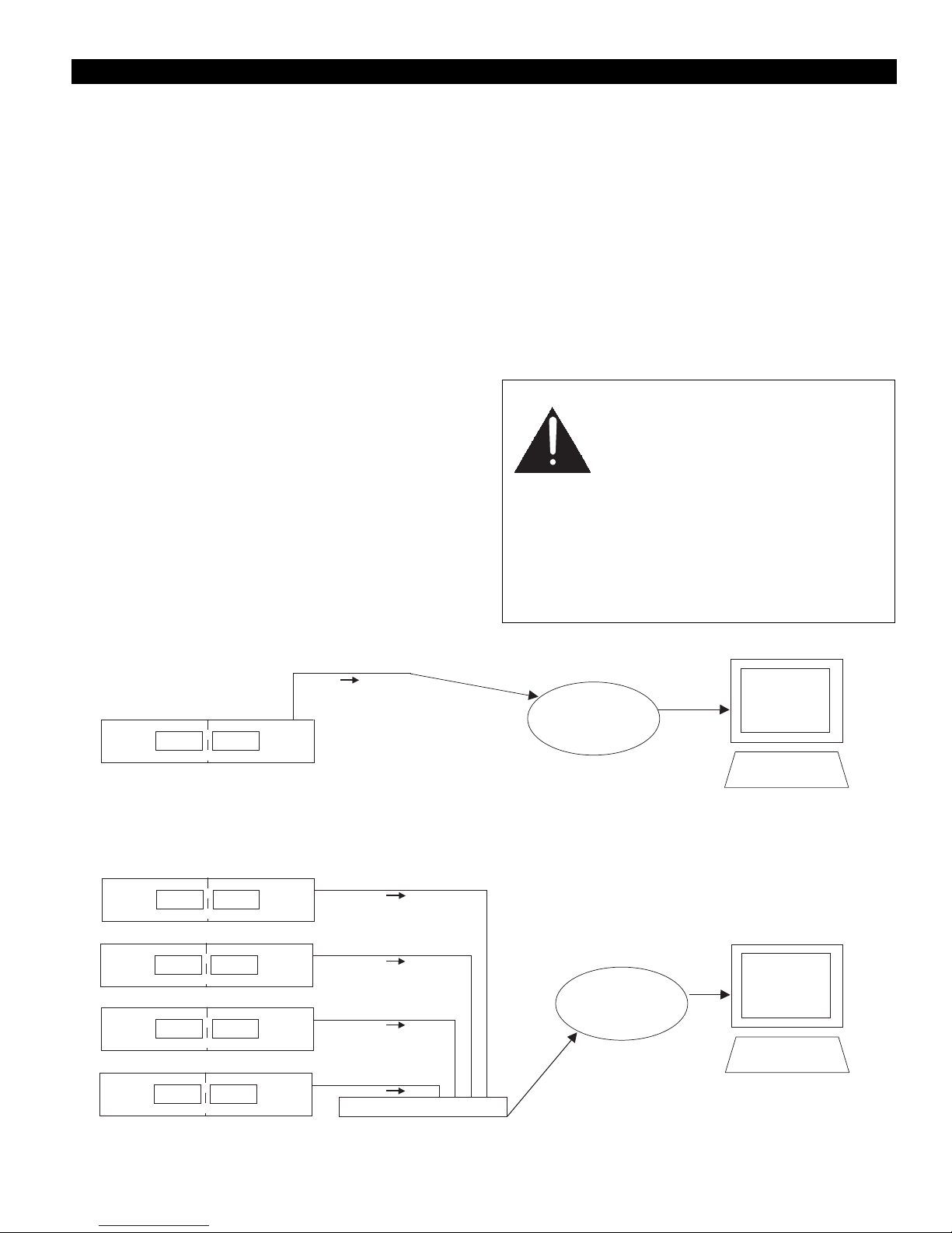
To connect one or more AEW-R5200 receivers to an existing network to which your
computer is also connected ..........................................................................................................................................6
To connect one or more AEW-R5200 receivers using DHCP-supporting router ............................................................6
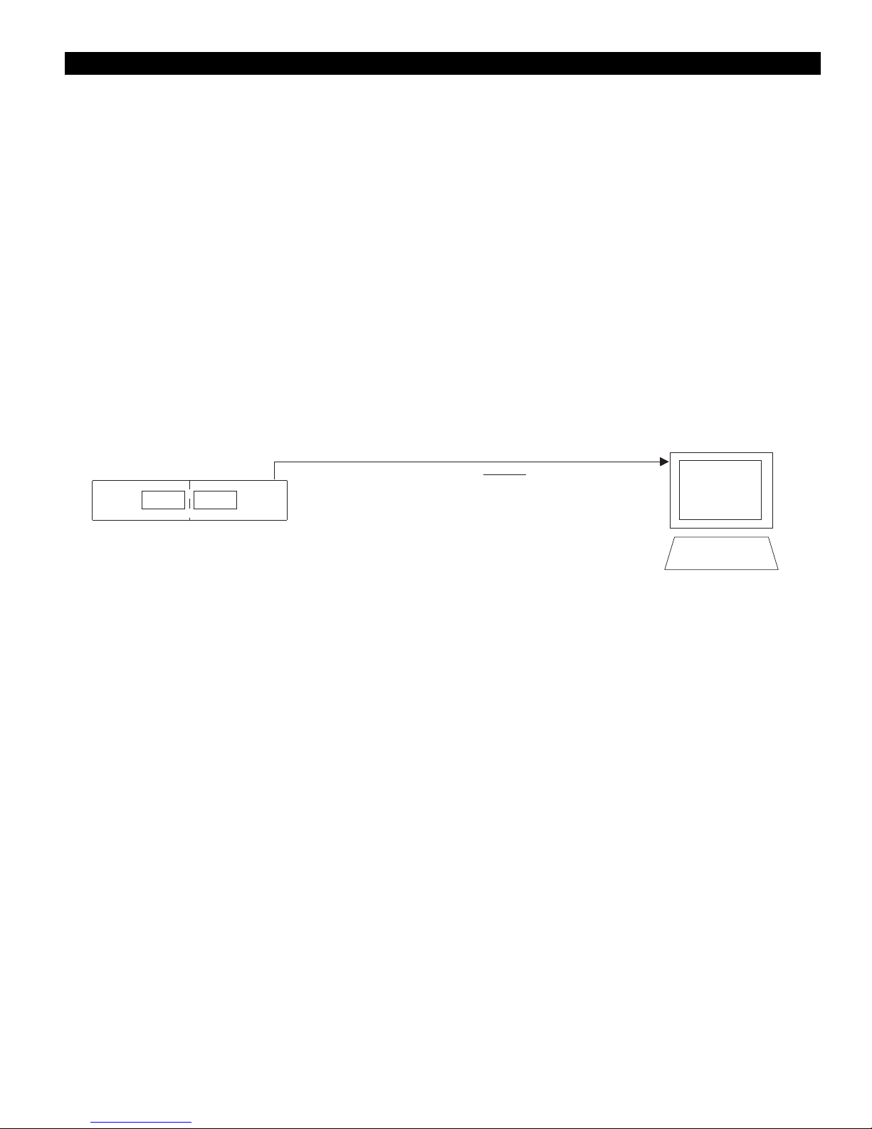
To connect a single AEW-R5200 directly to a computer's Ethernet card ......................................................................7
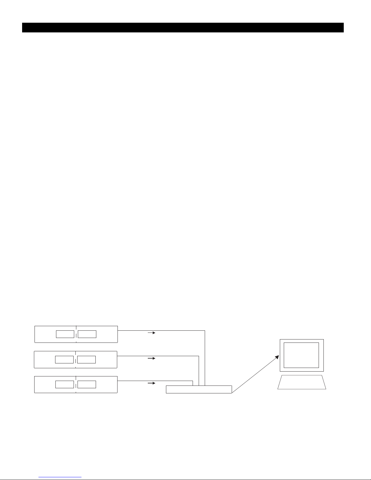
To connect multiple receivers via link cables (for systems that include AEW-R4100
receivers, or for systems without access to multiple Ethernet connections) ..............................................................8
To link receivers via link cables........................................................................................................................................8
To set up remote access to the AEW-R5200 via the Internet ........................................................................................9
Installing and Using the Software ..........................................................................................................................................9
Installing the software (PC) and (Macintosh) ........................................................................................................................9
Getting started ......................................................................................................................................................................9
Navigating the Software ......................................................................................................................................................10
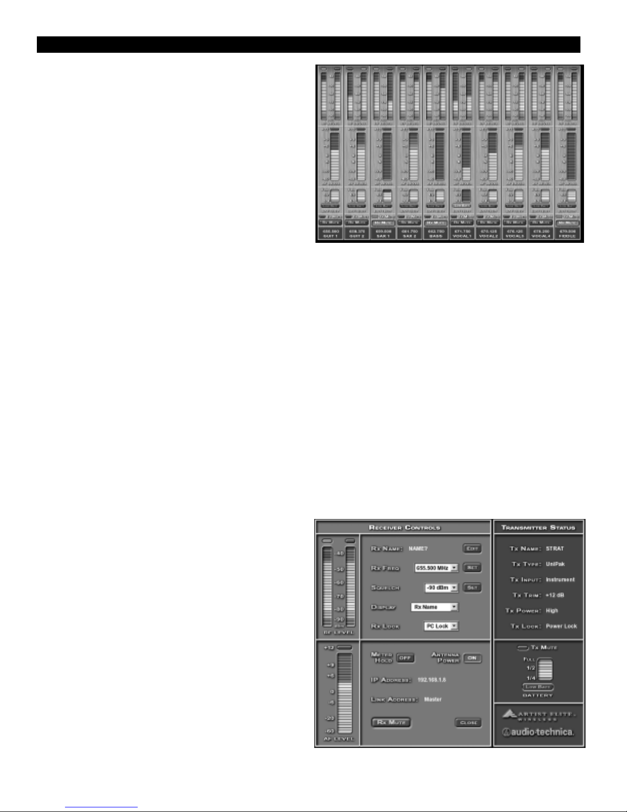
Main System Window ..................................................................................................................................................10
Channel Detail Window ................................................................................................................................................10
Changing Receiver Name ..............................................................................................................................................11
Changing Frequency ......................................................................................................................................................11
Changing Squelch ..........................................................................................................................................................11
Changing Display Name ................................................................................................................................................11
Changing Lock Setting ..................................................................................................................................................11
Changing Meter Hold Setting ........................................................................................................................................11
Changing Antenna Power Setting..................................................................................................................................11
Muting/Unmuting System..............................................................................................................................................11
Mute ALL ......................................................................................................................................................................11
Navigating the File Menu ....................................................................................................................................................12
Open Environment ........................................................................................................................................................12
Save Environment..........................................................................................................................................................12
Receiver Configuration ..................................................................................................................................................12
To change the order of display of a receiver ..........................................................................................................12
To enable or disable a receiver................................................................................................................................12
Network Configuration ..................................................................................................................................................12
To add a remote receiver by entering its IP address ..............................................................................................12
Exit ................................................................................................................................................................................12
Navigating the Tools Menu ..................................................................................................................................................13
IntelliScan™....................................................................................................................................................................13
Spectrum Analyzer ........................................................................................................................................................14
Coverage Test ................................................................................................................................................................14
Reconnect to Network ..................................................................................................................................................14
Navigating the View Menu ..................................................................................................................................................15
Channel Display ............................................................................................................................................................15
Name Display ................................................................................................................................................................15
Navigating the Help Menu ..................................................................................................................................................15
Contents ........................................................................................................................................................................15
About ............................................................................................................................................................................15
Installing and Using the AE Reflector Serivce ....................................................................................................................15
General ..........................................................................................................................................................................15
Installing AE Reflector ..................................................................................................................................................15
2