Audio Technica ATDM-0604A User manual

ATDM-0604a
User Manual
DIGITAL SMARTMIXER

2
Introduction
Thank you for purchasing this Audio-Technica product.
Before using the product, read through this user manual to ensure that you will use the product correctly. Please keep this manual for future
reference.
Checking the package contents
Before use, check to make sure that all of the following items are contained in the package.
If any of the items is missing from your package or damaged, contact your local Audio-Technica dealer.
• ATDM-0604a unit
• Euroblock connector ×11
• Rack-mount (large, small)
• Rack-mount screw ×6
• Power cable
• Rubber feet ×4
• Quick Start Guide
Trademarks
• SMARTMIXERTM is a trademark or registered trademark of Audio-Technica Corporation.
• Apple and the Apple logo are trademarks of Apple Inc., registered in the U.S. and other countries.
• iOS is a trademark or registered trademark of Cisco in the U.S. and other countries.
• App Store is a service mark of Apple Inc.
• Google, the Google logo, Google Play, the Google Play logo, and AndroidTM are trademarks or registered trademarks of Google Inc.
• All other company and product names that appear in this document are trademarks or registered trademarks of their respective owners.

3
Safety precautions
Important information
Warning:
To prevent fire or shock hazard, do not expose this apparatus to rain or moisture.
Caution:
• Do not expose this apparatus to drips or splashes.
• To avoid electric shock, do not open the cabinet.
• Refer servicing to qualified personnel only.
• Do not expose this apparatus to excessive heat such as sunshine, fire or the like.
• Do not subject this apparatus to strong impact.
• This apparatus should be located close enough to the AC outlet so that you can easily grasp the power cord plug at any time.
• In case of emergency, disconnect the power cord plug of this apparatus quickly.
• Do not place any objects filled with liquids, such as vases, on this apparatus.
• To prevent fire, do not place any naked flame sources (such as lighted candles) on this apparatus.
• Do not install this apparatus in a confined space such as a bookcase or similar unit.
• Install this apparatus only in the place where ventilation is good.
• This apparatus is not disconnected from the mains as long as it is connected to the AC outlet, even if the unit itself has been turned off.
• Keep the product out of the reach of small children. The product is not intended for use around children.
• Do not place the product near fire to avoid an accident or the product catching fire.
For customers in the USA/Canada
Important safety instructions
1) Read these instructions.
2) Keep these instructions.
3) Heed all warnings.
4) Follow all instructions.
5) Do not use this apparatus near water.
6) Clean only with dry cloth.
7) Do not block any of the ventilation openings. Install in accordance with the manufacturer’s instructions.
8) Do not install near any heat sources such as radiators, heat registers, stoves, or other apparatus (including amplifiers) that produce heat.
9) Do not defeat the safety purpose of the polarized or grounding plug. A polarized plug has two blades with one wider than the other. A
grounding plug has two blades and a third grounding prong. The wide blade or the third prong is provided for your safety. If the provided
plug does not fit into your outlet, consult an electrician for replacement of the obsolete outlet.
10) Protect the power cord from being walked on or pinched particularly at plugs, convenience receptacles, and the point where they exit from
the apparatus.
11) Only use attachments/accessories specified by the manufacturer.
12) Use only with a cart, stand, tripod, bracket, or table specified by the manufacturer, or sold with the apparatus.
13) When a cart is used, use caution when moving the cart/apparatus combination to avoid injury from tip-over.
14) Unplug this apparatus during lightning storms or when unused for long periods of time.
15) Refer all servicing to qualified service personnel. Servicing is required when the apparatus has been damaged in any way, such as power-
supply cord or plug is damaged, liquid has been spilled or objects have fallen into the apparatus, the apparatus has been exposed to rain or
moisture, does not operate normally, or has been dropped.
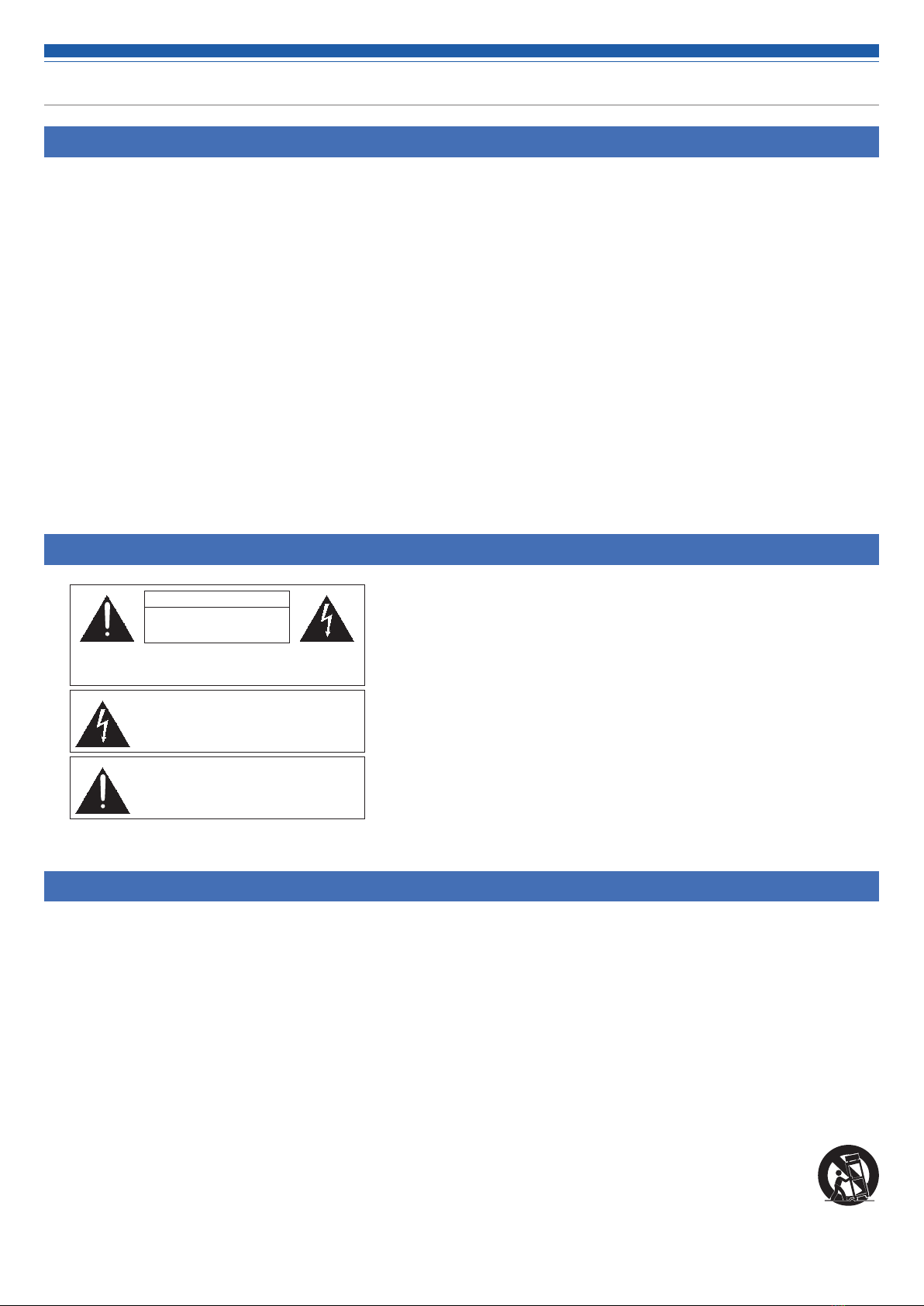
CAUTION
RISK OF ELECTRIC SHOCK
DO NOT OPEN
Caution: To prevent electric shock, do not remove the cover. There
are no user-serviceable parts inside. Internal adjustments are for
qualified professionals only. Refer all servicing to qualified service
personnel.
The lightning flash with arrowhead symbol, within an
equilateral triangle, is intended to alert the user to the
presence of uninsulated “dangerous voltage” within
the product’s enclosure that may be of sufficient
magnitude to constitute a risk of shock to persons.
The exclamation point symbol within an equilateral
triangle is intended to alert the user to the presence
of important operating and maintenance (servicing)
instructions in the literature accompanying the
product.
12)

4
Safety precautions
FCC notice
Warning:
This device complies with Part 15 of the FCC Rules. Operation is subject to the following two conditions: (1) This device may not cause harmful
interference, and (2) this device must accept any interference received, including interference that may cause undesired operation.
Caution:
You are cautioned that any changes or modifications not expressly approved in this manual could void your authority to operate this equipment.
Note:
–This equipment has been tested and found to comply with the limits for a Class B digital device, pursuant to part 15 of the FCC Rules. These
limits are designed to provide reasonable protection against harmful interference in a residential installation. This equipment generates, uses and
can radiate radio frequency energy and, if not installed and used in accordance with the instructions, may cause harmful interference to radio
communications. However, there is no guarantee that interference will not occur in a particular installation. If this equipment does cause harmful
interference to radio or television reception, which can be determined by turning the equipment off and on, the user is encouraged to try to
correct the interference by one or more of the following measures:
–Reorient or relocate the receiving antenna.
–Increase the separation between the equipment and receiver.
–Connect the equipment into an outlet on a circuit different from that to which the receiver is connected.
–Consult the dealer or an experienced radio/TV technician for help.
Contact:
Responsible Company: Audio-Technica U.S., Inc. Address: 1221 Commerce Drive, Stow, Ohio 44224, USA Tel: 330-686-2600
For customers in Canada
ISED statement
CAN ICES-003(B)/NMB-003(B)

5
Notes on use
• When using the product, also read the user manuals supplied with the devices that are to be connected.
• When not using the product, remove the power plug from the power outlet.
• Turn the product off before connecting or disconnecting cables.
• If you use the product near a TV or radio antenna, noise may be generated in the TV or radio. In this case, move the product away from the TV
or radio antenna.
Maintenance
• If the product becomes dirty or dusty, disconnect the power plug first, and then wipe the product off with a dry soft cloth.
• Do not use benzine, thinner, contact restoring protective agent, or any other chemical agent. Doing so may cause deformation, damage, or
malfunction.
• When storing the product for an extended period of time, wrap it with a plastic cover, and do not allow it to be exposed to humidity.

6
Features
Features of ATDM-0604a
• 6 mic/line inputs and 1 unbalanced stereo input, implementing high-quality mic preamplifier with discrete amplifier
• Flip function allows switching between balanced and unbalanced outputs in stereo units. 1 unbalanced output can be output at microphone level
• USB audio I/O (1 stereo input and 1 stereo output)
• Built-in SmartMixer that allows for a selection between gain sharing and gate modes
• 6 microphone inputs with AEC for simultaneous use
• Simultaneous use with noise canceller (1 unit) possible
• 4-band EQ, comp/de-esser on each input, 12-band EQ on each output
• Comp and limiter on each input and output system. Pre/Post Fader selectable for each output
• 8-band feedback suppressors can be inserted into inputs and outputs (up to 8 units)
• Audio input/output settings can be configured on the front panel, whereas the advanced settings can be configured on a computer using Web
Remote.
• Allows for external control with IP Remote Protocol
• Up to one ES954 hanging array microphone (sold separately) can be connected to the microphone input
• Supports external muting of the ES954 hanging microphone from the mixer and can be set from a PC using the web remote
• Equipped with a ducking function
About Audio-Technica LINK
This product can daisy-chain up to eight ATDM-0604a units to support 48 mic/line inputs and 8 unbalanced stereo audio inputs for the entire
system. The proprietary Audio-Technica LINK functionality enables the transmission of low-latency, high-speed audio bus signals between devices,
making it possible to steadily control and transmit uncompressed audio signals.
Furthermore, the model offers excellent workability as it conforms to the Ethernet standards and can be connected to generic LAN cables (shielded
cables of Cat5e or above with the conductor diameter size of 24 AWG or larger must be used).
System installation
Installing on a rack
The product can be installed using the supplied rack-mount.
• When installing this product in a rack, ensure that the temperature inside the rack does not exceed 40°C. This will adversely affect the internal
components and cause malfunctions.
• Ensure at least a 10-centimeter space between the product and other devices or the top, side, and back faces of the rack.
• The required rack specifications are as follows.
– EIA-standard 19-inch rack
– 1U-size attachable rack
– Rack with a shelf on which the product is placed or a guide rail that supports the product
• The rack mounts are affixed to the product with the following screws. Check the following when using screws other than those supplied.
– S-tight (tapping screw), nominal diameter 4 × 6 mm

7
System installation
Rack-mount screw x 6
(supplied with the product)
Rack mount (small)
(supplied with the product)
Rack mount (large)
(supplied with the product)
1. Attach the rack mounts to the product.
2. Install the product on the rack.
• To install the product on the rack, use the screws supplied with the rack
or commercially available screws.

8
System installation
Unbalanced connection
An unbalanced connection tends to be subject to induction noise caused by the chassis potential differences. Be sure to match the chassis
potentials between devices.
• Match the power supply phases between devices.
• Standardize the power supply systems.
• Connect the GND (ground) terminal or chassis of each device.
Power cable connection
• Connect the power plug to the appropriate outlet with protective grounding. Electric shock may result if the plug is not grounded securely.
How to connect a Euroblock connector
1. As shown in the figure, expose the wires inside the cable.
• Do not solder the stranded wires.
2. Loosen the screws with a flathead screwdriver.
3. Verify the pin assignments, and connect each to the applicable
wire.
• Pin assignments
123
INPUT
1 to 6 +: HOT -: COLD G: GND
ST R: RIGHT L: LEFT G: GND
OUTPUT
1/L, 2/R +: HOT -: COLD G: GND
UNBAL R: RIGHT L: LEFT G: GND
4. Tighten the screws and bundle the wires with a cable tie.
5. Connect the Euroblock connector to the product.
1 2 3
Approx. 5 mm
Approx. 20 mm
Use any commercially
available cable tie.

9
System connection examples
Local discussion (Preset #2)
Web Remote
for operator
Near-end source
Balanced audio cable
Ceiling speaker
Main speaker
Power amplifier
Power amplifier
AC power
AC power cableEthernet cable
Switching hub
Router
AP
Tablet / Smartphone
Mic

10
System connection examples
Remote discussion - web conference (Preset #3)
Remote discussion - video conference (Preset #4)
Tablet / Smartphone
Web Remote
for operator
Near-end source
Balanced audio cable
Powered speaker
AC power
Unbalanced audio cable
AC power cableUSB cableLAN cable
Switching hubRouter
AP
Internet
Far-end source
Computer
Mic
Video
conferencing
system
Web Remote
for operator
Near-end source
Unbalanced audio cable
Balanced audio cable
Unbalanced audio cable
Balanced audio cable
Ceiling speaker
Power amplifier
AC power
AC power cableEthernet cable
Switching hubRouter
AP
Tablet / Smartphone
Mic
Far-end source
Far-end source
Internet

11
Part names and function
Front Panel
❿ SIG/PK·ASSIGN LED
Indicates the signal level of input channel 6 when the level or gain
is being adjusted.
Also lights when on/off of the output bus assignment is set.
⓫ SIG/PK·AEC LED
Indicates the signal level of input channel ST when the level or
gain is being adjusted.
Also lights when on/off of the AEC is set.
⓬ SIG/PK·PRESET SAVE LED
Indicates the signal level of an output channel when the level or
gain is being adjusted.
Also lights when a preset is saved.
⓭ OUTPUT SEL LED
Indicates if an output channel is selected.
⓮ MODE button
Selects a function.
⓯ INPUT SEL button
Selects an input channel or preset number.
⓰ OUTPUT SEL button
Selects the output channel. Lights green for Output 1, red for
Output 2, or yellow for Output ST.
⓱ Volume LED
Indicates the current setting of the selected channel when the
level or gain is being adjusted.
⓲ Dial button
Turn the dial button to select, and push to confirm the selection.
❶ Power button
Turns on/off the power to the product.
❷ PRESET LED
Lights and blinks when the power is turned on and indicates that
the product is being started.
Lights when a preset is being recalled.
❸ LEVEL·GAIN LED
Lit: You can adjust the input level and output level.
Blinking: You can adjust the gain.
❹ INPUT SEL LED
Indicates the input channel, preset bank number, and the status of
the function/setting of each channel.
❺ SIG/PK·MIC/LINE LED
Indicates the signal level of input channel 1 when the level or gain
is being adjusted.
Also lights when the input type is changed (MIC/LINE).
❻ SIG/PK·PHANTOM LED
Indicates the signal level of input channel 2 when the level or gain
is being adjusted.
Also lights when on/off of the phantom power is set.
❼ SIG/PK·LOW CUT LED
Indicates the signal level of input channel 3 when the level or gain
is being adjusted.
Also lights when on/off of the low-cut is set.
❽ SIG/PK·PRIORITY LED
Indicates the signal level of input channel 4 when the level or gain
is being adjusted.
Also lights when on/off of the priority is set.
❾ SIG/PK·SMART MIX LED
Indicates the signal level of input channel 5 when the level or gain
is being adjusted.
Also lights when on/off of the SmartMixer is set.
❸❺ ❸ ❹ ❺ ❻ ❼ ❽ ❾ ❿ ⓫ ⓭⓬
⓮ ⓯ ⓰ ⓲⓱

12
Part names and function
• An LED can be in one of five statuses.
(1) Lit: Indicates that a function is selected and enabled, etc.
(2) Off: Indicates that a function is not selected and disabled, etc.
(3) Blinking: Indicates that a function is being selected. Repeats every 500 ms until the status changes.
(4) Blinking fast: Indicates that the operation has been rejected. Repeats blinking five times every 200 ms.
(5) Dimmer lit: Indicates lower brightness.
• The signal level ranges indicated by the SIG/PK LEDs are as follows.
- LED lit (red): 0 dBFS to -5 dBFS
- LED lit (yellow): -6 dBFS to -24 dBFS
- LED lit (green): - 25 dBFS to - 59 dBFS
- LED off: -60 dBFS or less
Rear panel
❻ NETWORKterminal
A NETWORK port. Connect an Ethernet cable (Cat5e or above).
❼ GPOterminals
General-purpose output pin. Pin assignments are 1: GPO1, 2:
GPO2, G: GND.
❽ USBterminal
A USB port (USB Type B). Connect a USB cable.
❾ LINKA/Bterminals
A LINK A/B port. Used for Audio-Technica LINK.
Connect LAN cable (CAT5e or higher, conductor size 24AWG
diameter or larger, shielded must be used).
❿ ACInlet
Connect the power cable.
❶ Unbalanced input terminal (ST)
An unbalanced input port. Connect an unbalanced cable.
Pin assignments are as follows. 1: STEREO R 2: STEREO L and 3:
GND.
❷ Balanced input terminals (MIC/LINE)
A balanced input port. Connect a balanced cable. The input type
setting (MIC/LINE) can be changed.
Pin assignments are as follows. 1: HOT, 2: COLD, and 3: GND.
❸ Unbalanced output terminal (UNBAL)
An unbalanced output port. Connect an unbalanced cable.
Pin assignments are as follows. 1: STEREO R/2 2: STEREO L/1 and
3: GND.
❹ Balanced output terminals (BAL 1/L and 2/R)
A balanced output port. Connect a balanced cable.
Pin assignments are as follows. 1: HOT, 2: COLD, and 3: GND.
❺ Screwsforgrounding
The supplied power cable is a 2-core cable, and cannot be used
for grounding. Ground the product as necessary.
❸ ❺ ❷
❹
❶ ❻
❽ ❾ ❿❼

13
Using the product
Starting the product
1. Press the power button.
• The PRESET LED lights, blinks, and LEVEL·GAIN LED turns on. Then, the
PRESET LED turns off, and the product starts in operator mode.
2. The volume LED lights according to the IP Config Mode setting.
Front panel mode
The following two modes are available when operating the product
with the buttons and the dial on the front panel.
Operator mode:
In this mode, daily operations are performed, such as loading the preset settings
and adjusting the audio level.
Advanced mode:
In this mode, advanced settings can be configured by installing and implementing
the product on-site.
• When the power is turned on, the product usually starts in operator
mode. This prevents accidental device setting changes or other troubles,
and ensures a safe operation of the system.
Switch front panel mode
(operator mode/advancedmode/advanced mode)
Change between operator mode and advanced mode.
1. While pressing the MODE button, press and hold the dial button
(for 1 or more seconds).
2. LEDs light/blink/turn off, and the front panel mode changes.
• When changing to operator mode
(1) The LEVEL·GAIN LED and the PRESET LED light.
(2) The PRESET LED turns off.
(3) The front panel mode changes to operator mode.
• When changing to advanced mode
(1) The LEVEL·GAIN LED, the PRESET LED, and the LEDs from SIG/PK·MIC/
LINE to SIG/PK·PRESET SAVE become lit.
(2) All LEDs turn off except the LEVEL·GAIN LED, which blinks.
(3) The front panel mode changes to advanced mode.
Selecting a function
Press the MODE button, or turn the dial button while pressing the
MODE button, to select the function.
• Determine the function selected based on the LED that lights (LEVEL·GAIN
LED and PRESET LED, or an LED from SIG/PK·MIC/LINE to SIG/PK·PRESET
SAVE).
Functions available in operator mode
Functions available in advanced mode
Press the MODE button to change the function in the clockwise
direction as shown in the figure. While pressing the MODE button, turn
the dial button to change the function to the one in the direction of the
dial.
LEVEL
Start of function selection
PRESET
GAIN
PRESET
PRESET SAVE
AEC
ASSIGN
SMART MIX PRIORITY
LOW CUT
PHANTOM
MIC/LINE
LEVEL
Start of function selection
Auto Static

14
Using the product
Operations that can be performed in
operator mode/advanced mode
Recalling a preset
Recall saved preset data to change the current setting.
1. Select “PRESET”.
• The PRESET LED lights.
2. Push the INPUT SEL button to select the preset data to recall
(from 1 to 6).
• The INPUT SEL LED and the volume LED light.
3. Press the dial button.
• The preset data is read and the settings change.
Adjusting the input level
Set the input level to MIC or LINE. If “LINE” input type is selected, PAD
(a function to attenuate the input signal by a certain level) is entered.
1. Select "LEVEL."
• The LEVEL·GAIN LED lights.
• The SIG/PK LED of each input channel becomes lit based on the input
level.
2. Press the INPUT SEL button to select the input channel you
want to adjust.
• The INPUT SEL LED lights, and the volume LED lights according to the
setting.
• The volume LED that indicates the 0 dB (-20 dBFS) point blinks.
3. Turn the dial button to adjust the input level.
• The volume LED becomes lit/turns off based on the adjusting operation.
• When the level is at the 0 dB (-20 dBFS) point, the blinking volume LED
becomes lit.
Adjusting the output level
Set the output level.
1. Select "LEVEL."
• The LEVEL·GAIN LED lights.
• The SIG/PK LED of the output channel becomes lit based on the output
level.
2. Push the OUTPUT SEL button to select the output channel you
want to adjust.
• The color of the OUTPUT SEL LED changes, and it lights according to the
selected output channel (OUTPUT 1: Green, OUTPUT 2: Red, OUTPUT ST:
Yellow). The volume LED lights according to the setting.
• The volume LED that indicates the 0 dB (-20 dBFS) point blinks.
3. Turn the dial button to adjust the output level.
• The volume LED becomes lit/turns off based on the adjusting operation.
• When the level is at the 0 dB (-20 dBFS) point, the blinking volume LED
becomes lit.
Operations available only in advanced mode
Change to advanced mode to perform these operations.
Changing the input type (MIC/LINE)
Specify the input type. Only input channel 5 and input channel 6 can
be set.
1. Select "MIC/LINE."
• The SIG/PK·MIC/LINE LED lights.
2. Press the INPUT SEL button to change the input type between
MIC and LINE (+4dBu).
• The INPUT SEL LED lights when LINE is selected, and it turns off when
MIC is selected.
• Input channels 1 to 4 switch to LINE (-10 dBV), and input channels 5 and
6 switch to LINE (+4 dBV).
Adjusting the gain
Set the input gain for MIC input.
1. Select "GAIN."
• The LEVEL·GAIN LED blinks.
• The SIG/PK LED of each input channel becomes lit based on the input
level.
2. Press the INPUT SEL button to select the input channel you
want to adjust.
• The INPUT SEL LED lights, and the volume LED lights according to the
setting.
• The volume LED that indicates the -40 dB point blinks (only when ”MIC”
is selected as the input type).
3. Turn the dial button to adjust the gain.
• The volume LED becomes lit/turns off based on the adjusting operation.
• When the level is at the -40 dB point, the blinking volume LED becomes
lit.
• During gain adjustment, press the dial button to switch the
volume LED display between gain setting value and level
meter. Change the display as necessary. Also, the unity level
of each audio output can be switched using the OUTPUT SEL
button and dial button.
Turning the phantom power ON/OFF
Turn on/off the phantom power (+48V). This setting can be made only
when the input type is set to “MIC”.
1. Select "PHANTOM."
• The SIG/PK·PHANTOM LED lights.
2. Press the INPUT SEL button to switch the phantom power
between ON and OFF.
• The INPUT SEL LED lights when the phantom power is turned on, and it
turns off when the phantom power is turned off.
Saving a preset
Save the current settings as a preset.
1. Select "PRESET SAVE".
• The SIG/PK·PRESET SAVE LED lights.
• If a preset is currently recalled, the INPUT SEL LED of that preset number
becomes lit.
2. Press the INPUT SEL button to select the saving location (from
PRESET 1 to PRESET 6).
• The INPUT SEL LED and the volume LED blink.
3. Press the dial button.
• The preset is saved to the specified saving location.

15
Using the product
Turning the low-cut ON/OFF
Specify whether or not to remove low frequencies from the audio
signal.
1. Select "LOW CUT".
• The SIG/PK·LOW CUT LED lights.
2. Press the INPUT SEL button to switch the low-cut between ON
and OFF.
• The INPUT SEL LED lights when the low-cut setting is turned on, and it
turns off when the low-cut setting is turned off.
Turning the priority ON/OFF
Set the channel priority. The priority can be set only when SmartMixer
is turned on, and gate mode is selected.
1. Select "PRIORITY".
• The SIG/PK·PRIORITY LED lights.
2. Press the INPUT SEL button to switch the priority between ON
and OFF.
• The INPUT SEL LED lights when the priority is turned on. The INPUT SEL
LED turns off when the priority is turned off.
Turning SmartMixer enable/disable
Switch SmartMixer between enable/disable.
Set SmartMixer mode (gate mode or gain sharing mode) via Web
Remote (p.53).
1. Select "SMART MIX".
• The SIG/PK·SMART MIX LED lights.
2. Press the INPUT SEL button to switch the SmartMixer between
enable/disable.
• INPUT SEL LED lit:
The Smart Mixer is enabled and its channels mix audio in gated or gain-
share mode.
• INPUT SEL LED off:
Smart Mixer is invalid.
Setting the bus assignment
Assign and confirm the output bus for an input channel.
1. Select "ASSIGN".
• The SIG/PK·AEC LED lights.
2. Press the OUTPUT SEL button to select the output bus to be
assigned and confirmed.
• If the INPUT SEL LED is lit, the channel is assigned to the selected output
bus. If the light is off, it is not assigned.
• Press the INPUT SEL button to switch the bus assignment.
INPUT SEL LED lit:
Assigned to the output bus. Even when the Smart Mixer is on, the audio
signal is output through the Smart Mixer.
INPUT SEL LED blinking:
Assigned to the output bus. Audio signals processed by SmartMixer are
output when SmartMixer is turned ON.
INPUT SEL LED off:
Not assigned to any output bus.
Turning the AEC ON/OFF
Turn on/off the AEC (Acoustic Echo Canceler).
1. Select "AEC".
• The SIG/PK·AEC LED lights.
2. Press the INPUT SEL button to switch the AEC between ON and
OFF.
• The INPUT SEL LED lights when the AEC is turned on, and it turns off
when the AEC is turned off.
• Press the INPUT SEL button for the input channel ST to switch the AEC
mode.
INPUT SEL LED of input channel ST lights up. AEC with NC
INPUT SEL LED of input channel ST blinks. Noise Canceling
INPUT SEL LED of input channel ST goes off. OFF
Changing the IP config mode (Auto/Static)
Specify how to obtain the IP address.
1. Press the power button.
• The PRESET LED becomes lit.
2. When the PRESET LED starts blinking, press down the MODE
button, the INPUT SEL button for INPUT channel 4 and the
OUTPUT SEL button.
3. When the LEVEL LED becomes lit, release the MODE button,
the INPUT SEL button for INPUT channel 4, and the OUTPUT
SEL button.
4. The volume LED lights according to the IP Config Mode setting.
5. Turn the dial button and change the IP Config Mode.
6. Restart the product.
Auto Static

16
Using the product
Locking the front panel
A lock can be applied so that the front panel operation is disabled.
1. While pressing the OUTPUT SEL button, press and hold the dial
button (for 1 or more seconds).
• The front panel becomes locked. Repeat the same steps to disable the
lock and enable input/output level adjustment in operator mode or gain
adjustment in advanced mode.
• The PRESET LED, the LEVEL/GAIN LED, the INPUT SEL LED, and the
volume LED turn off.
• The OUTPUT SEL LED is on while the panel is locked.
• Other LEDs turn on based on the level of an audio input.
Checking the firmware version
You can view the firmware version of the product.
1. Press the power button.
• The PRESET LED becomes lit.
2. When the PRESET LED starts blinking, press and hold the
MODE button and the dial button.
3. When the LEVEL LED becomes lit, release the buttons.
• LEDs light according to the firmware version.
(Example) When the firmware version is “02.03.05”
4. Check the firmware version, and turn off the product.
Indicates “02”
Represents "03".
Inficates "05".

17
Web Remote
What Is Web Remote?
Web Remote is a web-based application for controlling this product.
The following items can be remotely controlled from Windows PCs,
Macs, iOS devices, and Android devices (hereinafter referred to as
"control devices").
• Check the status of the product
• Change the various settings of the product
What is “Locate”?
"Locate" is a launcher application for Web Remote. Connect your
control device, then activate "Locate". With "Locate", you can quickly
access Web Remote without entering the IP address assigned to the
product.
• You can also launch Web Remote without using "Locate".
Recommended environment
OS supporting Web Remote and "Locate"
• Microsoft Windows 10 or later
• macOS Big Sur or later
• Android OS 5.0 or later
• iOS 9 or later
Recommended web browsers for Web Remote
• Microsoft Edge 96 or later (Windows)
• Google Chrome ver. 57 or later (Windows and Android)
• Safari 10 or later (OS X and iOS)
• You can log into Web Remote from up to 3 control devices at the same
time. If two different web browsers are running on one control device,
Web Remote recognizes access from two control devices.
• To exit Web Remote, make sure to log out first, and then close the web
browser screen. If the screen is closed without logging out, the session
may continue, and you may remain logged into Web Remote.
• The minimum size of the web remote screen is 1024 x 768 pixels. For the
control device, use a large enough display monitor to display the Web
Remote screen in the web browser.
Preparing Web Remote
Connect a control device to the product
1. Before connecting a control device to the product, network
settings for both devices must be performed.
• If IP addresses are obtained automatically when connecting
(1) Set the product’s IP Config Mode to “Auto”.
– The product ships from the factory in “Auto” mode.
(2) Set the control device’s network settings so that it connects to the
network.
• If static IP addresses are used when connecting
(1) Set the product’s IP Config Mode to “Static”.
– The IP address is set to a static value.
The default value is “192.168.33.102”.
2. Use a wired or wireless connection to connect the control
device to the product.
3. Turn on the control device and the product.
• If IP addresses are obtained automatically when connecting, it may take
some time before the IP address is set.
Setting up "Locate"
1. Download the "Locate" installer/application to the control
device.
• For Windows and Mac:
Download from the Audio-Technica website (www.audio-technica.com)
for your country or region.
• For iOS and Android:
Download from the App Store or Google Play.
Upon completion of the download, proceed to Step 4.
2. Double-click “setup.exe” you have downloaded.
• The Setup Wizard opens.
3. Follow the on-screen instructions to install "Locate".
• When installation is complete, the "Locate" icon appears on the desktop.
4. Make sure ATDM-0604a is connected to the same network as
the control device and powered on, then double-click on the
"Locate " icon.
• "Locate" launches. The ATDM-0604a connected to the network is
automatically detected.
5. Select the ATDM-0604a for which you want to perform Web
remote control and click "Open".
• The Web Remote Login screen appears.
• When the "Identify" icon is clicked, the icon will flash red and the
indicators on the front panel of the corresponding ATDM-0604a will flash.
Use this if you have more than one ATDM-0604a on your system and
want to identify the ATDM-0604a that appears in the "Locate " list.

18
Web Remote
Overview of Web Remote
Log in as the Administrator
Log in as the Operator
Windows/Mac display iOS/Android screen
Audio Settings
Input: Set the various options, such as Gain, Level, EQ, and SmartMixer, for audio
input from a microphone or other audio devices.
Output: Set the various options, such as Level, FBS, EQ, and Dynamics, for audio
output.
Settings & Maintenance
System Settings:
Set the options relating to Network, Access Permissions, Audio-Technica LINK,
etc., and update the firmware.d
Operator Access:
Set the various options relating to the operation screens you can access after
logging in as the Operator.
Presets: Recall and save presets and import/export preset data to/from external devices.
Logging: Set the options relating to log messages, and download log messages.
System Info: System information, such as the various network settings and the product’s
serial number and firmware version, is displayed.
Login screen
• To log in as the administrator, you must use a Windows PC or a Mac computer. Operations using a tablet or a smartphone are not guaranteed.

19
Launch/Log into Web Remote
Launching Web Remote
Start from " Locate
1. Launch "Locate" you have installed in the control device.
2. Select the ATDM-0604a you wish to activate the web remote
from the list.
• Web Remote launches, and the Login screen appears.
Specifying an IP address to launch the Web Remote
If you know the IP address of the product, you can launch Web Remote
by specifying the IP address directly.
1. Open the control device’s web browser.
2. Enter the IP address of the ATDM-0604a from which you want
to activate the web remote.
• Web Remote launches, and the Login screen appears.
Login screen
❶Device name
The name set for the product is displayed.
❷Mode selection
Select “Operator” or “Administrator” as the login user.
❸Password
Enter the password.
• This field appears when login as the Administrator is locked. For
the password settings, refer to p.43.
❹Login button
❺Language
Select the display language for Web Remote.
Logging into Web Remote
1. Select “Operator” or “Administrator”, and then click “Login”.
• If “Administrator” is selected, the password entry field appears. Enter the
password, and then click “Login”.
Logging out of Web Remote
1. Click the Logout icon.
2. Click “Logout”.
• Log out of Web Remote.
❶
❷
❸
❹
❺

20
Operator screen
If you log in as the Operator, you can import the presets, adjust the volumes, and set other options required in day-to-day operations, through simple
steps.
Windows/Mac display iOS/Android screen
❶ Array microphone ON/OFF
Each click toggles the array microphone on and off.
❷ Preset display
Click to recall a desired preset.
❸ Volume adjustment dial
Adjust the volume of each input/output channel.
Blue: Input channel
Red: Output channel
❹ Input/Output icon
Icons and display names are displayed according to the contents
of "Fader Settings" (p.46). Mute turns ON/OFF each time the icon
is clicked.
❺Level meter
The level of each channel is displayed.
• Input channel:
Blue: Input received
Gray: No input
• Output channel:
Blue: Level between -6 to -59 dBFS
Red: Level equal to or greater than -5 dBFS
Gray: No input
❻Reference point
The balance is set as adjusted on the Audio Input Screen at the
reference point (70%).
❶
❸
❹
❺
❻
❶
❹
❸
❻
❺
❷
❷
Other manuals for ATDM-0604A
1
Table of contents
Other Audio Technica Recording Equipment manuals

Audio Technica
Audio Technica ATN3600L User manual

Audio Technica
Audio Technica ATW-0814 User manual

Audio Technica
Audio Technica System 10 Stompbox ATW-1501 Owner's manual

Audio Technica
Audio Technica ARTIST ELITE 5000 Owner's manual

Audio Technica
Audio Technica M3 Manual instruction

Audio Technica
Audio Technica ATW-F500DE2 User manual

Audio Technica
Audio Technica ATW-F948 User manual

Audio Technica
Audio Technica ARTIST ELITE 5000 Owner's manual