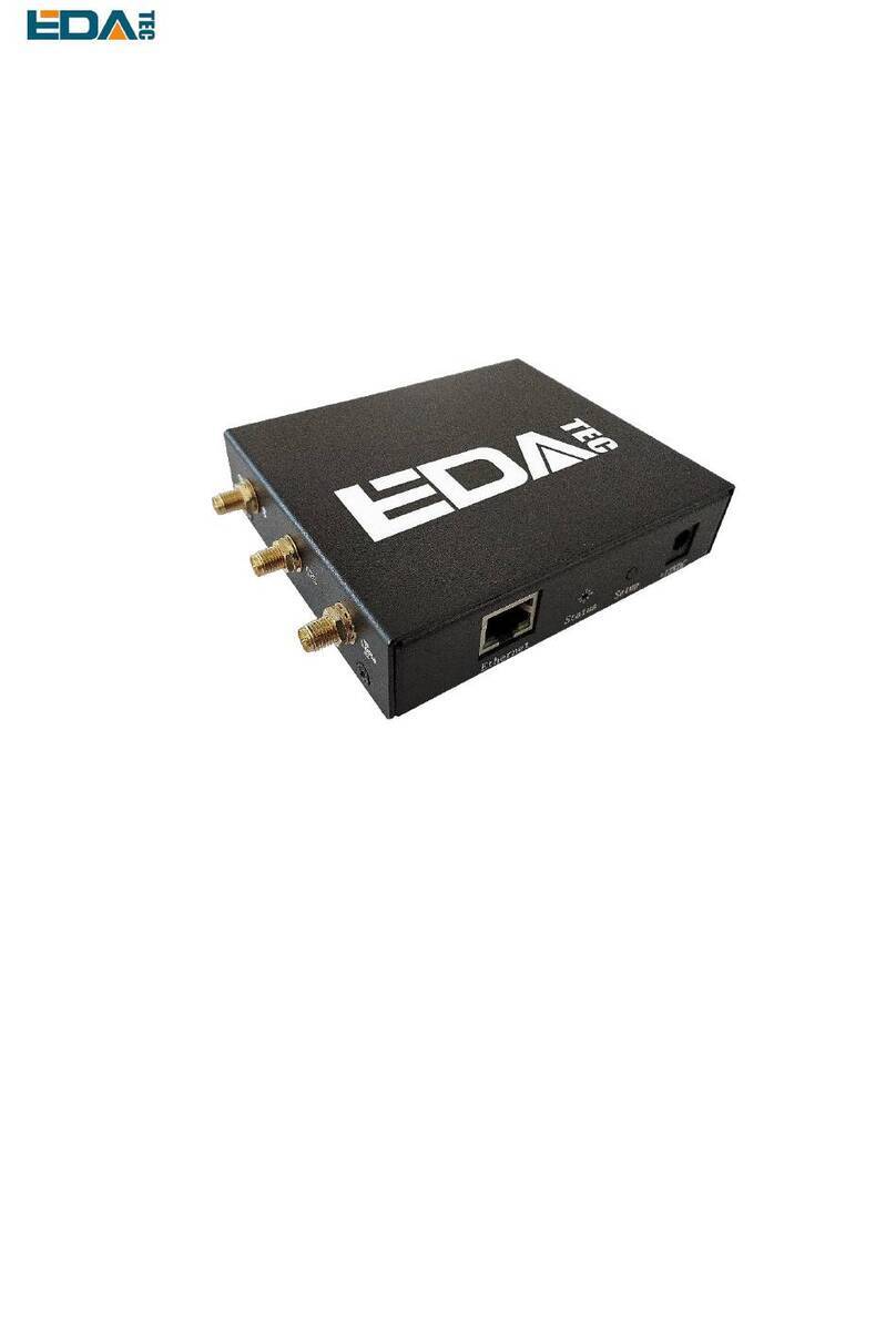
EDA ED-GWL1010 User manual

User Manual of ED-GWL1010
EDATechnology Co.,LTD–Electronics Development Accelerator
ED-GWL1010
A COST-EFFECTIVE LORAWAN INDOOR GATEWAY
Shanghai EDA Technology Co.,Ltd
2023-03-23

User Manual of ED-GWL1010
EDATechnology Co.,LTD–Electronics Development Accelerator
Copyright Statement
ED-GWL1010 and its related intellectual property rights are owned by Shanghai EDATechnology Co., Ltd.
Shanghai EDA Technology Co., Ltd owns the copyright of this document and reserves all rights. Without
the written permission of Shanghai EDA Technology Co., Ltd, no part of this document may be modified,
distributed or copied in any way or form.
Disclaimers
Shanghai EDA Technology Co., Ltd does not guarantee that the information in this manual is up to date,
correct, complete or of high quality. Shanghai EDATechnologyCo., Ltd also does not guarantee the further
use of this information. If the material or non-material related losses are caused by using or not using the
information in this manual, or by using incorrect or incomplete information, as long as it is not proved that
it is the intention or negligence of Shanghai EDATechnology Co., Ltd, the liability claim for Shanghai EDA
Technology Co., Ltd can be exempted. Shanghai EDATechnology Co., Ltd expressly reserves the right to
modify or supplement the contents or part of this manual without special notice.

User Manual of ED-GWL1010
EDATechnology Co.,LTD–Electronics Development Accelerator
Contents
1Product Overview..................................................................................................................................5
1.1 TargetApplication....................................................................................................................... 5
1.2 Specifications and Parameters..................................................................................................5
1.3 System Diagram......................................................................................................................... 6
1.4 Functional Layout....................................................................................................................... 6
1.5 Packing List................................................................................................................................ 8
1.6 Order Code ................................................................................................................................8
2Quick Start ............................................................................................................................................ 8
2.1 Equipment List ...........................................................................................................................8
2.2 Hardware Connection................................................................................................................9
2.3 First Start.................................................................................................................................... 9
2.3.1 Use SSH.......................................................................................................................... 9
2.3.2 SSH Tool .........................................................................................................................9
2.3.3 Get The Device IP...........................................................................................................9
2.3.4 SSH remote login..........................................................................................................10
3Wiring Guide ....................................................................................................................................... 10
3.1 Internal I/O ...............................................................................................................................10
3.1.1 micro-SD Card ..............................................................................................................10
3.1.2 TTL Serial Port...............................................................................................................11
4Software Operation Guide ...................................................................................................................11
4.1 Button........................................................................................................................................11
4.1.1 Install libgpiod ................................................................................................................11
4.1.2 Button Test .................................................................................................................... 14
4.2 LED Indication.......................................................................................................................... 14
4.3 USB..........................................................................................................................................15
4.3.1 Check USB device information.....................................................................................15
4.3.2 USB Storage Device Mounting..................................................................................... 16
4.4 Ethernet Configuration............................................................................................................. 17
4.5 WiFi..........................................................................................................................................18
4.6 Bluetooth.................................................................................................................................. 18
4.7 Serial Communication.............................................................................................................. 19
4.7.1 Install picocom Tool.......................................................................................................19
4.7.2 Debug UART.................................................................................................................20
4.8 LoRaWAN ................................................................................................................................20
4.8.1 Install LoRa Service and ChirpStack Client..................................................................20
4.8.2 Configuring LoRa Service.............................................................................................21
4.8.3 Install ChirpStack Server ..............................................................................................23
4.8.4 Adding LoRa Gateway and Terminal ............................................................................25
5Operating System Installation.............................................................................................................28
5.1 Image Download...................................................................................................................... 28
5.2 System Flash ........................................................................................................................... 29
5.2.1 Flash from SD card....................................................................................................... 29

User Manual of ED-GWL1010
EDATechnology Co.,LTD–Electronics Development Accelerator
5.2.2 eMMC Flash..................................................................................................................29
6FAQ..................................................................................................................................................... 31
6.1.1 Default Username and Password.................................................................................31
7About Us ............................................................................................................................................. 31
7.1 About EDATEC ........................................................................................................................ 31
7.2 Contact Us ............................................................................................................................... 31

User Manual of ED-GWL1010
EDATechnology Co.,LTD–Electronics Development Accelerator
1 Product Overview
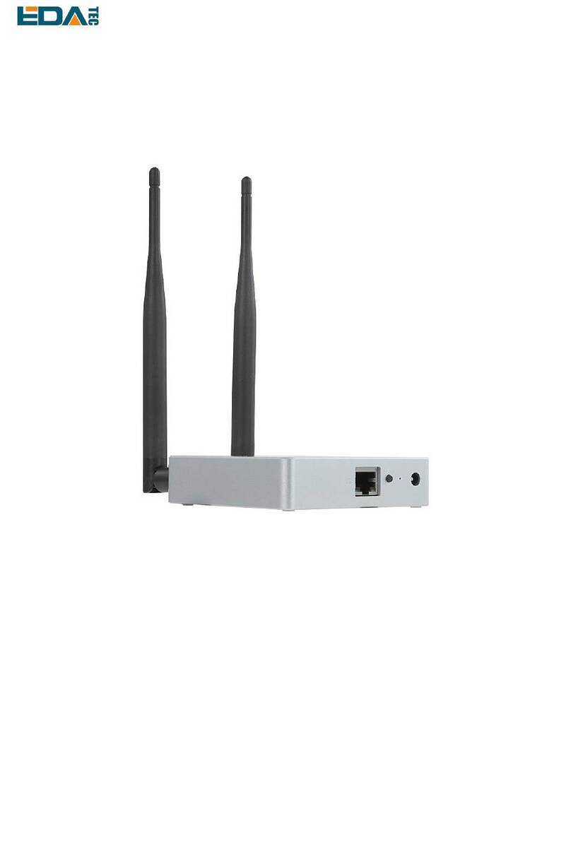
ED-GWL1010 is a cost-effective LoRaWAN indoor gateway product launched by EDATEC. The ED-
GWL1010 is based on EDATEC's brand-new 1(ED-REIMEI1) single-board computer platform, adopting
the form of motherboard and expansion board, integrating Semtech's new generation SX1302/SX103
baseband chip and Microchip security encryption chip ATECC608, supporting DC Jack power supply and
PoE power supply, and optional sheet metal casing.
1.1 Target Application
LoRa intelligent gateway
Industrial control
Smart manufacturing
Smart city
Smart transportation
1.2 Specifications and Parameters
Function
Parameters
CPU
AMLogic S905X4 4 core, ARM Cortex-A55(ARM v8), 2GHz, 64bit CPU
Memory
Option 1GB / 2GB / 4GB / 8GB LPDDR-3200 SDARM
eMMC flash
Option 0GB / 8GB / 16GB / 32GB
SD card
Can be used with eMMC at the same time, and can be started from SD
card
Ethernet
1x 10/100M Ethernet, support PoE
WiFi / Bluetooth
2.4G / 5.8G dual WiFi, bluetooth 5.0
LoRa
LoRa gateway module based on Semtech SX1302+SX1250 has passed
CE/FCC certification and can be selected from European version or
American version
LoRa Frequency
American version: US915, AU915, AS923
European version: EU868
USB Host
1x USB 3.0 Type A, 1x USB 2.0 Type A
mini PCIe
1x mini PCIe Slot, support SPI bus,used to extended LoRa gateway
module
LED Indicator
1x RGB LED
Button
1x User Button

User Manual of ED-GWL1010
EDATechnology Co.,LTD–Electronics Development Accelerator
Function
Parameters
Power Input
7V ~ 18V
Dimensions
110 (L) x 90 (W) x 26 mm (H)
case
Desktop type, sheet metal shell
Antenna accessory
1x WiFi / BT External antenna, 1x LoRa External antenna
Working
environment temperature
-25 ~ 50°C
OS
Debian 11, Lite, 64-bit OS
Software resources
Provide example guidance for LoRaWAN networks such as ChipStack
1.3 System Diagram
1.4 Functional Layout

User Manual of ED-GWL1010
EDATechnology Co.,LTD–Electronics Development Accelerator
Item
Function Description
Item
Function Description
A1
12V DC power socket
A6
Ethernet RJ45 port
A2
Key
A7
HDMI type A port
A3
RGB LED
A8
Micro USB Power supply port
A4
USB 2.0 port
A9
LoRa mini-PCIe port
A5
USB 3.0 port
Item
Function Description
B1
Debug serial port
B2
Micro SD card slot

User Manual of ED-GWL1010
EDATechnology Co.,LTD–Electronics Development Accelerator
1.5 Packing List
1x ED-GWL1010 host
[option]1x LoRa antenna
[option]1x 2.4GHz/5GHz WiFi/BT antenna
1.6 Order Code
2 Quick Start
2.1 Equipment List
1x ED-GWL1010 host
1x WiFi / BT external antenna
1x LoRa external antenna
1x net cable
1x 12V@2A power supply

User Manual of ED-GWL1010
EDATechnology Co.,LTD–Electronics Development Accelerator
2.2 Hardware Connection
1. Install the WiFi external antenna.
2. Install LoRa external antenna.
3. Insert the network cable into the Ethernet port, and the network cable is connected with network
devices such as routers and switches that can access the Internet.
4.Plug in the DC power input port (+12V DC) of ED-GWL1010 and supply power to the power adapter.
2.3 First Start
ED-GWL1010 has no power switch. Plug in the power cord and the system will start to start.
2.3.1 Use SSH
Enable SSH automatically at startup:
When the device is started, an empty file named ssh is put into the boot partition before booting, and
SSH will be automatically enabled after booting.
Command enables SSH:
sudo raspi-config
After entering the above command, a command line interface will appear. Configure the third interface.
Find SSH and select yes to enable SSH function.
3 Interface Options -> 2 SSH -> Yes
2.3.2 SSH Tool
Windows recommends using putty to realize SSH remote connection.
- Putty Download:Download PuTTY - a free SSH and telnet client for Windows
2.3.3 Get The Device IP
If the display screen is connected, you can use the ifconfig command to find the current device IP.
If there is no display screen, you can view the assigned IP through the router.
If there is no display screen, you can download the nmap tool to scan the IP under the current
network.
Nmap supports Linux, macOS, Windows and other platforms. If you want to use nmap to scan the
network segments from 192.168.3.0 to 255, you can use the following command:
nmap -sn 192.168.3.0/24
After waiting for a period of time, the result will be output:
Starting Nmap 7.92 ( https://nmap.org ) at 2022-12-30 21:19 中国标准时间
Nmap scan report for 192.168.3.1 (192.168.3.1)

User Manual of ED-GWL1010
EDATechnology Co.,LTD–Electronics Development Accelerator
Host is up (0.0010s latency).
MAC Address: XX:XX:XX:XX:XX:XX (Phicomm (Shanghai))
Nmap scan report for DESKTOP-FGEOUUK.lan (192.168.3.33)
Host is up (0.0029s latency).
MAC Address: XX:XX:XX:XX:XX:XX (Dell)
Nmap scan report for 192.168.3.66 (192.168.3.66)
Host is up.
Nmap done: 256 IP addresses (3 hosts up) scanned in 11.36 seconds
2.3.4 SSH remote login
ssh phantom@<IP>
User name:phantom
Password :phantom
Port:22
3 Wiring Guide
3.1 Internal I/O
3.1.1 micro-SD Card
The micro SD card slot is located on the back of the motherboard. Please insert the micro SD card slot
with the front side facing up in parallel.

User Manual of ED-GWL1010
EDATechnology Co.,LTD–Electronics Development Accelerator
3.1.2 TTL Serial Port
The TTL serial port is located on the back of the LoRa interface board. Please connect the serial port as
shown in the figure below.
4 Software Operation Guide
4.1 Button
The ED-GWL1010 has a user button, and the user can customize the button function. The button is
connected with PIN16, which is high by default, and when the key is pressed, the pin is low.
We use libgpiod library and command line tools to set and read GPIO.
4.1.1 Install libgpiod
Install ligpiod
sudo apt-get update
#Install the static library and header file of libgpiod.
sudo apt-get install libgpiod-dev
#Install command-line tools based on libgpiod
sudo apt-get install gpiod

User Manual of ED-GWL1010
EDATechnology Co.,LTD–Electronics Development Accelerator
libgpiod supports six command-line test commands:
gpiodetect - List all gpiochips existing on the system, their names, labels and number of GPIO lines.
gpioinfo - Lists all lines of the specified gpiochips, their names, consumers, directions, activity status
and additional flags.
gpioget - Read the value of the specified GPIO line.
gpioset - Sets the value of the specified GPIO lines, which may be kept for export and waiting for
timeout, user input or signal.
gpiofind - Find the row offset of the gpiochip name and the given row name.
gpiomon - Wait for the event on the GPIO line, specify the event to watch, how many events to
handle before exiting or how many events should be reported to the console.
Use GPIOinfo command to view gpio information.
phantom@phantom:~ $ gpioinfo
gpiochip0 - 87 lines:
line 0: "PIN27" kernel input active-high [used]
line 1: "PIN28" kernel input active-high [used]
line 2: "EMMC_DAT0" kernel input active-high [used]
line 3: "EMMC_DAT1" kernel input active-high [used]
line 4: "EMMC_DAT2" kernel input active-high [used]
line 5: "EMMC_DAT3" kernel input active-high [used]
line 6: "EMMC_DAT4" kernel input active-high [used]
line 7: "EMMC_DAT5" kernel input active-high [used]
line 8: "EMMC_DAT6" kernel input active-high [used]
line 9: "EMMC_DAT7" kernel input active-high [used]
line 10: "EMMC_CLK" kernel input active-high [used]
line 11: "NAND_ALE" unused input active-high
line 12: "EMMC_CMD" kernel input active-high [used]
line 13: "-" unused input active-high
line 14: "EMMC_RST" unused input active-high
line 15: "EMMC_NAND_DQS" kernel input active-high [used]
line 16: "-" unused input active-high
line 17: "-" unused input active-high
line 18: "SD_DAT0" kernel input active-high [used]
line 19: "SD_DAT1" kernel input active-high [used]
line 20: "SD_DAT2" kernel input active-high [used]
line 21: "SD_DAT3" kernel input active-high [used]
line 22: "SD_CLK" kernel input active-high [used]
line 23: "SD_CMD" kernel input active-high [used]
line 24: "SD_CD" "cd" input active-high [used]
line 25: "USB_PSU" "fe03a080.usb3phy" output active-low [used]
line 26: "VDDEE_PWM" unused input active-high
line 27: "VDDCPU_PWM" kernel input active-high [used]
line 28: "LED" "act" output active-high [used]
line 29: "DEBUG_TX" kernel input active-high [used]

User Manual of ED-GWL1010
EDATechnology Co.,LTD–Electronics Development Accelerator
line 30: "DEBUG_RX" kernel input active-high [used]
line 31: "PIN40" unused input active-high
line 32: "PIN31" unused input active-high
line 33: "PIN12" unused input active-high
line 34: "-" unused input active-high
line 35: "PIN32" unused input active-high
line 36: "PIN29" unused input active-high
line 37: "PIN8" kernel input active-high [used]
line 38: "PIN10" kernel input active-high [used]
line 39: "-" unused input active-high
line 40: "PIN35" unused input active-high
line 41: "HDMI_SDA" kernel input active-high [used]
line 42: "HDMI_SCL" kernel input active-high [used]
line 43: "HDMI_HPD" kernel input active-high [used]
line 44: "HDMI_CEC" kernel input active-high [used]
line 45: "PIN19" kernel input active-high [used]
line 46: "PIN21" kernel input active-high [used]
line 47: "PIN24" "spi0.0" output active-high [used]
line 48: "PIN23" kernel input active-high [used]
line 49: "PCIE_RESET" unused input active-high
line 50: "WIFI_SD_D0" kernel input active-high [used]
line 51: "WIFI_SD_D1" kernel input active-high [used]
line 52: "WIFI_SD_D2" kernel input active-high [used]
line 53: "WIFI_SD_D3" kernel input active-high [used]
line 54: "WIFI_SD_CLK" kernel input active-high [used]
line 55: "WIFI_SD_CMD" kernel input active-high [used]
line 56: "-" unused input active-high
line 57: "-" unused input active-high
line 58: "-" unused input active-high
line 59: "-" unused input active-high
line 60: "BT_ON" "shutdown" output active-high [used]
line 61: "WL_ON" unused input active-high
line 62: "BTUART_A_TX" kernel input active-high [used]
line 63: "BTUART_A_RX" kernel input active-high [used]
line 64: "BTUART_A_CTS_N" kernel input active-high [used]
line 65: "BTUART_A_RTS_N" kernel input active-high [used]
line 66: "-" unused input active-high
line 67: "-" unused input active-high
line 68: "-" unused input active-high
line 69: "-" unused input active-high
line 70: "PIN3" kernel input active-high [used]
line 71: "PIN5" kernel input active-high [used]
line 72: "PIN18" unused input active-high
line 73: "PIN22" unused input active-high

User Manual of ED-GWL1010
EDATechnology Co.,LTD–Electronics Development Accelerator
line 74: "PIN37" unused input active-high
line 75: "PIN13" unused input active-high
line 76: "PIN15" unused input active-high
line 77: "PIN16" unused input active-high
line 78: "PIN26" "spi0.1" output active-high [used]
line 79: "PIN11" unused input active-high
line 80: "PIN36" unused input active-high
line 81: "PIN38" unused input active-high
line 82: "PIN33" unused input active-high
line 83: "PIN7" unused input active-high
line 84: "LAN_LEDG" kernel input active-high [used]
line 85: "LAN_LEDY" kernel input active-high [used]
line 86: "-" unused input active-high
It can be seen that the system has only one gpiochip0 with 87 GPIO pins, and the GPIO that has been
driven or occupied by the system will be displayed as [used] in the last column.
4.1.2 Button Test
According to the name of the GPIO pin in the data sheet ED-GWL1010_Datasheet_CN.pdf and the return
result of gpioinfo, the corresponding line number is found. The pin name corresponding to GPIO23 is
PIN16, and the line number corresponding to PIN16 is 77.
phantom@phantom:~ $ gpioinfo | grep PIN16
line 77: "PIN16" unused input active-high
Configure GPIO input
#Read chip0 line77 Pin state
gpioget 0 77
When the return value is 1, it means that the pin of line77 or PIN16 is high, and when the return value is
0, it means that the pin of line77 or PIN16 is low.
4.2 LED Indication
The RGB LED of ED-GWL1010 is controlled by three GPIO. The control pins are GPIO16 to control blue,
GPIO20 to control green, GPIO21 to control red, and GPIO is active at low level.
According to the GPIO pin name in the data sheet ED-GWL1010_Datasheet_CN.pdf and the return
result of gpioinfo, the corresponding line number is found.
The pin name of GPIO16 is PIN36, and the line number of PIN36 is 80.
The pin name of GPIO20 is PIN38, and the line number of PIN38 is 81.
The pin name of GPIO21 is PIN40, and the line number of PIN40 is 31.

User Manual of ED-GWL1010
EDATechnology Co.,LTD–Electronics Development Accelerator
Configure the blue light on.
#Set the line80 pin of chip0 to low level.
gpioset 0 80=0
Configure the blue light off.
#Set the line80 pin of chip0 to high level.
gpioset 0 80=1
Configure the green light on.
#Set the line81 pin of chip0 to low level.
gpioset 0 81=0
Configure the green light off.
#Set the line81 pin of chip0 to high level.
gpioset 0 81=1
Configure the red light on.
#Set the line31 pin of chip0 to low level.
gpioset 0 31=0
Configure the red light off.
#Set the line31 pin of chip0 to high level.
gpioset 0 31=1
4.3 USB
ED-GWL1010 具有一个 USB2.0 A 型接口和一个 USB3.0 A 型接口。ED-GWL1010 has a USB2.0Aport
and a USB3.0 A port.
4.3.1 Check USB device information
List USB Device
lsusb
The information displayed is as follows:
Bus 002 Device 001: ID 1d6b:0003 Linux Foundation 3.0 root hub
Bus 001 Device 005: ID 1a2c:2d23 China Resource Semico Co., Ltd Keyboard
Bus 001 Device 004: ID 30fa:0300 USB OPTICAL MOUSE
Bus 001 Device 003: ID 0424:9e00 Microchip Technology, Inc. (formerly SMSC)
LAN9500A/LAN9500Ai
Bus 001 Device 002: ID 1a40:0201 Terminus Technology Inc. FE 2.1 7-port Hub
Bus 001 Device 001: ID 1d6b:0002 Linux Foundation 2.0 root hub

User Manual of ED-GWL1010
EDATechnology Co.,LTD–Electronics Development Accelerator
4.3.2 USB Storage Device Mounting
You can connect an external hard disk, SSD or USB stick to any USB port on Raspberry Pi and mount
the file system to access the data stored on it.
In general, you can directly use the following commands to mount or unmount external storage devices.
lsblk
NAME MAJ:MIN RM SIZE RO TYPE MOUNTPOINT
sda 8:0 1 29.1G 0 disk
└─sda1 8:1 1 29.1G 0 part
mmcblk0 179:0 0 59.5G 0 disk
├─mmcblk0p1 179:1 0 256M 0 part /boot
└─mmcblk0p2 179:2 0 59.2G 0 part /
Use the mount command to mount sda1 to the /mnt directory.After the mount is completed, users can
directly operate storage devices in the /mnt directory.
sudo mount /dev/sda1 /mnt
After using, use the command umount to uninstall the storage device.
sudo umount /mnt
4.3.2.1 Mount
You can install the storage device in a specific folder location. It is usually done in the /mnt folder, such
as /mnt/mydisk. Please note that the folder must be empty.
1. Insert the storage device into the USB port on the device.
2. Use the following command to list all disk partitions on the system:
sudo lsblk -o UUID,NAME,FSTYPE,SIZE,MOUNTPOINT,LABEL,MODEL
The file system uses mount points/and /boot. Your storage device will appear in this list, along with
any other connected storage devices.
3. Use the Size, Label and Model columns to identify the name of the disk partition that points to your
storage device. For example, sda1,mmcblk0.
4. The FSTYPE column contains file system types. If your storage device uses the exFAT file system,
please install the exFAT driver:
sudo apt update
sudo apt install exfat-fuse
5. If your storage device uses NTFS file system, you will have read-only access to it. If you want to
write to the device, you can install the ntfs-3g driver:
sudo apt update
sudo apt install ntfs-3g

User Manual of ED-GWL1010
EDATechnology Co.,LTD–Electronics Development Accelerator
6. Run the following command to get the location of the disk partition:
sudo blkid
like, /dev/sda1
7. Create a target folder as the mount point of the storage device. The mount point name used in this
example is mydisk. You can specify a name of your choice:
sudo mkdir /mnt/mydisk
8. Mount the storage device at the mount point you created:
sudo mount /dev/sda1 /mnt/mydisk
9. Verify that the storage device has been successfully mounted by listing the following:
ls /mnt/mydisk
4.3.2.2 Unmount
When the device is turned off, the system will unmount the storage device so that it can be pulled out
safely. If you want to uninstall the device manually, you can use the following command:
sudo umount /mnt/mydisk
If you receive a "destination busy" error, it means that the storage device has not been unmounted. If no
error is displayed, you can safely unplug the device now.
4.3.2.3 Set Up Automatic Mount In The Command Line
You can modify the fstab setting to mount automatically.
1. First, you need to get the disk UUID.
sudo blkid
2. Find the UUID of the mounted device, such as 5C24-1453.
3. Open the fstab file
sudo nano /etc/fstab
4. Add the following to the fstab file
UUID=5C24-1453 /mnt/mydisk fstype defaults,auto,users,rw,nofail 0 0
Replace fstype with the type of your file system, which you can find in step 2 of "Mounting storage
devices" above, for example, ntfs.
5. If the file system type is FAT or NTFS, adding umask = 000 immediately after nofail will allow all
users full read/write access to every file on the storage device.
Can use man fstab to learn more information about fstab.
4.4 Ethernet Configuration
The system uses dhcpcd for network management by default.
Configure static IP, set the static IP of eth0 network card to 192.168.168.108, set the default route to
192.168.168.1, and set DNS to 192.168.168.1(DNS can be omitted):

User Manual of ED-GWL1010
EDATechnology Co.,LTD–Electronics Development Accelerator
sudo nano /etc/dhcpcd.conf
interface eth0
static ip_address=192.168.168.108/24
static route=192.168.168.1
static domain_name_servers=192.168.168.1
4.5 WiFi
4.5.1.1 Scans Available WiFi Networks.
sudo iwlist wlan0 scan
4.5.1.2 Connect to WiFi
Method 1:
sudo raspi-config
Select 1 System Options to find S1 Wireless LAN. For the first time, you need to select a country, and
China is CN. Then you will be asked to enter the WiFi name, then enter the WiFi password, and then
save and exit. If the country code is set, it needs to be restarted.
Method 2:
sudo nano /etc/wpa_supplicant/wpa_supplicant.conf
Add the following to the file
country=CN
network={
ssid="WiFi_SSID"
psk="Password"
}
Ctrl+X exits and returns to save.
4.6 Bluetooth
Bluetooth function is enabled by default. If you need to set Bluetooth, you can use the bluetoothctl
command to set Bluetooth.
Scan
bluetoothctl scan on/off
Find device
bluetoothctl discoverable on/off

User Manual of ED-GWL1010
EDATechnology Co.,LTD–Electronics Development Accelerator
Truct device
bluetoothctl trust [MAC]
Pair
bluetoothctl pair [MAC]
Connect
bluetoothctl connect [MAC]
Disconnect
bluetoothctl disconnect [MAC]
More buletooth configuration command
bluetoothctl
help
4.7 Serial Communication
ED-GWL1010 has a TTL level serial port, and the interface name is J4, which is used as the debugging
serial port by default.
4.7.1 Install picocom Tool
Picocom serial terminal can be debugged conveniently in Linux environment.
First install picocom
sudo apt-get install picocom
After opening the corresponding serial port with picocom, you can type Ctrl+a and then Ctrl+h to see the
available commands.
*** Picocom commands (all prefixed by [C-a])
*** [C-x] : Exit picocom
*** [C-q] : Exit without reseting serial port
*** [C-b] : Set baudrate
*** [C-u] : Increase baudrate (baud-up)
*** [C-d] : Decrease baudrate (baud-down)
*** [C-i] : Change number of databits
*** [C-j] : Change number of stopbits
*** [C-f] : Change flow-control mode
*** [C-y] : Change parity mode
*** [C-p] : Pulse DTR
*** [C-t] : Toggle DTR

User Manual of ED-GWL1010
EDATechnology Co.,LTD–Electronics Development Accelerator
*** [C-g] : Toggle RTS
*** [C-|] : Send break
*** [C-c] : Toggle local echo
*** [C-w] : Write hex
*** [C-s] : Send file
*** [C-r] : Receive file
*** [C-v] : Show port settings
*** [C-h] : Show this message
Type Ctrl+a first, then Ctrl+c to switch the local echo mode.
Type Ctrl+a first, then Ctrl+q to exit picocom.
4.7.2 Debug UART
To enable debugging serial port, you need to modify the config.txt configuration file.
sudo nano /boot/config.txt
Add at the end
[all]
enable_uart=1
The default baud rate of debugging serial port is 115200. You can check the current baud rate of
debugging serial port through cmdline.txt file.
sudo nano /boot/cmdline.tx
4.8 LoRaWAN
ED-GWL1010 supports LoRaWAN open source service platform ChipStack. Please refer to the following
steps for installation and configuration.
4.8.1 Install LoRa Service and ChirpStack Client.
We install it byAPT.
Add edatec APT warehouse
$ curl -sS https://apt.edatec.cn/pubkey.gpg | sudo apt-key add -
$ echo "deb https://apt.edatec.cn/raspbian stable main" | sudo tee /etc/apt/sources.list.d/edatec.list
$ sudo apt update
$ sudo apt install -y ed-gwl-pktfwd
Install ChirpStack
Table of contents
Other EDA Gateway manuals
Popular Gateway manuals by other brands
Electro Industries/GaugeTech
Electro Industries/GaugeTech ProtoCom Installation & operation manual
STRIDE
STRIDE MQTT manual

Memco
Memco 452 003 installation guide
DEUTSCHMANN AUTOMATION
DEUTSCHMANN AUTOMATION UNIGATE CX-CANopen - DeviceNet manual
TRBOnet
TRBOnet Swift A200 user manual
Cisco
Cisco TES301 Quick reference guide
